US3797669A - Device for displaying carpet samples - Google Patents
Device for displaying carpet samples Download PDFInfo
- Publication number
- US3797669A US3797669A US00246331A US3797669DA US3797669A US 3797669 A US3797669 A US 3797669A US 00246331 A US00246331 A US 00246331A US 3797669D A US3797669D A US 3797669DA US 3797669 A US3797669 A US 3797669A
- Authority
- US
- United States
- Prior art keywords
- holders
- pair
- structure according
- holding means
- ear
- Prior art date
- Legal status (The legal status is an assumption and is not a legal conclusion. Google has not performed a legal analysis and makes no representation as to the accuracy of the status listed.)
- Expired - Lifetime
Links
Images


Classifications
-
- A—HUMAN NECESSITIES
- A47—FURNITURE; DOMESTIC ARTICLES OR APPLIANCES; COFFEE MILLS; SPICE MILLS; SUCTION CLEANERS IN GENERAL
- A47F—SPECIAL FURNITURE, FITTINGS, OR ACCESSORIES FOR SHOPS, STOREHOUSES, BARS, RESTAURANTS OR THE LIKE; PAYING COUNTERS
- A47F7/00—Show stands, hangers, or shelves, adapted for particular articles or materials
- A47F7/16—Show stands, hangers, or shelves, adapted for particular articles or materials for carpets; for wallpaper; for textile materials
- A47F7/17—Show stands, hangers, or shelves, adapted for particular articles or materials for carpets; for wallpaper; for textile materials in rolls or rolled tapes
Definitions
- ABSTRACT 58 Field of Search 211/44, 45, 71, 74, 72, T1115 Invention relates to a holder adapted to be 31/177, 2 2 533 &7; 20 72; mounted in a framework and to receive a carpet sam- 248/314, 3 3464 ple in the form of a roll comprising a base portion, wall means at the edge of said base portion and ex- [56] References Cited I tending substantially normal to the plane of said base UNITED STATES PATENTS portion, and means on said holder whereby it may be J mounted in a framework.
- the present invention relates'to a device designed for carpet samples which are rolled up in a roll, wherein each roll is enclosed by a holder at each end face thereof, and wherein the holders are kept at a distance with respect to each other by means of connecting elements.
- the carpet samples are suspended on brackets which are similar to clothes hangers, and these brackets or hangers are hooked into a rod.
- This device or arrangement is suitable, however, only for relatively small carpet samples, whereas the customers really wish to see as large a sample as possiblein order to better be able to evaluate it.
- the heretofore proposed devices for displaying carpet samples have the further disadvantage that theyhardly can be aesthetically advantageously arranged in a display. room. In contrast thereto, they actually look inorganic in a display room and take up much space because of the bulky configuration thereof.
- each holder or holding means has a bottom from the edge of which project holding or supporting members essentially at a right angle to the plane of extension thereof, at least on one side of this plane.
- a carpet sample In order to be introduced into the device of the present invention, a carpet sample must be first rolled up and then inserted between the two holders being provided at a distance from each other. When the carpet sample'is then released, it will unroll again to some extent due to its proper elasticity until it is seized or grasped by the two holders or holding means within the area of the end faces thereof. No additional clamping or fastening means of any kind are required for holding the carpet sample in this case.
- the carpet sample By virtue of the fact that the. carpet sample is loosely wound or rolled up by the inventive device, the carpet sample also.is not bent or cracked. When the carpet sample is taken out of the device in order to be displayed and shown to a customer in the entire length thereof, it may be smoothly stretched out flat on the floor.
- the inventive device further has the advantage that-even larger samples may be accommodated within a relatively small amount of space. For example, a sample having a size of 70 centimeters by ISO centimeters may be rolled up to form a roll which is 70 centimeters high and has a diameter of centimeters.
- Each holder or holding means on one side of the plane of the bottom thereof is advantageously provided only for receiving the end face of one roller.
- the holders or holding means and the connecting elements or pieces thereof may be put together to form display walls of almost any desired size and of almost any desired configuration.
- the holding members project from both sides of the plane of the bottom.
- This construction or provision renders it possible to make up an entire column of rolled-up carpet samples by virtue of the fact that the carpet samples are disposed in alignment with the roller axes thereof.
- one holder or holding means serves in each case for simultaneously holding in place those end faces of carpet samples which are adjacent in the roller axis direction. In this manner it is possible to arrange several rolled-up carpet samples either vertically above each other, or horizontally next to each other.
- the holding members may vbe formed by a wall surrounding the edge of the bottom. This affords the advantage that the end face of a rolled-up carpet sample is completely enclosed outwardly, and as a consequence thereof, the carpet edge or border which sometimes becomes unsightly to view or look at because of fraying is conveniently covered. In contrast thereto, the continuous wall conveys a quiet, aesthetically pleasing impression.
- the wall in the case of one holder will project farther from the floor thereof than is the case for the other holder. If, for example, a carpet sample is intended to be vertically positioned with the roller axis thereof, the holder whose wall projects farther from the bottom thereof will be disposed at the upper side of the carpet sample, while the other holder or holding means will be disposed below.
- the rolled-up carpet sample is first of all inserted far into the upper holder; it is thereafter brought into alignment with the lower holder and lastly lowered thereinto.
- the holders or holding means are suitably so provided and arranged that the wall thereof on both sides of the plane of extension of the bottom'will project to a varying degree from theedge of the bottom.
- the holders or holding means of adjacent end faces of carpet samples are in each case combined to form one piece.
- a slot in the wall which extends almost tangentially with respect to this wall and is continued to the bottom, and which further allows for the insertion thereinto of a carpet sample. Since both holding means for a carpet sample have these slots, the carpet sample does need not be first rolled up in order to be introduced into the holders, but may be instead just inserted into the slots, whereby it will be automatically rolled up.
- no holding members need be provided at a larger, continuous marginal area.
- This marginal area must, however, be at least so large that a carpet sample which is tightly rolled up may be slid or inserted into the holder or holding means in this marginal area but, on the other hand, it must only be so large that the carpet sample is securely held in position within the holders by the holding members when it has become unrolled, after being released, by virtue of its own elasticrty.
- the bottom advantageously has an approximately circular configuration.
- the carpet samples will then become rolled up, after having been inserted and released, due to the influence of their own elasticity, so as to essentially form cylinders having a circular crosssection.
- the bottom also may be oval, however. In that case, the carpet samples will become rolled up to form a cylinder having a corresponding cross-section.
- the latter construction or embodiment may be advantageous, for example, when a great many carpet samples are intended to be arranged side-by-side.
- each holder has at the edge thereof two diametrically opposite ear-shaped carrying members which project from the edge approximately at the height of the bottom thereof. On these carrying or supporting members the holders may be suspended.
- the carrying or supporting members of one holder are advantageously arranged offset, with respect to the plane of the bottom thereof in each case at opposite sides of this plane by about halfthe material thickness thereof measured at a right angle to the plane, and one of the carrying or supporting members is provided with a lug portion while the other carrying or supporting member is provided with a recess into which the lug portion fits, and both the lug portion and the recess alike extend at a right angle to the plane of the bottom.
- the individual holders may be connected with each other in an articulated manner.
- Each carrying or supporting member is advantageously provided with a guiding projection for a rodshaped carrier which projects from it essentially at a right angle to the plane of the bottom, preferably a cylindrical tube, by means of which carrier the holders are carried or supported.
- a guiding projection for a rodshaped carrier which projects from it essentially at a right angle to the plane of the bottom, preferably a cylindrical tube, by means of which carrier the holders are carried or supported.
- a frame similar to the one described hereinabove also may be made up, or constructed, if -in the case of the holders which extend almost tangentially to the wall thereof and reach the bottom while comprising a slot allowing for the insertion of a carpet sample there is disposed, in the center of the bottom thereof, at least on one side, a guide element for a rod-shaped carrier, projecting vertically from the floor. If the stability of such a frame or framework should not be sufficient, it is possible to provide at the holders additional devices or means with the aid of which they may be fastened, for example, to a wall.
- the holders expediently may consist of plastic and can be made, for example, according to the injection molding process.
- the holders may be rigidly cemented to the carrier at the carrying or supporting members.
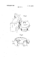
- FIG. 1 illustrates a frame of plate-shaped holders and tubes, such as is proposed by the present invention
- FIG. 2 is a schematic top plan view of a plate-shaped holder, such as is proposed by the present invention, as it is used for the frame according to FIG. 1;
- FIG. 3 is a vertical cross-section taken along line III- -III at point A in FIG. 1, and the position of the crosssectional line is apparent from FIG. 2;
- FIG. 4 is a detailed perspective view of the carrying or supporting member of a plate-shaped holder according to the present invention.
- FIG. 5 is a perspective view of a further embodiment of a plate-shaped holder according to the present invention.
- FIG. 6 is a perspective view of a further embodiment of a holder according to the present invention.
- FIG. 7 is a cross-sectional view of the holder shown in FIG. 6.
- the frame or framework shown in FIG. 1 comprises a holder 1, carrying or supporting tubes 2, and various tubular spacer means 3.
- Each holder 1 has a planar bottom 4 which, at the edge thereof, is enclosed or surrounded by a wall 5 and provided integral therewith.
- the bottom 4 is circular, and the wall 5 forms a cylinder.
- the bottom 4 is disposed closer to one end face of the cylinder constituted or formed by the wall 5.
- These ear-shaped carrying or supporting members 6 and 7 whose configuration is apparent from FIG. 2, are mounted in each case at a different height of the cylinder formed by the wall 5. It is thus possible to dispose adjacent holders 1 in overlapping carrying or supporting members 6 and/or 7 at the same height or level, and side-by-side.
- the holders 1 are carried or supported by the carrying or supporting tubes 2 and kept at a distance with respect to each other.
- tubular separator or distance members or pieces are disposed at those points or places of the supporting or carrying members where no carrying or supporting tubes 2 are necessary, such as approximately below the carrying members at the far left and/or at the far right in FIG. 1
- the carrying or supporting tubes 2 may be chosen to be of a uniform length, if the gaps that will then arise in each case at the outer framework portions are compensated for by separator members 3 having a suitable length.
- Illustrated at 12 in phantom in FIG. 1 is a rolled-up carpet sample which is disposed within the framework and held by two holders 1 at the end faces 14 thereof.
- this carpet sample 12 For the purpose of removing this carpet sample 12 from the frame or framework, it is necessary to lift it up until it abuts at the upper end face 14 against the bottom 4 of its upper holder 1. At that time it is necessary that the lower end face of the carpet roll which thus has becomeliftedabove the wall 5 of the lower holder 1 be pivoted from out of the holder 1 thereof and then be pivoted off. Thereafter the sample will 'be free.
- FIG. 3 shows in detail the connection of two holders 1 with each other and with the carrying or supporting tubes 2.
- the holder 1 with the carrying or supporting member 7 includes on the upper side of the carrying or supporting member a lug portion or stud 8 which fits into a corresponding recess 9 of the holder 1 with the carrying member 6. Since the carrying or supporting membersviewed in a top plan view are provided round, an articulatedor hinged connection is rendered possible between two holders by virtue of the provision of the lug portion or stud and the recess in the carrying or supporting members. From the carrying member 7, there projects downwardly a cylindrical tube-like projection 10. This projection or extension constitutes a guide for a carrying or supporting tube 2.
- FIG. 4 illustrates a perspective view of a detailed portion of a carrying or supporting member 7 with the lug portion or stud 8 and the guide projection or extension 10.
- the wall 5 is so provided and arranged within the area or zone of the carrying or supporting member 7 that it will come to intimately rest against the carrying or supporting tube 2 over a greater circumference of the carrying or supporting tube 2 over the height of the wall 5
- the frame may be very easily composed, or put together, by means of holders 1, carrying or supporting tubes 2, and distance or separator pieces or elements 3, such as is quite obvious from the drawing, and it is also possible in this connection to test the most favorable erection of the framework, and the best possible adaptation to any possibly existing unevenness of a wall by virtue of the articulated or hinged connection of the holders with one another.
- the individual parts thereof may be cemented to each other, after which a rigid frame or 5 framework is obtained.
- the holders I, the carrying or supporting tubes 2, and the separator or distance pieces or elements 3 are preferably made from plastic material.
- metallic rods or tubes may be provided for this purpose.
- the lug portions or studs 8 of the carrying or supporting members 7 and the carrying or supporting members 7 themselves must be provided with a .bore which is approximately concentric to the axis of the lug portion or stud 8.
- the lug portion or stud 8 as well as the recess 9 will, for this purpose, be provided with a correspondingly larger diameter.
- a metallic rod or a metallic tube may be slid or inserted through the aligning carrying or supporting members 6 and 7-of holders 1 and the coordinated aligning carrying or supporting tubes 2, and if desired, the distance or separator pieces or elements 3.
- clamping means or devices at the ends of these metallic rods or of this metallic tube it is possible to securely clamp together the carrying or supporting members 6 and 7, the supporting or carrying tubes 2, being disposed therebetween, and, if desired, distance or separator pieces or elements 3.
- the latter may be again connected with each other at the ends thereof by means of metallic bands, whereby the framework is given an even greater stability or rigidity.
- the bottom 4 is enclosed with a wall 5 over only a part of the circumference thereof. In this manner it is possible to insert a carpet sample, being tightly rolled up, easily through the thus produced recess between two holders 1. When the carpet sample is then released, it
- a slot is disposed in the wall 5 of this holder which extends in each case to the bottom 4 of the holder and nearly tangentially with respect to the circumference of the wall 5. It is possible to insert a carpet sample through the slot 15, and the latter will automatically become rolled up within the holder during the process or operation of being inserted.
- FIG. 7 It is apparent from FIG. 7 how the holder shown in FIG. 6 may be connected with carrying or supporting holders 2. Approximately in the center of the bottom 4 of the holder 1, one guiding stud or lug portion 16 each will project in each case upwardly and downwardly. A carrying or supporting tube 2 may be slid upon or inserted on this guiding stud.
- carrying or supporting tubes that are disposed in the center of the holders 1 will not be disturbing since the carpet sample is not introduced or inserted into the holders in the already rolled-up condition thereof, but is instead rolled up only in the course of the insertion thereof through the slot while moving around the carrying or supporting tubes 2.
- a structure for displaying carpet samples in rollform comprising, a pair of holders, each of said holders including a generally flat base portion, holding means attached to said base portion at the circumference of said base portion, extending perpendicular thereto and surrounding one end of a carpet sample in roll form and a pair of ear-like mounting members attached to diametrically opposite sides of said holder and extending therefrom parallel to said base portion; and elongated, rod-shaped supports attached to said ear-like mounting members to space said base portions of said pair of holders apart a distance at least equal to the length of a carpet sample in roll-form.
- a structure according to claim 1 wherein an opening is formed in the holding means perpendicular to the base portion of the holders and having a width sufficient to receive a carpet sample in tightly rolled form, whereby a carpet sample may be inserted into said holding means in tightly rolled form and then released to generally conform to the interior shape of said holding means.
- guide projections are mounted on the ear-like mounting members substantially perpendicular to the base portion of the holder and attach the supports to said earlike mounting members.
- mounting means are pivotal mounting means to permit pivoting of one pair of holders with respect to another pair of said holders on an axis perpendicular to the base portions of said holders.
- a structure according to claim 10 wherein the ear-like mounting members of the pair of holders mounted in side by side relationship are offset from one another in a direction perpendicular to the base portions of said holders a distance equal to about one-half the thickness of the base portions of said holders, whereby said ear-like projections of said pairs of holders are in overlapping contact with one another while said pairs of holders are in the same plane.
- the mounting means includes a projection, substantially perpendicular to the base portions of the holders, formed on the ear-like mounting members of one of the pairs of holders and a recess, substantially perpendicular to said base portions of said holders, formed in the ear-like mounting members of the other of said pairs of holders into which said projections fit.
Landscapes
- Supports Or Holders For Household Use (AREA)
- Treatment Of Fiber Materials (AREA)
- Carpets (AREA)
Applications Claiming Priority (1)
| Application Number | Priority Date | Filing Date | Title |
|---|---|---|---|
| DE2120050A DE2120050C3 (de) | 1971-04-23 | 1971-04-23 | Vorrichtung zum Ausstellen von Teppichmustern |
Publications (1)
| Publication Number | Publication Date |
|---|---|
| US3797669A true US3797669A (en) | 1974-03-19 |
Family
ID=5805767
Family Applications (1)
| Application Number | Title | Priority Date | Filing Date |
|---|---|---|---|
| US00246331A Expired - Lifetime US3797669A (en) | 1971-04-23 | 1972-04-21 | Device for displaying carpet samples |
Country Status (7)
| Country | Link |
|---|---|
| US (1) | US3797669A (enExample) |
| AT (1) | AT318851B (enExample) |
| BE (1) | BE782507A (enExample) |
| CH (1) | CH541950A (enExample) |
| DE (1) | DE2120050C3 (enExample) |
| FR (1) | FR2136660A5 (enExample) |
| IT (1) | IT953322B (enExample) |
Cited By (1)
| Publication number | Priority date | Publication date | Assignee | Title |
|---|---|---|---|---|
| US6103378A (en) * | 1998-11-23 | 2000-08-15 | The Mead Company | Capsules having discrete solvent/color former and diluent capsule encapsulated phases |
Citations (7)
| Publication number | Priority date | Publication date | Assignee | Title |
|---|---|---|---|---|
| US662762A (en) * | 1900-07-25 | 1900-11-27 | Eastman Kodak Co | Clip for holding rolls or spools. |
| US831205A (en) * | 1906-02-14 | 1906-09-18 | Ernest C Skiles | Bottle-support. |
| US1124615A (en) * | 1913-10-23 | 1915-01-12 | Walter S Hawk | Dispensing-cabinet. |
| US1289872A (en) * | 1916-12-18 | 1918-12-31 | John L Mueller | Oil-cloth stand. |
| US2694533A (en) * | 1954-03-16 | 1954-11-16 | Zucker Sam | Adhesive tape dispenser |
| DE1060238B (de) * | 1957-08-01 | 1959-06-25 | Walter Fuss | Zusammensetzbarer Staender zum Zurschaustellen von Waren, insbesondere aus Porzellan |
| US3636893A (en) * | 1969-07-08 | 1972-01-25 | Kubel Gmbh Karl | Free-standing household shelf arrangement |
-
1971
- 1971-04-23 DE DE2120050A patent/DE2120050C3/de not_active Expired
-
1972
- 1972-04-19 CH CH576972A patent/CH541950A/de not_active IP Right Cessation
- 1972-04-20 IT IT7276/72A patent/IT953322B/it active
- 1972-04-21 AT AT353872A patent/AT318851B/de not_active IP Right Cessation
- 1972-04-21 US US00246331A patent/US3797669A/en not_active Expired - Lifetime
- 1972-04-21 BE BE782507A patent/BE782507A/xx unknown
- 1972-04-24 FR FR7214507A patent/FR2136660A5/fr not_active Expired
Patent Citations (7)
| Publication number | Priority date | Publication date | Assignee | Title |
|---|---|---|---|---|
| US662762A (en) * | 1900-07-25 | 1900-11-27 | Eastman Kodak Co | Clip for holding rolls or spools. |
| US831205A (en) * | 1906-02-14 | 1906-09-18 | Ernest C Skiles | Bottle-support. |
| US1124615A (en) * | 1913-10-23 | 1915-01-12 | Walter S Hawk | Dispensing-cabinet. |
| US1289872A (en) * | 1916-12-18 | 1918-12-31 | John L Mueller | Oil-cloth stand. |
| US2694533A (en) * | 1954-03-16 | 1954-11-16 | Zucker Sam | Adhesive tape dispenser |
| DE1060238B (de) * | 1957-08-01 | 1959-06-25 | Walter Fuss | Zusammensetzbarer Staender zum Zurschaustellen von Waren, insbesondere aus Porzellan |
| US3636893A (en) * | 1969-07-08 | 1972-01-25 | Kubel Gmbh Karl | Free-standing household shelf arrangement |
Cited By (1)
| Publication number | Priority date | Publication date | Assignee | Title |
|---|---|---|---|---|
| US6103378A (en) * | 1998-11-23 | 2000-08-15 | The Mead Company | Capsules having discrete solvent/color former and diluent capsule encapsulated phases |
Also Published As
| Publication number | Publication date |
|---|---|
| BE782507A (fr) | 1972-08-16 |
| AT318851B (de) | 1974-11-25 |
| DE2120050A1 (de) | 1972-11-02 |
| IT953322B (it) | 1973-08-10 |
| CH541950A (de) | 1973-09-30 |
| DE2120050C3 (de) | 1974-09-26 |
| DE2120050B2 (de) | 1974-03-07 |
| FR2136660A5 (enExample) | 1972-12-22 |
Similar Documents
| Publication | Publication Date | Title |
|---|---|---|
| US4760800A (en) | Reversible knick knack shelf | |
| US4767011A (en) | Earring holder | |
| US4913297A (en) | Display unit | |
| US4919280A (en) | Merchandising system | |
| US3534863A (en) | Display rack for carpet samples or the like | |
| US4026508A (en) | Hanger bracket | |
| US5641083A (en) | Adjustable cantilever shelving system | |
| US3938667A (en) | Combination tie rack | |
| US5482168A (en) | Modular wall-mounted storage system | |
| US4324076A (en) | Wall units | |
| US5040686A (en) | Arrangement for hanging brassieres | |
| US4813552A (en) | Clothes display stand | |
| US3502222A (en) | Adjustable support rack | |
| US5238044A (en) | Window treatment support device | |
| US4457484A (en) | Display mounting assembly for collector plates | |
| KR880002486A (ko) | 제품 지지 및 전시 시스템 | |
| US6328171B1 (en) | Multiple medal holder | |
| US4119207A (en) | Means for displaying articles in shingled relationship | |
| US3797669A (en) | Device for displaying carpet samples | |
| GR3026280T3 (en) | Rod hook support structure for displaying articles on hangers or holding shelves | |
| US3726415A (en) | Wire rack | |
| US3272344A (en) | Merchandising display rack | |
| US5875901A (en) | Product display | |
| US2291177A (en) | Universal mounting for hang rods | |
| WO1993000846A1 (en) | Arrangement for a hollow profile moulding |