US3790728A - Yarn wrap detector assembly with butterfly type sensor and switch actuator - Google Patents
Yarn wrap detector assembly with butterfly type sensor and switch actuator Download PDFInfo
- Publication number
- US3790728A US3790728A US00257785A US3790728DA US3790728A US 3790728 A US3790728 A US 3790728A US 00257785 A US00257785 A US 00257785A US 3790728D A US3790728D A US 3790728DA US 3790728 A US3790728 A US 3790728A
- Authority
- US
- United States
- Prior art keywords
- sensing member
- roller
- wrap
- yarn
- magnet
- Prior art date
- Legal status (The legal status is an assumption and is not a legal conclusion. Google has not performed a legal analysis and makes no representation as to the accuracy of the status listed.)
- Expired - Lifetime
Links
- 235000014676 Phragmites communis Nutrition 0.000 claims description 9
- 239000003302 ferromagnetic material Substances 0.000 claims description 3
- 230000005291 magnetic effect Effects 0.000 description 4
- 238000009960 carding Methods 0.000 description 2
- 230000005294 ferromagnetic effect Effects 0.000 description 1
- 239000000696 magnetic material Substances 0.000 description 1
- 229920001169 thermoplastic Polymers 0.000 description 1
- 239000004416 thermosoftening plastic Substances 0.000 description 1
Images


Classifications
-
- D—TEXTILES; PAPER
- D01—NATURAL OR MAN-MADE THREADS OR FIBRES; SPINNING
- D01H—SPINNING OR TWISTING
- D01H13/00—Other common constructional features, details or accessories
- D01H13/14—Warning or safety devices, e.g. automatic fault detectors, stop motions ; Monitoring the entanglement of slivers in drafting arrangements
- D01H13/16—Warning or safety devices, e.g. automatic fault detectors, stop motions ; Monitoring the entanglement of slivers in drafting arrangements responsive to reduction in material tension, failure of supply, or breakage, of material
- D01H13/1616—Warning or safety devices, e.g. automatic fault detectors, stop motions ; Monitoring the entanglement of slivers in drafting arrangements responsive to reduction in material tension, failure of supply, or breakage, of material characterised by the detector
- D01H13/1625—Electro-mechanical actuators
-
- B—PERFORMING OPERATIONS; TRANSPORTING
- B65—CONVEYING; PACKING; STORING; HANDLING THIN OR FILAMENTARY MATERIAL
- B65H—HANDLING THIN OR FILAMENTARY MATERIAL, e.g. SHEETS, WEBS, CABLES
- B65H63/00—Warning or safety devices, e.g. automatic fault detectors, stop-motions ; Quality control of the package
- B65H63/003—Warning or safety devices, e.g. automatic fault detectors, stop-motions ; Quality control of the package responsive to winding of yarns around rotating cylinders
-
- B—PERFORMING OPERATIONS; TRANSPORTING
- B65—CONVEYING; PACKING; STORING; HANDLING THIN OR FILAMENTARY MATERIAL
- B65H—HANDLING THIN OR FILAMENTARY MATERIAL, e.g. SHEETS, WEBS, CABLES
- B65H2701/00—Handled material; Storage means
- B65H2701/30—Handled filamentary material
- B65H2701/31—Textiles threads or artificial strands of filaments
Definitions
- a wrap detector for detecting a yarn wrap on a roller comprising a pivotally mounted butterfly-type sensing member arranged adjacent to the surface of the roller and having a predetermined normal position relative to said roller, apparatus allowing a limited range of angular deflection of the sensing member from the normal position, apparatus operative, when the limited range is exceeded, to move the sensing member through a greater angle to a limit position lying well clear of the roller, and a switch mechanism actuated by the sensing member when in the limit position to control further yarn feed.
- the yarn In the processing of yarn, the yarn is usually required to travel over a number of driven rollers and if the yarn should break after passing over a roller it then proceeds to wrap itself round that roller.
- Various forms of wrap detectors have been proposed in the past, such detectors responding to the build up of a wrap and actuating means to stop the yarn processing equipment.
- a wrap detector According to the present invention a wrap detector.
- a pivotally mounted sensing member arranged adjacent to the surface of the roller and having a predetermined normal position relative to the roller, means allowing a limited range of angular deflection of the sensing member from its normal position, means operative, when the limited range is exceeded, to move the sensing member through a greater angle to a limit position lying well clear of the roller, and switch means actuated by the sensing member when in the limit position to control further yarn feed.
- a wrap building up will cause the sensing member to undergo a deflection greater than its limited range and it will thus be moved to its limit position.
- the roller may continue to rotate with the yarn wrapped on it without the sensing member rubbing on the wrapped yarn and distorting or tangling it to make it more difficult to remove from the roller.
- the switch means when operated by the sensing member operates a yarn cutter to cut the feed yarn, rather than stopping the whole of the yarn processing apparatus. With the yarn cut, and thus no feed to the roller, and with the sensing member positioned well clear of the roller surface, the roller may safely be left rotating indefinitely until the operator has time to clear the wrap.
- the sensing member is held in its predetermined normal position and allowed a limited range of angular deflection by a magnet secured to move with the sensing member and normally lying against a ferromagnetic stop member.
- the magnetic force will normally hold the magnet against the stop member, and in this condition the sensing member is in its normal position. Small deflections of the sensing member away from this normal position will move the magnet away from the stop member, but the magnet will be attracted back to the stop member to return the sensing member to its normal position. A larger deflection, however, will move the magnet so that the stop member is no longer in the magnet field, or so that the attraction between the magnet and the stop member is overcome by other means.
- the magnet may be mounted directly on the sensing member or on a shaft or other element movable with the sensing member.
- a mechanical latch may be used to retain the sensing member in its normal position and allow limited angular movement.
- the sensing member in its normal position may engage behind a pawl at the end of a latch member spring biased into contact with the sensing member. Movement of the sensing member beyond the limited range of angular deflection will cause the sensing member to ride under and lift the pawl and latch member against the spring bias to free the sensing member for further movement.
- Alternative forms of mechanical or other latches giving the required control may readily be devised.
- the means operative to move the sensing member to the limit position when the limited range is exceeded may be a weight mounted on the sensing member or a part connected thereto.
- This is a particularly suitable arrangement in combination with the magnetic latch, the value of the weight and the strength of the magnet being chosen so that over the desired limited range the couple due to the magnetic force is greater than that due to the gravitational force on the weight, but once that range is exceeded the couple due to the gravitational force is greater so that the sensing member swings to its limit position.
- Various forms of spring arrangements or other means may of course be used as alternatives to the weight.
- the magnet may be used as the actuator for the switch means. Accordingly, the switch means is conveniently a reed switch operated by the magnet when the sensing member is in its limit position.
- the switch it is not necessary for the switch to be a magnetically operated reed switch and microswitches or photoelectric switches could equally well be used.
- FIG. 1 is a perspective view of a wrap detector and associated .apparatus
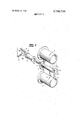
- FIG. 2 is a perspective exploded view of the wrap detector of FIG. 1;
- FIG. 3 is an end view of FIG. 2 and shows yarn wrap built up on rollers.
- the wrap detector 1 is mounted between two rollers 2 and 3 around which a number of turns of yarn 4 may be passed.
- the two rollers are driven in the directions of the arrows.
- the wrap detector 1 comprises a sensing member in the form of two plates 5 and 6 having edges 7 and 8 lying adjacent to the surfaces of rollers 2 and 3 respectively.
- the two plates are joined by a hollow sleeve 9 which is pivotally mounted on a shaft 10.
- a disc 11 is secured to one end of the sleeve 9, and a weight 12 is secured to the disc 11. Also secured to the disc 11 is a bush 13 of non-magnetic material to which is secured a permanent magnet 14.
- the assembly of the plates 5 and 6, sleeve 9, disc 11, weight 12, bush l3 and magnet 14 is such that it is all capable of pivotal movement as a unit about the shaft 10.
- the permanent magnet 14 normally lies against a stop pin 15 of ferromagnetic material. Positioned adjacent to the magnet 14 when in a deflected position 14b is a reed switch 16 electrically connected to a conventional yarn cutter and holder 17 in advance of roller 1.
- the thickness of yarn on the roller will deflect the sensing member anticlockwise as seen in F IG. 3.
- the deflection will increase as the thickness of the wrap increases, until the deflection reaches the end of the limited range of angular deflection, with the plates in positions 5a and 6a.
- the moment due to the weight 12 will apply to the sensing member an anticlockwise couple greater than the clockwise couple applied by attraction of the magnet 14 to the stop pin 15, and the sensing member will swing anticlockwise away from the rollers to a limit position indicated by broken lines 5b, 6b in the drawing.
- a stop (not shown) is provided to hold the sensing member in this limit position.
- the magnet 14 moves to position 14b and operates the reed switch 16 to affect the yarn feed.
- the reed switch controls the yarn cutter 17 ahead of the roller 1 so that when a wrap occurs the yarn is cut and held at the cutter 17 and no further yarn is fed to the roller.
- the yarn cutter may be of any desired type, and in particular may be a conventional knife arrangement or, particularly if handling thermoplastic yarn, may be an electrically heated wire movable into contact with the yarn.
- the switch 16 may act to stop the apparatus altogether. It will be seen that until the sensing member is positively reset by an operator to its normal position the reed switch 16 remains operated and normal operation of the apparatus can not be restarted, since the yarn cutter is held in its cutting position or the apparatus is stopped. On restarting, threading of yarn over the rollers is easy, since the wrap detector in its normal position does not lie adjacent to the yarn path.
- a yarn wrap detector according to the invention, and this can be varied in many ways.
- the detector can, of course be used to detect a wrap on a single roller, when one of the plates 5 or 6'may be omitted.
- the value of the weight and/or the strength of the magnet would then have to be changed to give the necessary operating limits.
- Latch and bias arrangements other than the magnet and weight shown can be used, and the reed switch may be replaced by a microswitch or photoelectric switch.
- the arrangement shown is of a particularly robust and simple nature and can therefore be manufactured cheaply to give long service.
- the wrap detector as described is particularly suitable for use in a yarn heater wherein heater plates such as 18 lie one to each side of the space between two rollers.
- a wrap detector for detecting a yarn wrapon a roller comprising a pivotally mounted sensing member arranged adjacent to the surface of said roller and having a predetermined normal position relative to said roller, means associated with said sensing member for allowing a limited range of angular deflection of said sensing member from said normal position, means, operative when said limited range is exceeded, for moving said sensing member through a greater angle to a limit position lying well clear of said roller and said yarn wrap, and switch means actuated by said allowing means when in said limit position for controlling further yarn feed.
- a wrap detector according to claim 1 including a stop member of ferromagnetic material, and a magnet fixed to move with said sensing member, said sensing member being held in its normal position by engagement of said magnet with said top member.
- a wrap detector according to claim 1 in which a weight is mounted to move with the sensing member, said weight being so positioned and of such value that immediately when said sensing member has moved to the end of said limited range said weight causes said sensing member to move on to said limit position.
- a wrap detector according to claim 2 in which said switch means is a reed switch actuated by said magnet when said sensing member is in its limit position.
- a wrap detector according to claim 1 in which said wrap detector is mounted between two rollers having ting the yam and arresting feed of yarn to the roller.
Landscapes
- Engineering & Computer Science (AREA)
- Textile Engineering (AREA)
- Mechanical Engineering (AREA)
- Quality & Reliability (AREA)
- Looms (AREA)
- Filamentary Materials, Packages, And Safety Devices Therefor (AREA)
- Spinning Or Twisting Of Yarns (AREA)
- Treatment Of Fiber Materials (AREA)
Applications Claiming Priority (1)
| Application Number | Priority Date | Filing Date | Title |
|---|---|---|---|
| GB2886971A GB1388838A (en) | 1971-06-19 | 1971-06-19 | Yarn wrap detectors |
Publications (1)
| Publication Number | Publication Date |
|---|---|
| US3790728A true US3790728A (en) | 1974-02-05 |
Family
ID=10282473
Family Applications (1)
| Application Number | Title | Priority Date | Filing Date |
|---|---|---|---|
| US00257785A Expired - Lifetime US3790728A (en) | 1971-06-19 | 1972-05-30 | Yarn wrap detector assembly with butterfly type sensor and switch actuator |
Country Status (10)
| Country | Link |
|---|---|
| US (1) | US3790728A (enExample) |
| BE (1) | BE784723A (enExample) |
| BR (1) | BR7203895D0 (enExample) |
| CH (1) | CH548938A (enExample) |
| DE (1) | DE2229801A1 (enExample) |
| ES (1) | ES403934A1 (enExample) |
| FR (1) | FR2143028B1 (enExample) |
| GB (1) | GB1388838A (enExample) |
| IT (1) | IT959165B (enExample) |
| NL (1) | NL7207861A (enExample) |
Cited By (2)
| Publication number | Priority date | Publication date | Assignee | Title |
|---|---|---|---|---|
| CN101448726B (zh) * | 2006-05-18 | 2012-01-18 | 欧瑞康纺织有限及两合公司 | 输送装置 |
| USD989817S1 (en) * | 2021-10-20 | 2023-06-20 | Btsr International Sp.A. | Textile thread control sensor for automatic textile knitting or sewing machines |
Citations (6)
| Publication number | Priority date | Publication date | Assignee | Title |
|---|---|---|---|---|
| US2637115A (en) * | 1950-04-03 | 1953-05-05 | Christensen Machine Co | Magnetic calipering device |
| US3247662A (en) * | 1963-01-05 | 1966-04-26 | Rieter Ag Maschf | Device for checking the run of the thread in a draw twisting frame or the like |
| US3364669A (en) * | 1965-03-23 | 1968-01-23 | Barmag Barmer Maschf | Shut off deivce for stretch twist machines |
| US3385493A (en) * | 1964-03-02 | 1968-05-28 | Deering Milliken Res Corp | Apparatus to control the speed of a fabric handling machine |
| US3389869A (en) * | 1965-03-03 | 1968-06-25 | Akai Electric | Tape drive motor control arrangement |
| US3462569A (en) * | 1967-07-31 | 1969-08-19 | Robert W Schooley | Sensing switch systems |
-
1971
- 1971-06-19 GB GB2886971A patent/GB1388838A/en not_active Expired
-
1972
- 1972-05-30 US US00257785A patent/US3790728A/en not_active Expired - Lifetime
- 1972-06-09 NL NL7207861A patent/NL7207861A/xx unknown
- 1972-06-12 BE BE784723A patent/BE784723A/xx unknown
- 1972-06-15 CH CH892872A patent/CH548938A/fr not_active IP Right Cessation
- 1972-06-16 FR FR727221728A patent/FR2143028B1/fr not_active Expired
- 1972-06-16 IT IT68945/72A patent/IT959165B/it active
- 1972-06-16 BR BR3895/72A patent/BR7203895D0/pt unknown
- 1972-06-16 ES ES403934A patent/ES403934A1/es not_active Expired
- 1972-06-19 DE DE2229801A patent/DE2229801A1/de active Pending
Patent Citations (6)
| Publication number | Priority date | Publication date | Assignee | Title |
|---|---|---|---|---|
| US2637115A (en) * | 1950-04-03 | 1953-05-05 | Christensen Machine Co | Magnetic calipering device |
| US3247662A (en) * | 1963-01-05 | 1966-04-26 | Rieter Ag Maschf | Device for checking the run of the thread in a draw twisting frame or the like |
| US3385493A (en) * | 1964-03-02 | 1968-05-28 | Deering Milliken Res Corp | Apparatus to control the speed of a fabric handling machine |
| US3389869A (en) * | 1965-03-03 | 1968-06-25 | Akai Electric | Tape drive motor control arrangement |
| US3364669A (en) * | 1965-03-23 | 1968-01-23 | Barmag Barmer Maschf | Shut off deivce for stretch twist machines |
| US3462569A (en) * | 1967-07-31 | 1969-08-19 | Robert W Schooley | Sensing switch systems |
Cited By (2)
| Publication number | Priority date | Publication date | Assignee | Title |
|---|---|---|---|---|
| CN101448726B (zh) * | 2006-05-18 | 2012-01-18 | 欧瑞康纺织有限及两合公司 | 输送装置 |
| USD989817S1 (en) * | 2021-10-20 | 2023-06-20 | Btsr International Sp.A. | Textile thread control sensor for automatic textile knitting or sewing machines |
Also Published As
| Publication number | Publication date |
|---|---|
| IT959165B (it) | 1973-11-10 |
| GB1388838A (en) | 1975-03-26 |
| ES403934A1 (es) | 1975-05-16 |
| DE2229801A1 (de) | 1973-01-11 |
| CH548938A (fr) | 1974-05-15 |
| BR7203895D0 (pt) | 1973-06-12 |
| NL7207861A (enExample) | 1972-12-21 |
| BE784723A (fr) | 1972-10-02 |
| FR2143028A1 (enExample) | 1973-02-02 |
| FR2143028B1 (enExample) | 1973-07-13 |
Similar Documents
| Publication | Publication Date | Title |
|---|---|---|
| US4420151A (en) | Overlapping feed detection device in sheet-processing machine | |
| US3790728A (en) | Yarn wrap detector assembly with butterfly type sensor and switch actuator | |
| GB2092630A (en) | Method and apparatus for preventing abnormal splicing in a yarn winder | |
| US4075445A (en) | Thread monitoring switch for textile machines having magnet biasing lever to prevent any annoying thread flutter | |
| US3859649A (en) | Web sensing apparatus | |
| US3521265A (en) | Electromagnetic toggle filament tension monitoring device | |
| US4915323A (en) | Yarn feed apparatus | |
| US3256395A (en) | Operator safety device for rotating machinery parts | |
| US2237341A (en) | Circuit controller for tentering machines | |
| US3402269A (en) | Apparatus for the detection of broken yarn and the like on textile machines | |
| US3132407A (en) | Cutting mechanism for use in an electronic yarn cleaner | |
| US4472932A (en) | Thread guard for spinning or twisting machine | |
| US3643883A (en) | Lap-detecting stop motion | |
| US3166651A (en) | Feeler device for moving runs of sheet material | |
| US3509739A (en) | Stop motion for a knitting machine | |
| US3364669A (en) | Shut off deivce for stretch twist machines | |
| US3880000A (en) | Method and apparatus for monitoring and controlling ambulant strip materials, especially suitable for use in the manufacture of insulators for inductive devices | |
| US3380134A (en) | Device for detecting flaws on running threads | |
| US3315047A (en) | Filament break detector | |
| US3689716A (en) | Magnetic stop motion device | |
| US3748414A (en) | Self-calibrating seam detector | |
| US3481550A (en) | Stop motion for yarn winding machine | |
| US3650128A (en) | Stop motion control device for knitting machines | |
| US3153273A (en) | Slub catchers for yarn spinning, doubling and similar machines | |
| US3023656A (en) | Cutting device |