US3789643A - Double angle cutoff die and method for rolling screws - Google Patents
Double angle cutoff die and method for rolling screws Download PDFInfo
- Publication number
- US3789643A US3789643A US00225242A US3789643DA US3789643A US 3789643 A US3789643 A US 3789643A US 00225242 A US00225242 A US 00225242A US 3789643D A US3789643D A US 3789643DA US 3789643 A US3789643 A US 3789643A
- Authority
- US
- United States
- Prior art keywords
- workpiece
- ramp
- cutoff
- plane
- die
- Prior art date
- Legal status (The legal status is an assumption and is not a legal conclusion. Google has not performed a legal analysis and makes no representation as to the accuracy of the status listed.)
- Expired - Lifetime
Links
Images

Classifications
-
- B—PERFORMING OPERATIONS; TRANSPORTING
- B21—MECHANICAL METAL-WORKING WITHOUT ESSENTIALLY REMOVING MATERIAL; PUNCHING METAL
- B21H—MAKING PARTICULAR METAL OBJECTS BY ROLLING, e.g. SCREWS, WHEELS, RINGS, BARRELS, BALLS
- B21H3/00—Making helical bodies or bodies having parts of helical shape
- B21H3/02—Making helical bodies or bodies having parts of helical shape external screw-threads ; Making dies for thread rolling
- B21H3/06—Making by means of profiled members other than rolls, e.g. reciprocating flat dies or jaws, moved longitudinally or curvilinearly with respect to each other
Definitions
- a full pre- Field of Search cisely formed gimlet point is achieved by means of an /643 extruding cutoff ramp having a high rate of penetration initially followed by a more gradual penetration [5 6] 1 References Cited to remove the extrusion slug.
- the field of this invention pertains to methods and tools for rolling threads on workpieces as they pass between a pair of elongated generally planar dies which are relatively displaced to produce surface material flow on the workpiece to form a continuous thread. More particularly, the invention pertains to means for rolling gimlet point screws utilizing a single multiplane face of each of the two dies- These dies allow the use of straight, i.e., cylindrical blanks to be used as opposed to blanks having preformed points. The use of such dies reduces the headed blank costs as well as the size of blank inventories.
- the present invention has been found to be most useful with respect to flat rolling dies in conventional thread rolling machines.
- the shorter of a pair of dies is ordinarily held stationary while the longer die is moved in a direction parallel to a longitudinal reference plane in which the axis of rotation of the body portion of the workpiece travels as the workpiece rolls between the pair of dies.
- Ordinarily no appreciable axial movement of the workpiece occurs during the rolling operation.
- the diameter of the finished thread is controlled by the diameter of the blank and the distance between the dies at the finish end of the stroke.
- the workpiece typically will be steel although any extrudable commerciallyemployed material may be used.
- Another problem which has occurred with such designs is that the movement of metal with some materials is sufficiently slow to create a work hardening effect that impedes subsequent formations. This problem is most acute in the formation of gimlet points since such points are formed after the body threads have begun to be formed. It is also most acute with certain materials that are particularly vulnerable to work hardening such as 300 series stainless steel or C-l022 carbon steel which, because of its manganese composition, is more vulnerable to work hardening.
- a primary object of this invention is to provide dies for rolling and a method for rolling gimlet point screws wherein full points and point thread formations are consistently produced.
- Another object of the present invention is to provide dies which are of minimum length and which minimize cold working effects on the screw blank.
- Still another object is to provide amethod and an apparatus wherein the slug cutoff is delayed until a relatively full, sharp .point is produced.
- a further object of the invention is to gradually urge a slug of excess material away from the screw point during the final forming and threading thereof.
- the dies have a first surface for forming the cylindrical workpiece having a mean or average plane which will be coincident with the first surface if the surface is planar.
- a cutoff ramp is disposed in upstanding relationship to the mean plane for severing the, cylindrical workpiece having a first plane inclined at a first angle to the mean plane and a second plane inclined at a second angle to the mean plane. The angles will always be different although most preferably the first angle is greater than the second angle.
- the dies have a generally planar second surface extending between the first surface and the cutoff ramp.
- the second surface is obliquely disposed with respect to the mean plane to form a pointed surface on a workpiece adjacent to the end formed when the cutoff ramp severs the cylindrical workpiece.
- the cutoff ramp penetrates into the workpiece three quarters of its total penetration in the first one-half of its length which contacts the workpiece. In another preferred form the cutoff ramp penetrates seven-eights of its maximum penetration into the workpiece after three quarters of the length of the cutoff ramp has passed over the cylindrical workpiece.
- the invention also contemplates the method of severing the end of a cylindrical workpiece comprising urging a first portion of an upstanding cutoff ramp having a generally planar outer face against one longitudinal portion of the cylindrical workpiece as it is rotated, and then urging a second portion of the cutoff ramp inclined at a different angle than the first portion against the one longitudinal portion of said cylindrical workpiece so that the rate of penetration into the cylindrical workpiece vaires between the first and second portions.
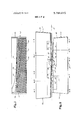
- FIG. 1 is a top plan view to a greatly enlarged scale of the short die of a pair of thread rolling dies in accordance with the invention
- FIG. 2 is a side elevational view to a greatly enlarged scale of a pair of thread rolling dies consisting of the short die in FIG. 1 together with a long die in the matched position with a screwblank therebetween;
- FIG. 3 is a top plan view to a greatly enlarged scale of the die shown in FIG. 1 before ridges and traction notches have been formed therein showing the planar faces on the top surface of the die more clearly;
- FIG. 4 is a transverse sectional view to a greatly enlarged scale taken along the line 4-4 of FIG. 2 when these lines on the upper and lower dies are in vertical alignment prior to horizontal movement of the long die to the left as viewed to the FIG. 2 position and with a diameter of the workpiece alignedgwith the section lines but with the threads omitted to more clearly show the extruding action of the dies in forming the gimlet point;
- FIG. 5 is a transverse sectional view to a greatly enlarged scale taken along the line 5-5 of FIG. 2 when these section lines on the upper and lower dies are in vertical alignment prior to horizontal movement of the long die to the left as viewed to the FIG. 2 position and with a diameter of the workpiece aligned with these lines but with the threads omitted to more clearly show the extruding action of the dies in forming the gimlet point;
- FIG. 6 is a transverse sectional view to a greatly enlarged scale taken along the line 66 of FIG. 2 when these section lines on the upper and lower dies are in vertical alignment prior to horizontal movement of the long die to the FIG. 2 position and with a diameter of the workpiece aligned with the section lines but with the threads omitted to more clearly show the formation of the gimlet point;
- FIG. 7 is a transverse sectional view to a greatly enlarged scale taken along the line 77 of FIG. 2 when these section lines on the upper and lower dies are in vertical alignment after horizontal movement of the upper die from the FIG. 2 position and with a diameter of the workpiece aligned with these section lines but with the threads omitted to more clearly show the point formation;
- FIG. 8 is a transverse sectional view to a greatly enlarged scale taken along the line 88 of FIG. 2 when these section lines on the upper and lower dies are in vertical alignment after horizontal movement of the upper die from the FIG. 2 position and with a diameter of the workpiece aligned with these section lines but with the threads omitted to more clearly show the point formation.
- FIGS. 1, 2 and 30f therein illustrated is a short die 10 embodying the present invention and having a plurality of discrete regions, each of which is adapted to operate in conjunction with a corresponding region on a long die 12 to vary the form of a blank or workpiece 14 having a cylindrical body portion 16 and a head 18.
- a long die 12 As is customary in such dies, there is an exact counterpart having identical shape and size on the long die for every portion of the short die except the end portions.
- the long die 12 is provided with extensions which typically may be one quarter of one inch on each end. The extensions are provided for end-wise adjustment purposes.
- the discrete transverse regions of short die 10 are identified by letters A through F.
- the workpiece 14 is rolled from region B on short die 10 and long die 12 to region E on short die 10 and long die 12.
- Regions A and F are the sloping end portions by which the die is mounted.
- Region B is the point relief area in which the screw blank is first positioned between the dies.
- Region C includes the cutoff or extruding ramp first plane 20 in which the ramp penetrates the workpiece cylindrical portion 16 at a high rate.
- region D the angle of incidence of the cutoff ramp with respect to the workpiece is altered and a cutoff ramp second plane 22 thereof continues to penetrate the workpiece at a lower rate. The end of the cutoff ramp occurs at the end of region D at which time the extrusion slug 23 is fully formed although not yet severed from the cylindrical body portion 16 of the workpiece.
- FIG. 7 best illustrates this action.
- region E the point threading surface 24, which started in region C, continues to fully form the threads on the gimlet point which has been fully formed at the end of region D.
- a planar land surface 26 is parallel to the base 27 of the short die 10 as well as to plane Z which is defined by the successive positions of the longitudinal axis of the cylindrical portion 16 of blank 14. This surface 26 provides the final severance of the extrusion slug 23 as the corresponding surface 26 from the long die bears against it and increases in width as the workpiece cylindrical portion 16 passes therebetween.
- the body threading surface 28 extends through regions B, C D and E and provides for threading of the body in a conventional manner.
- Back taper portion 30 is provided to urge the extrusion slug 23 away from the pair of dies 10 and 12.
- Back cut surface 32 is cut away to provide an area for the extrusion slug 23 to drop away.
- Region E is the finish dwell and rolloff area which is provided to guide the fully formed screw away from the dies 10 and 12.
- the first plane 20 of the extruder or cutoff ramp is substantially trapezoidal having converging sides 34 and 36 as well as a side 38 which is substantially parallel to the fourth side which is not illustrated in the drawings although it is coextensive with a line perpendicular to the longitudinal center line of the short die 10 and separating regions B and C.
- Surface 40 is coplanar with cutoff ramp first plane 20 but is considered a discrete surface because the cutoff or extrusion has not yet begun which forms the gimlet point as is apparent by reference to FIG. 4. It will be observed there that the cylindrical surface 16 of the workpiece 14 has not yet been deformed although it is gripped by the body threading portion 28.
- the body threading portion 28 is provided with a plurality of ridges 42 which form the body threads on the workpiece 14 as well as a plurality of crossnicks or traction notches as described in Orlomoski US. Pat. No. 3,405,545 having the same assignee as the present invention.
- the traction notches avoid slippage of the workpiece with respect to the die during the rolling operation.
- the body threading portion 28 lies between the edge 46 of the top surface of the die and heel line 48 which defines the intersection between the body threading surface 28 and the point threading surface 24.
- Surface 24 is bounded on the opposite side by edge 34 of cutoff ramp first plane 20, edge 50 of cutoff ramp second plane 22 and edge 52 of surface 26. Ridges 54 are provided on the point threading surface 24 in the conventional manner.
- the body threading surface 28 is disposed substantially parallel to the base 27 of short die 10.
- Point threading surface 24 is disposed at an angle corresponding to the angle of the gimlet point of the screw as is best seen by reference to FIGS. 5 through 8. The angle will not change throughout the length of the point threading surface 24 although as is most evident in FIG. 3 the width of this surface will vary.
- Extrusion ramp first plane 20 forms an angle with reference plane Z and also base 27 which is most evident in FIG. 2 wherein edges 34 and 36 are clearly shown. It will be seen that an angle is formed between reference plane Z and extruder ramp first plane 20 when short die 10 is viewed lengthwise as in FIG. 2. The size of this angle will be discussed hereafter. It is also evident from FIG. 2 that viewing the end of die 10 that the extrusion ramp first plane 20 is canted at an angle. Th'at angle which tends to force the extrusion slug 23 away fromthe cylindrical surface 16 of the workpiece 14 will normally be less than twenty degrees.
- the cutoff ramp second plane 22 will have an angle with respect to reference plane Z which when viewed from the end'of short die will also normally be less than 20.
- the angle of this same surface when viewed from the side as in FIG. 2 is indicated by the edges shown in that view.
- Both the cutoff ramp first plane 20 and second plane 22 are providedwithtraction notches 58 which are desirable to insure that the extrusion slug 23 is forced to rotate with the cylindrical portion 16 of the workpiece 14.
- the land surface 26 has diverging edges 52 and 60 which urge the extrusion slug 23 away from the cylindrical portion 16 after the extrusion slug 23 has been fully formed..
- the land surface 26 is-normally substantially parallel to reference plane Z and the sides thereof diverge at an angle of approximately fifteen degrees.
- the back taper portion 30 of the die is adjacent to the land surface 26 and is also bounded by an arcuate portion 62 of the back cut surface 32.
- Oblique end surfaces 66, 68 are provided on short die 10 for gripping by the thread rolling machine.
- oblique ends 70, 72 are provided on long die 12 for gripping by the thread rolling machine.
- the cutoff ramp extends the length of regions C and D. Stated another way, the cutoff ramp extends the length of extrusion ramp first plane 20 and extrusion ramp second plane 22.
- the total length ordinarily corresponds to about three complete turns of the workpiece 14. It should be understood however that the length may vary and that a length corresponding to as manyas five turns may be provided with the length being largely dependent upon the size of the screw being rolled and the positioning of the holders for the dies in the thread rolling machine being used.
- the length of the cutoff ramp may also be defined asthe length of the top surface (regions B, C, D and E) less the length-of the point .relief area (region B) and the length of the dwell and rolloff area (region E).
- Region E is normally equal in length to one to one and one-half blank circumferences plus the length of rolloff.
- the length of rolloff will normally be about one screw major diameter.
- Region B is the length of point relief which normally will be fixed for any one size of die.
- the length corresponding to specific dies which are normally used are No. 00 3/16 inch, No. 0 3 1 inch, No. 10 inch, and No. 20 4 inch. It will be understood by those skilled in the art that normally any one rolling machine will hold only one length of die and also that any one die may be used for a number of sizes. Accordingly, the number of blank circumferences equal to the cutoff ramp length will vary when different sizes of blanks are rolled on the same die.
- the distance between the projection of the heel line 48 and point 74 corresponds to the point constant of the gimlet point screw being rolled.
- the point constant of thegimlet point screw is the longitudinal distance between the extreme tip of the point and the end of sloping surfaces leading away from the point. This dimension has been labeled PC in FIG. 8.
- the distance between the projection of point 74 and heel line 48 on a' vertical plane 'as in FIG. 2 is known as the height of curve.
- the ratio of l) the vertical distance of any point on edge 50 or 34 to the heel line 48 to (2) the horizontal distance of that point on edge 50 or 34 to the heel line 48 is equal the ratio of the height of curve and point constant.
- the dimensions of the point constant and the height of curve dimensions of the die are fixed. Other variations in the cutoff ramp are a matter of the designers choice.
- edge 34 of cutoff ramp first plane 20 is diverging rapidlyfrom heel line 48 in region C as projected in a horizontal plane such as FIG. 2. It is also diverging from heel line 48 as projected in a vertical plane, as in FIG.
- edges 34 and 50 intersect at apoint which is three-fourths of the length of the cutoff ramp with seven-eighths of the point constant.
- the cutoff ramp innersurface penetrates seven-eighths of the point constant in threefourths of the length of the cutoff ramp.
- the size that is most desirable will vary with the size of the screw being rolled. More particularly, this latter embodiment has been found particularly satisfactory with No. 12 screw diameters as well as larger sizes. The first embodiment has been most successful with No. 0 through No. 10 screw diameters.
- the long die 12 is provided with an exact counterpart having identical shape in size of each portion of the short die with the exception that extensions which typically may be in the order of one quarter of an inch are provided which increase the length of the pointrelief area (region B) and the finish relief area (region E).
- the lengths of regions C and D in short die 10 and long die 12 are identical and the distances between the section shown in FIGS. 4, 5, 6, 7 and 8 are identical in the'two dies.
- FIGS. 4, 5, 6, 7 and 8 the functioning of the short die 10 in cooperation with the long die 12will be more apparent.
- the workpiece 14 is fed between body threading surfaces 28 of short die 10 and long die 12.
- FIG. 4 as well as FIGS. 5,6, 7 and 8 have been simplified by eliminating the threads to show in greater detail the point forming action of the dies.
- As'long die 12 is longitudinally displaced, the workpiece is passed from region B to region C and specifically to the position shown in FIG. wherein point threading surface 24 has started and as will be apparent in succeeding sectional views and also from FIG. 3 that surface is increasing its contact with the cylindrical surface 16 of the workpiece 14.
- the cutoff ramp 20 has begun to contact a portion of the cylindrical body portion 16 of the workpiece 14 and has begun to form the extrusion slug 23 and to urge it away from the head 18 of the workpiece 14.
- FIG. 6 is shown the operation of the various surfaces of the dies 10 and 12 at a point shortly after the workpiece 14 has been rolled into region D. It will be seen that the bulk of the extrusion slug 23 has been formed and that most of the point of the workpiece has also been formed by point threading surfaces 24. The penetration of the cutoff ramp first plane has been completed at this cross-sectional point, and it is most apparent that the bulk of its penetration into the workpiece 14 cylindrical portion 16 has occurred at this cross-sectional position.
- this angle may vary throughout the length of the extruder ramp and may for example be initially 15 and then may be increased to 20 at a point of later contact with the workpiece particularly in the area near where the extrusion slug 23 is severed. Many of the other surfaces may be varied to a substantial degree without departing from the invention.
- the present invention provides a highly effective cutoff die and method for rolling screws which is capable of forming full points and point thread formations in a consistent manner.
- the dies by combining a cutoff ramp having a rapid rate of penetration or initial formation initially followed by a slow or final rate of penetration or final formation provide the full point without the necessity for an extremely long die which would otherwise be necessary to accomplish the desired result and which would produce undesirable cold working effects.
- the slower rate of final penetration or formation gradually urges the extrusion slug away from the screw point during the final forming and threading thereof.
- a roll forming die for forming the circumference of a cylindrical workpiece and for pointing and severing the cylindrical workpiece wherein the die is provided with (a) a first surface for forming a body portion of a cylindrical workpiece, said first surface having a mean plane and (b) a cutoff ramp upstanding from said mean plane for pointing and severing the cylindrical workpiece, said cutoff ramp rising from said first surface of the die for forming the workpiece and having a first plane inclined at a first angle to said mean plane and a second plane inclined at a second angle to said mean plane, said second angle being different than said first angle, said cutoff ramp having a point threading surface on the side thereof between said mean plane and the uppermost portion of said cutoff ramp.
- a roll forming die as set forth in claim 2 wherein a generally planar second surface extends between said first surface and said cutoff ramp, said second surface being obliquely disposed with respect to said mean plane to form a pointed surface on the workpiece adjacent to the end formed when said cutoff ramp severs the cylindrical workpiece.
- a roll forming die as set forth in claim 4 wherein said first plane engages said workpiece before the second plane and said cutoff ramp penetrates into the workpiece three quarters of its total penetration in the first one-half of its length which contacts the workpiece.
- a pair of roll forming dies for forming the circumference of a cylindrical workpiece and for pointing and severing the cylindrical workpiece wherein each die is provided with (a) a first surface for forming a body portion of a cylindrical workpiece, said first surface having a mean plane and (b) a cutoff ramp upstanding from said mean plane for pointing and severing the cylindrical workpiece, said cutoff ramp rising from said first surface of the die for forming the workpiece and having a first plane inclined at a first angle to said mean plane and a second plane inclined at a second angle to said mean plane, said second angle being different than said first angle, said cutoff ramp having a point threading surface on the side thereof between said mean plane and the uppermost portion of said cutoff ramp.
- each of said dies has a generally planar second surface extending between said first surface and said cutoff ramp, each of said second surfaces being obliquely disposed with respect to said mean plane to fonn a pointed surface on said workpiece adjacent to the end formed when said cutoff ramp severs the cylindrical-workpiece.
Landscapes
- Engineering & Computer Science (AREA)
- Mechanical Engineering (AREA)
- Forging (AREA)
- Extrusion Moulding Of Plastics Or The Like (AREA)
Applications Claiming Priority (1)
| Application Number | Priority Date | Filing Date | Title |
|---|---|---|---|
| US22524272A | 1972-02-10 | 1972-02-10 |
Publications (1)
| Publication Number | Publication Date |
|---|---|
| US3789643A true US3789643A (en) | 1974-02-05 |
Family
ID=22844118
Family Applications (1)
| Application Number | Title | Priority Date | Filing Date |
|---|---|---|---|
| US00225242A Expired - Lifetime US3789643A (en) | 1972-02-10 | 1972-02-10 | Double angle cutoff die and method for rolling screws |
Country Status (4)
| Country | Link |
|---|---|
| US (1) | US3789643A (it) |
| JP (1) | JPS5334580B2 (it) |
| DE (1) | DE2306431A1 (it) |
| GB (1) | GB1415404A (it) |
Cited By (5)
| Publication number | Priority date | Publication date | Assignee | Title |
|---|---|---|---|---|
| US3857273A (en) * | 1973-06-22 | 1974-12-31 | Ex Cell O Corp | Toothed forming tool |
| US4563890A (en) * | 1984-01-27 | 1986-01-14 | Litton Industrial Products, Inc. | Cut-off style, roll thread flat dies |
| WO1999007496A1 (en) * | 1997-08-08 | 1999-02-18 | Pcc Specialty Products, Inc. | Flat thread rolling die for pointed screws |
| US6171042B1 (en) | 1997-12-19 | 2001-01-09 | Illinois Tool Works Inc. | Hardened steel pin, pin and washer fastener, washer for fastener, and pin-making method |
| US20070178979A1 (en) * | 2002-03-26 | 2007-08-02 | Bechtel Frank W Jr | Radius gimlet point anti-stripout screw |
Families Citing this family (3)
| Publication number | Priority date | Publication date | Assignee | Title |
|---|---|---|---|---|
| JPS5268842A (en) * | 1975-12-05 | 1977-06-08 | Manpei Seisakushiyo Kk | Wood screw die plate |
| DE102008045302A1 (de) | 2007-11-14 | 2009-05-20 | E. W. Menn Gmbh & Co. Kg | Gewinde- und Profilwalzmaschine |
| EP2095892A1 (de) | 2008-02-27 | 2009-09-02 | E. W. Menn Gmbh & Co. Kg | Profilwalzmaschine |
Citations (4)
| Publication number | Priority date | Publication date | Assignee | Title |
|---|---|---|---|---|
| US3176491A (en) * | 1958-01-13 | 1965-04-06 | Nat Rolled Thread Die Co | Thread and other form rolling dies |
| US3217530A (en) * | 1963-01-02 | 1965-11-16 | Katayama Rivet & Screw Ind Co | Die blocks for thread rolling machines |
| US3538739A (en) * | 1968-04-01 | 1970-11-10 | Reed Rolled Thread Die Co | Thread rolling die with cylindrical slug forming and removal surface |
| US3726171A (en) * | 1970-10-09 | 1973-04-10 | Imp Eastman Corp | Tube cutter |
-
1972
- 1972-02-10 US US00225242A patent/US3789643A/en not_active Expired - Lifetime
-
1973
- 1973-02-01 GB GB510173A patent/GB1415404A/en not_active Expired
- 1973-02-09 DE DE2306431A patent/DE2306431A1/de not_active Ceased
- 1973-02-09 JP JP1640173A patent/JPS5334580B2/ja not_active Expired
Patent Citations (4)
| Publication number | Priority date | Publication date | Assignee | Title |
|---|---|---|---|---|
| US3176491A (en) * | 1958-01-13 | 1965-04-06 | Nat Rolled Thread Die Co | Thread and other form rolling dies |
| US3217530A (en) * | 1963-01-02 | 1965-11-16 | Katayama Rivet & Screw Ind Co | Die blocks for thread rolling machines |
| US3538739A (en) * | 1968-04-01 | 1970-11-10 | Reed Rolled Thread Die Co | Thread rolling die with cylindrical slug forming and removal surface |
| US3726171A (en) * | 1970-10-09 | 1973-04-10 | Imp Eastman Corp | Tube cutter |
Cited By (8)
| Publication number | Priority date | Publication date | Assignee | Title |
|---|---|---|---|---|
| US3857273A (en) * | 1973-06-22 | 1974-12-31 | Ex Cell O Corp | Toothed forming tool |
| US4563890A (en) * | 1984-01-27 | 1986-01-14 | Litton Industrial Products, Inc. | Cut-off style, roll thread flat dies |
| WO1999007496A1 (en) * | 1997-08-08 | 1999-02-18 | Pcc Specialty Products, Inc. | Flat thread rolling die for pointed screws |
| US6171042B1 (en) | 1997-12-19 | 2001-01-09 | Illinois Tool Works Inc. | Hardened steel pin, pin and washer fastener, washer for fastener, and pin-making method |
| US6203442B1 (en) | 1997-12-19 | 2001-03-20 | Illinois Tool Works Inc. | Hardened steel pin, pin and washer fastener, washer for fastener, and pin-making method |
| US6305065B1 (en) | 1997-12-19 | 2001-10-23 | Illinois Tool Works Inc. | Method of assembling roof decking to an underlying substrate |
| US20070178979A1 (en) * | 2002-03-26 | 2007-08-02 | Bechtel Frank W Jr | Radius gimlet point anti-stripout screw |
| US7402109B2 (en) * | 2002-03-26 | 2008-07-22 | Illinois Tool Works Inc. | Radius gimlet point anti-stripout screw |
Also Published As
| Publication number | Publication date |
|---|---|
| JPS4889863A (it) | 1973-11-24 |
| GB1415404A (en) | 1975-11-26 |
| JPS5334580B2 (it) | 1978-09-21 |
| DE2306431A1 (de) | 1973-10-04 |
Similar Documents
| Publication | Publication Date | Title |
|---|---|---|
| US2239352A (en) | Setscrew and method of producing same | |
| US3318182A (en) | Self-thread-forming screw with drill point and method of making same | |
| US3878759A (en) | Bi-lobular self-thread forming fastener | |
| US3789643A (en) | Double angle cutoff die and method for rolling screws | |
| US3218656A (en) | Method of forming a self-tapping or thread-forming screw | |
| US3681963A (en) | Self-thread forming threaded fasteners and method and apparatus for making the same | |
| US3405545A (en) | Rolled thread die with traction notches | |
| US3461470A (en) | Thread-forming screw and method of making the same | |
| US3550255A (en) | Method of making rotary threaded fasteners | |
| US3176491A (en) | Thread and other form rolling dies | |
| US3803889A (en) | Self-thread forming threaded fasteners and method for making same | |
| DE1910549B2 (de) | Kontinuierlich arbeitende Keilquerwalzvorrichtung | |
| US3196654A (en) | Screw rolling die | |
| US387184A (en) | rogers | |
| US3538739A (en) | Thread rolling die with cylindrical slug forming and removal surface | |
| US2093646A (en) | Method of and apparatus for making cold formed socketed screws | |
| US3517542A (en) | Complementary finishing dies | |
| US3260100A (en) | Apparatus for simultaneously imparting an alternate series of thread forms on a workpiece | |
| US2314390A (en) | Method and apparatus for rolling screws | |
| US2079056A (en) | Method of making cap-screws | |
| US1946735A (en) | Screw rolling die and method | |
| US2150815A (en) | Screw-threaded stock and manufacture of same | |
| US3263473A (en) | Method and apparatus for making threaded fasteners | |
| US3481178A (en) | Thread rolling and rolled threaded objects | |
| US3255798A (en) | Weld nut and method of producing the same |
Legal Events
| Date | Code | Title | Description |
|---|---|---|---|
| AS | Assignment |
Owner name: QUAMCO, INC., 100 CONSTITUTION PLAZA, SUTE 1560, H Free format text: ASSIGNMENT OF ASSIGNORS INTEREST.;ASSIGNOR:LITTON INDUSTRIAL PRODUCTS, INC. A DE CORP.;REEL/FRAME:004324/0546 Effective date: 19841026 |
|
| AS | Assignment |
Owner name: LITTON INDUSTRIAL PRODUCTS, INC., 360 NORTH CRESCE Free format text: SECURITY INTEREST;ASSIGNOR:QUAMCO, INC.;REEL/FRAME:004342/0219 Effective date: 19841026 |
|
| AS | Assignment |
Owner name: LITTON INDUSTRIAL AUTOMATION SYSTEMS, INC. Free format text: MERGER;ASSIGNORS:KIMBALL SYSTEMS, INC.;LITTON INDUSTRIAL PRODUCTS INC.;LITTON DATAMEDIX, INC.;REEL/FRAME:004554/0550;SIGNING DATES FROM |
|
| AS | Assignment |
Owner name: CONNECTICUT BANK & TRUST COMPANY, N.A., 100 CONSTI Free format text: SECURITY INTEREST;ASSIGNOR:QUAMCO, INC.;REEL/FRAME:004839/0972 Effective date: 19880219 |
|
| AS | Assignment |
Owner name: HELLER FINANCIAL, INC. Free format text: SECURITY INTEREST;ASSIGNOR:QUAMCO, INC., A CORP. OF DE;REEL/FRAME:005454/0071 Effective date: 19891213 |