US3786934A - Carrier structure particularly for office equipment assembly - Google Patents
Carrier structure particularly for office equipment assembly Download PDFInfo
- Publication number
- US3786934A US3786934A US00236098A US3786934DA US3786934A US 3786934 A US3786934 A US 3786934A US 00236098 A US00236098 A US 00236098A US 3786934D A US3786934D A US 3786934DA US 3786934 A US3786934 A US 3786934A
- Authority
- US
- United States
- Prior art keywords
- carrier
- sleeves
- improvement
- columns
- hollow support
- Prior art date
- Legal status (The legal status is an assumption and is not a legal conclusion. Google has not performed a legal analysis and makes no representation as to the accuracy of the status listed.)
- Expired - Lifetime
Links
Images


Classifications
-
- A—HUMAN NECESSITIES
- A47—FURNITURE; DOMESTIC ARTICLES OR APPLIANCES; COFFEE MILLS; SPICE MILLS; SUCTION CLEANERS IN GENERAL
- A47B—TABLES; DESKS; OFFICE FURNITURE; CABINETS; DRAWERS; GENERAL DETAILS OF FURNITURE
- A47B21/00—Tables or desks for office equipment, e.g. typewriters, keyboards
- A47B21/06—Tables or desks for office equipment, e.g. typewriters, keyboards characterised by means for holding, fastening or concealing cables
-
- A—HUMAN NECESSITIES
- A47—FURNITURE; DOMESTIC ARTICLES OR APPLIANCES; COFFEE MILLS; SPICE MILLS; SUCTION CLEANERS IN GENERAL
- A47B—TABLES; DESKS; OFFICE FURNITURE; CABINETS; DRAWERS; GENERAL DETAILS OF FURNITURE
- A47B5/00—Suspended or hinged panels forming a table; Wall tables
-
- A—HUMAN NECESSITIES
- A47—FURNITURE; DOMESTIC ARTICLES OR APPLIANCES; COFFEE MILLS; SPICE MILLS; SUCTION CLEANERS IN GENERAL
- A47B—TABLES; DESKS; OFFICE FURNITURE; CABINETS; DRAWERS; GENERAL DETAILS OF FURNITURE
- A47B83/00—Combinations comprising two or more pieces of furniture of different kinds
- A47B83/001—Office desks or work-stations combined with other pieces of furniture, e.g. work space management systems
-
- E—FIXED CONSTRUCTIONS
- E04—BUILDING
- E04H—BUILDINGS OR LIKE STRUCTURES FOR PARTICULAR PURPOSES; SWIMMING OR SPLASH BATHS OR POOLS; MASTS; FENCING; TENTS OR CANOPIES, IN GENERAL
- E04H1/00—Buildings or groups of buildings for dwelling or office purposes; General layout, e.g. modular co-ordination or staggered storeys
- E04H1/06—Office buildings; Banks
-
- A—HUMAN NECESSITIES
- A47—FURNITURE; DOMESTIC ARTICLES OR APPLIANCES; COFFEE MILLS; SPICE MILLS; SUCTION CLEANERS IN GENERAL
- A47B—TABLES; DESKS; OFFICE FURNITURE; CABINETS; DRAWERS; GENERAL DETAILS OF FURNITURE
- A47B37/00—Tables adapted for other particular purposes
- A47B2037/005—Tables specially adapted for laboratories
-
- A—HUMAN NECESSITIES
- A47—FURNITURE; DOMESTIC ARTICLES OR APPLIANCES; COFFEE MILLS; SPICE MILLS; SUCTION CLEANERS IN GENERAL
- A47B—TABLES; DESKS; OFFICE FURNITURE; CABINETS; DRAWERS; GENERAL DETAILS OF FURNITURE
- A47B2200/00—General construction of tables or desks
- A47B2200/0066—Workstations
- A47B2200/0067—Enclosure type with computer
- A47B2200/0071—Booth like
Landscapes
- Engineering & Computer Science (AREA)
- Architecture (AREA)
- Civil Engineering (AREA)
- Structural Engineering (AREA)
- Tables And Desks Characterized By Structural Shape (AREA)
- Assembled Shelves (AREA)
- Special Chairs (AREA)
Abstract
Various items of work place equipment, such as a seat, desk, typewriter top, phone shelf, overhead illuminating structure and the like are supported by one or more vertical carrier columns each formed of an inner throughgoing hollow support post (adapted to receive electric conductors and the like), a plurality of carrier sleeves which surround the hollow support post and to which said items are secured (directly or by a cantilever) and a plurality of spacer sleeves for arbitrarily determining the height position of any carrier sleeve.
Description
United States Patent 1 1 1111 3,786,934 Burgin 1 1 Jan. 22, 1974 [541 CARRIER STRUCTURE PARTICULARLY 2,367,082 1/1945 Amidon et a1. 211/123 X FOR OFFICE EQUIPMENT ASS 2,521,355 9/1950 Ford 3,389,882 6/1968 Schlosser 211/177 X [76] Inventor: Gerard Burgin, 6, rue de la Thur,
Kingersheim France FOREIGN PATENTS OR APPLICATIONS 677,263 8/1952 Great Britain 211/148 [221 Flled: 201 1972 689,318 4/1965 ltaly 211/131 [21] Appl. No.: 236,098
Primary Examiner-Ramon S. Britts Art ,A t, F'm-Edi E.G [30] Foreign Application Priority Data omey gen or U w n relgg Mar. 18, 1971 Germany 2113113 [57] ABSTRACT 52 us. c1 211/182 211/26 211/168 items of wmk Place equipment Such as a 51 1m.c1..:..:..1.:......1 A471 5/00, A47f 7/00 Seat desk typewriler Phone Shelf Overhead of Search. minating structure and the are supported one 211/174 86 96 110 6 g or more vertical carrier columns each formed of an 0 4 715 inner throughgoing hollow support post (adapted to receive electric conductors and the like), a plurality of l 5 6] References Cited carrier sleeves which surround the hollow support post and to which said items are secured (directly or by a UNITED STATES PATENTS cantilever) and a plurality of spacer sleeves for arbi- Jordan trarily determining the position of any carrier 1,408,128 2/1922 Neahr..... Skew 1,804,912 5/1931 Anton..... 2,136,843 11/1938 Dinkel 211/78 x 11 Claims, 9 Drawing Figures s. kE I 1 as Q E PATENIEB JAN 2 2 I974 SHEEI 1 BF 7 Fig.1
PAIENTEU H 3,786,934
sum nor 7- PATENTED 3,786 994 SHEET 3 OF 7 Fig. 7
PNENTEB JAHZ 21974 saw s [If "g PATENTEB JAN 2 219% SHEET 7 BF 7 CARRIER STRUCTURE PARTICULARLY FOR OFFICE EQUIPMENT ASSEMBLY BACKGROUND OF THE INVENTION This invention relates to a carrier structure particularly for supporting a plurality of office items. The structure includes a throughgoing vertical hollow support post to which shelves, table tops, seats and the like are attached as cantilevers. The hollow support post is adapted to receive electric conductors and the like.
For the installation of exhibition booths and the like it is known to provide, between the ceiling and the floor, a hollow support post of quadratic cross section, the lateral walls of which are provided with openings for attaching thereto in a cantilever manner brackets of similar components, to which shelves or the like may be secured. It is also known to dispose electric conductors inside the said hollow support posts.
Structures of the aforenoted known type have a number of disadvantages.
Thus, the openings provided over the entire length and on all four sides of the hollow support post are esthetically unappealing. Further, the load capacity of the brackets secured by means of screws to the wall of the hollow support post is limited. Also, the items may be mounted only in four discrete positions. In addition, the internally disposed conductors are visible because of the openings in the wall of the hollow support post.
It is known to provide, particularly for phonographs or television sets, a hollow support (as disclosed in German Utility Model No. 1,960,030) which has the advantage that the components supported thereby may be brought into any desired angular position about a vertical axis. This structure, however, is relatively complicated. Thus, between take-up components attached to the ceiling and to the floor there are clamped at least two tubular members in which a frame is rotatably supported by means of pins. The apparatus to be supported is positioned in the frame. This known structure is thus adapted only to receive a single apparatus at a structurally predetermined definite height.
Further, telephone booth structures are known, as disclosed, for example, in U.S. Pat. No. 3,419,305, which may be positioned adjacent one another and which are formed essentially of three walls to which there is secured a seat by means ofa cantilever support. According to an embodiment, a central leg supports a plurality of such phone booths and also cantilevers secured to said central leg by bolts. The cantilevers support a seat in an articulated manner.
OBJECT SUMMARY AND ADVANTAGES OF THE INVENTION It is an object of the inveniton to provide a carrier structure of the aforeoutlined type which is formed of fewer parts, has an attractive appearance and permits the securing thereto of carrying surfaces, such as shelves or the like at practically any height and any angular position without expensive means and without limitation to their load carrying capacity.
Briefly stated, according to the invention, the items of equipment are affixed to sleeves which are mounted on and surround the hollow post mentioned hereinbefore. Between said sleeves (hereinafter referred to as carrier sleeves) there are disposed similarly structured spacer sleeves which also surround the hollow carrier post. The latter is of such a cross sectional dimension that it is adapted to receive the entire equipment required for each work place.
In principle, the hollow support post may have any desired cross section, since it is covered by the carrier and spacer sleeves which determine the appearance of the entire column structure. The provision of these sleeves also make it possible to attach the items of equipment at practically any height and since the load may be taken up through the spacer sleeves, the structure, according to the invention, is not limited in its load capacity as are prior art arrangements outlined hereinbefore. Further, the concealment of the hollow support post by the sleeves makes it possible to design the hollow post entirely in accordance with the requirements of technology. Thus, electric conduits, tubular components and the like may be disposed within the hollow post and may be coupled to the items of equipment supported by the hollow post. The structure according to the invention has the afore-outlined advantages even without the disposition of the installation within the hollow post. In contradistinction to known carrier structures for television and phonograph sets it is, by virtue of the throughgoing (that is, uninterrupted) hollow post, without difficulty possible to lead conductors of any type through side-by-side arranged hollow posts of adjacent equipment assemblies to any desired location of an office hall, so that no remodelling work has to be performed on the building itself; the conductors will, nevertheless, be entirely concealed. Further, according to the particular arrangement of the spacer sleeves and carrier sleeves, items of equipment, such as table tops, seats, telephone shelves and the like may be arranged in any number on the hollow support post, so that a rearranging of a work place can be effected without difficulties. The equipment assembly supported according to the invention is thus extraordinarily flexible and may be adapted to the character of the office. 7
In case the hollow support posts do not extend up to the ceiling of the room, any carrier and spacer sleeve may be replaced by upward removal. In a preferred embodiment, however, each sleeve is made of multi-part disassemblable components. Consequently, it is not necessary to remove all the top sleeves when one particular sleeve is to be replaced. This embodiment is particularly advantageous when the hollow support post is in engagement with the ceiling or other structure that would prevent an upward removal of the sleeves.
It was already mentioned that known support structures of quadratic cross section permit only four possible positions (spaced apart) for the supported items. It is thus obvious that in all equipment assemblies of the type outlined before, in which the items of equipment are immediately attached to the hollow post by a cantilever, only selected angular positions for such items are possible. This is no longer the case in the structure according to the invention. A preferred embodiment thereof makes it possible to provide the hollow posts with a circular section and to mount the items of equipment, with the carrier sleeves attached thereto, on the hollow post in a swingable manner or in any fixed position. Since the vertical forces for supporting the items of equipment are taken up by the carrier sleeves and spacer sleeves arranged above one another, the invention makes it possible to arrange freely swingably the items of equipment at any height. In order to prevent an unintentional swinging motion of the items of equipment in a simple manner, the multipart sleeves may be clamped to the hollow post by tightening the two complemental sleeve portions to one another.
In order to prevent an excessive tensioning or jamming of the hollow support posts between floor and ceiling, in a further modification of the invention there are provided a plurality (preferably four) or hollow support posts between lower and upper transversal carrier beams for interconnecting items of equipment and to combine them into a booth-like configuration. The transversal beams are expediently also affixed to the sleeves that surround the hollow support posts. The booths designed according to the invention may thus be not only easily assembled and disassembled, but may be erected in any office room without the necessity of taking any other supporting steps. Further, such booths may be erected side-by-side or behind one another, so that fully equipped office work spaces, such as teller booths for banks or the like may be provided rapidly and in a simple manner.
The invention will be better understood as well as further objects and advantages will become more apparent from the ensuing detailed specification of several exemplary embodiments taken in conjunction with the drawing.
BRIEF DESCRIPTION OF THE DRAWING FIG. 1 is a schematic perspective view of a group of equipped booths each composed of a plurality of equipment assemblies;
FIG. 2 is a perspective view of a single equipped booth;
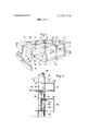
FIG. 3 is a sectional view along line 33 of FIG. 2;
FIG. 4 is a sectional view along line 4-4 of FIG. 3;
FIG. 5 is a sectional view along line 5-5 of FIG. 4;
FIG. 6 is a perspective view of an equipment assembly forming part of an equipped booth;
FIG. 7 is a perspective view of equipped booths arranged side-by-side and viewed from the inside of one booth;
FIG. 8 is a perspective view of a differently equipped booths seen from the inside and FIG. 9 is a perspective view of still differently equipped booths in a sie-by-side arrangement.
DESCRIPTION OF THE EMBODIMENTS Turning now to FIG. 1, there is shown a series ofjuxtaposed equipment booths identified with reference numerals 10 to 24, each having four vertical carrier columns 30. As it will be described in detail later, the outside of each column is formed by carrier sleeves 32 and spacer sleeves 34. To the carrier sleeves 32 there are attached various items of equipment, such as wall panel elements 36, benches 38, counter tops and illuminating bodies 42, the structure of which will be described in detail as the specification progresses. It may be already observed in FIG. 1 that completely equipped office work places may be installed, for example, in the teller room of a bank building without the necessity of performing remodelling work on the building itself.
From the description that follows it will be further seen I posts 50 there are inserted a plurality of carrier sleeves and spacer sleeves as it will be discussed in connection with the structure of one of the columns 30. On the hollow post 50 of the column 30 closest to the observer of FIG. 2 there is arranged, starting from the bottom, a spacer sleeve 34a which supports in series four carrier sleeves 32a-32d, followed by three spacer sleeves 34b-34d, a carrier sleeve 32f for a sign 52, a further spacer sleeve 34c and, finally, a carrier sleeve 32f. To the carrier sleeves 32a-32d there are secured a planar wall panel 54, a counter top 56, an arcuate wall panel 58, a compartment shelf 60, a table top 62, a further arcuate wall panel 64 and a further compartment shelf 66. To mutually corresponding carrier sleeves 32f adjacent columns 30 there are affixed small upper transversal beams which have essentially a U-shaped profile. Their configuration can be clearly seen in FIG. 2. The transversal beams 70 carry, by means of a T- member 72 which is welded to the appropriate transversal beam, the illuminating bodies indicated generally at 42 in FIG. 1. To the transversal beams '70 there are also secured half housing shells 74 which, together with an upper and a lower diffusing plate 76 and 78, respectively, complement each illuminating body 42. The light sources themselves are not shown in the drawings; they may be formed in a desired manner of known ele-' ments such as neon tubes or the like. The illuminating bodies 42 are accessible from above and from below and are therefore adapted to receive, for example, components ofan air conditioning unit.
As it may be observed from FIG. 3, for the securing of the different plates large and small transversal beams 80 and 82 are used if the latter should also serve for connecting two adjacent columns 30 to one another. In such a case the last-named transversal beams are welded to one or more carrier sleeves 32 and carry plates 60, 62 and 66 welded thereto. The wall panels 58 and 64, in turn, are secured to the plates 60, 62 and 66.
In FIGS. 4 and 5 there is shown the inner structure of a column 30. Externally there is disposed a spacer sleeve 34b and a carrier sleeve 340 that surround the hollow support post 50 in which there are disposed electric conductors 100, telephone cables 102, and a dispatch tube 104 containing a cartridge 106. The hollow support post 50 may have at various locations throughgoing insulated electric terminals 10% isolated by a plastic ring a; to these terminals 100b electric conductors, telephone cables and the like may be connected by means of terminals 100d being insulated by a plastic ring 100c in the carrier sleeves, so that desk lamps, telephone and television sets and the like may be coupled to their corresponding cables.
Turning now to FIG. 4, there may be observed a significant feature of a preferred embodiment of the invention. Each sleeve (whether carrier or spacer sleeve) is made of two complemental halves. One sleeve half has two diametrically opposed threaded bores 107, while the other sleeve half is provided with two countersunk bores 108, each in exact axial alignment with a threaded bore 107. In each bore pair 107, 108 there may be inserted a screw (preferably of the type having a hexagonal recessed hole) for tightening the two sleeve halves together and thus clamping the sleeve to the hollow support post 50. In this manner it is possible to remove any selected sleeve from the support post 50 without the necessity of disturbing any other sleeve.
In FIG. 6 there is illustrated the invention apart from its use in connection with a booth assembly. Here, on a hollow support post (not visible in FIG. 6) there are inserted a plurality of concealing sleeves which carry a seat 202 (on a cantilever 200), a typewriter table 204, a desk 206, a phone shelf 208, an office television set 210 and a desk lamp 212 in such a manner that for each item a number of angular positions are possible. In case the hollow support post is cylindrical, the possibilities of angular adjustments are infinite.
FIGS. 7, 8 and 9 do not require additional explanation; the reference numerals provided with a prime sign indicate components which correspond to earlier discussed components, but are of somewhat different configuration. lt may be observed from these three figures that several equipped booths may be arranged in ajuxtaposed relationship in such a manner that at each corner there is provided only a sole column 30 which, in comparison with FIG. 1, is a significant simplification.
It is to be understood that instead of the half housing shells 74 for the illuminating body 42, it is feasible to use at all places an arcuate wall panel similar to the wall panels 36 and 58 discussed earlier.
What is claimed is:
l. Appointments structure particularly for the support of a plurality of items of office equipment, the improvement comprising:
a. a plurality of vertical carrier columns;
b. carrier sleeves disposed in axial series on said carrier columns and surrounding the same, said items being carried by selected ones of said carrier sleeves;
c. spacer sleeves disposed on said carrier columns and surrounding the same, said spacer sleeves being situated adjacent selected carrier sleeves to adjust the height of said items; and
d. at least one transversal beam securing a plurality of said carrier columns to one another in a horizontally spaced relationship to form an appointments unit, said transversal beam being secured to carrier sleeves of the several carrier columns.
2. An improvement as defined in claim 1, wherein each of said vertical carrier columns is configured as a hollow support post including a length of a dispatch tube.
3. An improvement as defined in claim 1, wherein each of said vertical columns is configured as a hollow support post having a cylindrical outer face, and wherein said carrier sleeves are swingable about the axis of their respective hollow support post.
4. An improvement as defined in claim 3, said carrier sleeves including means to fasten them to said hollow support post in any desired angular position.
5. An improvement as defined in claim 1, wherein each of said vertical columns is configured as a hollow support post including conduits disposed therein and outlet terminals connected to said conduits and disposed in the wall of said hollow support post, said outlet terminals being covered by said sleeves and connected to corresponding terminals of said sleeves.
6. An improvement as defined in claim 1, wherein items of equipment are secured to said transversal beam.
7. An improvement as defined in claim 1, wherein at least some of said sleeves are formed of complemental parts including means for securing said parts together.
8. An improvement as defined in claim 1, wherein upper and lower transversal beams are provided for securing a plurality of said carrier columns to one another.
9. An improvement as defined in claim 1, wherein carrier arms for items of equipment are secured to selected ones of said carrier sleeves.
10. An improvement as defined in claim 1, wherein the length of said carrier columns corresponds to the height of a room for said appointments structure.
11. An improvement as defined in claim 8, wherein lighting equipment is secured to at least one of said upper transversal beams.
Claims (11)
1. Appointments structure particularly for the support of a plurality of items of office equipment, the improvement comprising: a. a plurality of vertical carrier columns; b. carrier sleeves disposed in axial series on said carrier columns and surrounding the same, said items being carried by selected ones of said carrier sleeves; c. spacer sleeves disposed on said carrier columns and surrounding the same, said spacer sleeves being situated adjacent selected carrier sleeves to adjust the height of said items; and d. at least one transversal beam securing a plurality of said carrier columns to one another in a horizontally spaced relationship to form an appointments unit, said transversal beam being secured to carrier sleeves of the several carrier columns.
2. An improvement as defined in claim 1, wherein each of said vertical carrier columns is configured as a hollow support post including a length of a dispatch tube.
3. An improvement as defined in claim 1, wherein each of said vertical columns is configured as a hollow support post having a cylindrical outer face, and wherein said carrier sleeves are swingable about the axis of their respective hollow support post.
4. An improvement as defined in claim 3, said carrier sleeves including means to fasten them to said hollow support post in any desired angular position.
5. An improvement as defined in claim 1, wherein each of said vertical columns is configured as a hollow support post including conduits disposed therein and outlet terminals connected to said conduits and disposed in the wall of said hollow support post, said outlet terminals being covered by said sleeves and connected to corresponding terminals of said sleeves.
6. An improvement as defined in claim 1, wherein items of equipment are secured to said transversal beam.
7. An improvement as defined in claim 1, wherein at least some of said sleeves are formed of complemental parts including means for securing said parts together.
8. An improvement as defined in claim 1, wherein upper and lower transversal beams are provided for securing a plurality of said carrier columns to one another.
9. An improvement as defined in claim 1, wherein carrier arms for items of equipment are secured to selected ones of said carrier sleeves.
10. An improvement as defined in claim 1, wherein the length of said carrier columns corresponds to the height of a room for said appointments structure.
11. An improvement as defined in claim 8, wherein lighting equipment is secured to at least one of said upper transversal beams.
Applications Claiming Priority (1)
| Application Number | Priority Date | Filing Date | Title |
|---|---|---|---|
| DE2113111A DE2113111C3 (en) | 1971-03-18 | 1971-03-18 | Furnishing unit with at least one hollow support on which furnishing objects for workplaces can be attached |
Publications (1)
| Publication Number | Publication Date |
|---|---|
| US3786934A true US3786934A (en) | 1974-01-22 |
Family
ID=5801970
Family Applications (1)
| Application Number | Title | Priority Date | Filing Date |
|---|---|---|---|
| US00236098A Expired - Lifetime US3786934A (en) | 1971-03-18 | 1972-03-20 | Carrier structure particularly for office equipment assembly |
Country Status (4)
| Country | Link |
|---|---|
| US (1) | US3786934A (en) |
| DE (1) | DE2113111C3 (en) |
| FR (1) | FR2129744A5 (en) |
| GB (1) | GB1381399A (en) |
Cited By (3)
| Publication number | Priority date | Publication date | Assignee | Title |
|---|---|---|---|---|
| US20020011193A1 (en) * | 1998-10-13 | 2002-01-31 | Beck Robert L. | Work space management and furniture system |
| US6490829B1 (en) | 1988-07-29 | 2002-12-10 | Herman Miller Inc. | Free standing modular architectural beam system |
| US6497075B1 (en) | 1988-07-29 | 2002-12-24 | Herman Miller Inc. | Free standing modular architectural beam system |
Families Citing this family (6)
| Publication number | Priority date | Publication date | Assignee | Title |
|---|---|---|---|---|
| DE3128085C2 (en) * | 1981-07-16 | 1984-07-12 | Planmöbel Eggersmann GmbH & Co KG, 4992 Espelkamp | Free-standing supply column, especially for offices |
| US4569163A (en) * | 1983-07-29 | 1986-02-11 | Long Dennis L | Modular unit adapted for medical use |
| US4637177A (en) * | 1983-07-29 | 1987-01-20 | Long Dennis L | Modular unit adapted for office use |
| FR2558359B1 (en) * | 1983-09-21 | 1988-08-05 | Paturaud Andre | ASSEMBLY FOR THE COMPOSITION OF A SCALABLE STRUCTURE FOR THE CONSTITUTION OF SCAFFOLDING OR COLUMN-SHAPED FURNITURE |
| AU4937396A (en) * | 1995-03-08 | 1996-09-23 | Ludwig Salzinger | Multifunctional table combination |
| DE19539275A1 (en) * | 1995-10-21 | 1997-04-24 | Baumann Hans Dr | Support stand for computer equipment |
Citations (8)
| Publication number | Priority date | Publication date | Assignee | Title |
|---|---|---|---|---|
| US585360A (en) * | 1897-06-29 | Display-rack | ||
| US1408128A (en) * | 1920-05-12 | 1922-02-28 | Will C Neahr | Display stand for incandescent electric lamps |
| US1804912A (en) * | 1929-05-01 | 1931-05-12 | Pie Bakeries Of America Inc | Rack |
| US2136843A (en) * | 1937-04-26 | 1938-11-15 | Andrew J Dinkel | Cabinet |
| US2367082A (en) * | 1942-12-12 | 1945-01-09 | Western Electric Co | Supporting apparatus |
| US2521355A (en) * | 1947-08-20 | 1950-09-05 | Frank P Ford | Combination lamp and display stand |
| GB677263A (en) * | 1949-10-24 | 1952-08-13 | Richard Gent Ltd | Improvements in display brackets and stands |
| US3389882A (en) * | 1966-08-08 | 1968-06-25 | Pfaff & Kendall | Adjustable sign span support |
-
1971
- 1971-03-18 DE DE2113111A patent/DE2113111C3/en not_active Expired
-
1972
- 1972-03-17 FR FR7209374A patent/FR2129744A5/fr not_active Expired
- 1972-03-20 GB GB1293272A patent/GB1381399A/en not_active Expired
- 1972-03-20 US US00236098A patent/US3786934A/en not_active Expired - Lifetime
Patent Citations (8)
| Publication number | Priority date | Publication date | Assignee | Title |
|---|---|---|---|---|
| US585360A (en) * | 1897-06-29 | Display-rack | ||
| US1408128A (en) * | 1920-05-12 | 1922-02-28 | Will C Neahr | Display stand for incandescent electric lamps |
| US1804912A (en) * | 1929-05-01 | 1931-05-12 | Pie Bakeries Of America Inc | Rack |
| US2136843A (en) * | 1937-04-26 | 1938-11-15 | Andrew J Dinkel | Cabinet |
| US2367082A (en) * | 1942-12-12 | 1945-01-09 | Western Electric Co | Supporting apparatus |
| US2521355A (en) * | 1947-08-20 | 1950-09-05 | Frank P Ford | Combination lamp and display stand |
| GB677263A (en) * | 1949-10-24 | 1952-08-13 | Richard Gent Ltd | Improvements in display brackets and stands |
| US3389882A (en) * | 1966-08-08 | 1968-06-25 | Pfaff & Kendall | Adjustable sign span support |
Cited By (4)
| Publication number | Priority date | Publication date | Assignee | Title |
|---|---|---|---|---|
| US6490829B1 (en) | 1988-07-29 | 2002-12-10 | Herman Miller Inc. | Free standing modular architectural beam system |
| US6497075B1 (en) | 1988-07-29 | 2002-12-24 | Herman Miller Inc. | Free standing modular architectural beam system |
| US20020011193A1 (en) * | 1998-10-13 | 2002-01-31 | Beck Robert L. | Work space management and furniture system |
| US7827920B2 (en) | 1998-10-13 | 2010-11-09 | Herman Miller Inc. | Work space management and furniture system |
Also Published As
| Publication number | Publication date |
|---|---|
| DE2113111C3 (en) | 1973-12-06 |
| GB1381399A (en) | 1975-01-22 |
| FR2129744A5 (en) | 1972-10-27 |
| DE2113111A1 (en) | 1972-10-05 |
| DE2113111B2 (en) | 1973-05-17 |
Similar Documents
| Publication | Publication Date | Title |
|---|---|---|
| US3817396A (en) | Portable display apparatus | |
| US3955298A (en) | Poster display frame | |
| US5671852A (en) | Display and decorative fixture apparatus | |
| US3809142A (en) | Multiple height space divider system and connector assembly therefor | |
| US3786934A (en) | Carrier structure particularly for office equipment assembly | |
| CA2238536C (en) | Hybrid office panel construction for a modular office furniture system | |
| US5695261A (en) | Integrally powered modular furniture | |
| US3418765A (en) | Coordinated system for activity isolation | |
| CA1078446A (en) | Bearer structure for furniture | |
| US6497075B1 (en) | Free standing modular architectural beam system | |
| US3828937A (en) | Adjustable pole support system | |
| US3406645A (en) | Prefabricated furniture | |
| US5950371A (en) | Column mountable shelf for furniture systems | |
| US4545168A (en) | Interconnecting wall panels | |
| JP2000505346A (en) | Modular indoor equipment system | |
| US20020023391A1 (en) | Wall and display systems and components | |
| US4117533A (en) | Modular lighting system | |
| US3043642A (en) | Suspended furniture | |
| US20050122665A1 (en) | Shelving | |
| GB2209461A (en) | Modular display system | |
| US3898939A (en) | Shelf assembly | |
| KR102124160B1 (en) | Prefab Double Sided Shelf | |
| JP2785469B2 (en) | Partition unit | |
| CN111713927A (en) | Plant display device for interior decoration | |
| US4959763A (en) | Display frame system |