US3772664A - Incremental tape drive with optically derived control pulses - Google Patents
Incremental tape drive with optically derived control pulses Download PDFInfo
- Publication number
- US3772664A US3772664A US00162083A US3772664DA US3772664A US 3772664 A US3772664 A US 3772664A US 00162083 A US00162083 A US 00162083A US 3772664D A US3772664D A US 3772664DA US 3772664 A US3772664 A US 3772664A
- Authority
- US
- United States
- Prior art keywords
- arrangement
- set forth
- gate
- track
- transport
- Prior art date
- Legal status (The legal status is an assumption and is not a legal conclusion. Google has not performed a legal analysis and makes no representation as to the accuracy of the status listed.)
- Expired - Lifetime
Links
Images

Classifications
-
- G—PHYSICS
- G06—COMPUTING OR CALCULATING; COUNTING
- G06K—GRAPHICAL DATA READING; PRESENTATION OF DATA; RECORD CARRIERS; HANDLING RECORD CARRIERS
- G06K7/00—Methods or arrangements for sensing record carriers, e.g. for reading patterns
- G06K7/01—Details
- G06K7/016—Synchronisation of sensing process
- G06K7/0163—Synchronisation of sensing process by means of additional timing marks on the record-carrier
-
- G—PHYSICS
- G06—COMPUTING OR CALCULATING; COUNTING
- G06K—GRAPHICAL DATA READING; PRESENTATION OF DATA; RECORD CARRIERS; HANDLING RECORD CARRIERS
- G06K13/00—Conveying record carriers from one station to another, e.g. from stack to punching mechanism
- G06K13/18—Conveying record carriers from one station to another, e.g. from stack to punching mechanism the record carrier being longitudinally extended, e.g. punched tape
-
- G—PHYSICS
- G11—INFORMATION STORAGE
- G11B—INFORMATION STORAGE BASED ON RELATIVE MOVEMENT BETWEEN RECORD CARRIER AND TRANSDUCER
- G11B15/00—Driving, starting or stopping record carriers of filamentary or web form; Driving both such record carriers and heads; Guiding such record carriers or containers therefor; Control thereof; Control of operating function
- G11B15/18—Driving; Starting; Stopping; Arrangements for control or regulation thereof
- G11B15/20—Moving record carrier backwards or forwards by finite amounts, i.e. backspacing, forward spacing
-
- G—PHYSICS
- G11—INFORMATION STORAGE
- G11B—INFORMATION STORAGE BASED ON RELATIVE MOVEMENT BETWEEN RECORD CARRIER AND TRANSDUCER
- G11B15/00—Driving, starting or stopping record carriers of filamentary or web form; Driving both such record carriers and heads; Guiding such record carriers or containers therefor; Control thereof; Control of operating function
- G11B15/18—Driving; Starting; Stopping; Arrangements for control or regulation thereof
- G11B15/46—Controlling, regulating, or indicating speed
- G11B15/52—Controlling, regulating, or indicating speed by using signals recorded on, or derived from, record carrier
-
- G—PHYSICS
- G11—INFORMATION STORAGE
- G11B—INFORMATION STORAGE BASED ON RELATIVE MOVEMENT BETWEEN RECORD CARRIER AND TRANSDUCER
- G11B5/00—Recording by magnetisation or demagnetisation of a record carrier; Reproducing by magnetic means; Record carriers therefor
- G11B5/008—Recording on, or reproducing or erasing from, magnetic tapes, sheets, e.g. cards, or wires
Definitions
- ABSTRACT [30] F i A li i P i it D First and second information sequence are stored cha- July 14 1970 Germany P 20 34 8361 racter-interlaced on magnetic tape. Bits representing characters are stored serially, each character occupy- 521 11.8. C1, 340/1741 A 179/100 2 s ing a determined length rack tape [51] Int. Cl. Gllb 151/08 has markings extending the length of each character 58 Field of Search 340/1741 A 174.1 B first infmmafim sequence- Stepwise tramp 340/174 l G 174.] rig/1002s has constant speed driving phase and variable speed 1 starting and braking phase.
- This invention relates to storage arrangements for digital information.
- it relates to such storage arrangements having elongated signal carrier means storing said information in serial form.
- said elongated signal carrier means is transported along a predetermined path by stepwise transport means which have a driving phase of substantially constant velocity.
- the transport means are controlled in such a manner that a selected portion of said elongated signal carrier means assigned to a determined information unit is driven past energized read-write means during the drive or constant velocity phase of the transport means.
- the digital information comprises a plurality of characters, each of the characters comprising a plurality of bits.
- This information is stored on a surface-type storage as for example a mag netic tape.
- the bits constituting such character may be stored in either parallel form in a plurality of tracks of the signal storage means and recorded and read out simultaneously, or they may be stored in serial form in a single track of the storage.
- the serial type of storage finds great application in socalled input-output devices which operate in conjunction with relatively slowly operating equipment as, for example, typewriters.
- the relatively low processing speed of such a serial storage does not constitute a disadvantage, while its operational simplicity constitutes a great advantage in this type of application.
- Such equipment generally comprises transport means which transport the tape step-by-step, each step encompassing a portion of the tape which is sufficiently large for read out or recording of all bits of a character, including any necessary parity bits, at a constant velocity by means of a read-write head.
- the steps of the transport means comprise a starting phase wherein the velocity increases continually, a driving phase wherein the velocity remains constant, and a braking phase of decreasing velocity.
- no read out or recording should occur during the starting or braking phases because of the variation in velocity.Under such conditions, only approximately 50 percent of the track length can actually be utilized for storing purposes. This means that the already-limited storage of such storages due to the overall length limitations of the tape is further decreased.
- each of said characters occupying a determined character length along said first track.
- the elongated signal carrier means further have a second track having a plurality of markings indicative of the beginning and end of each of said characters of said first information sequence.
- Transport means transport said elongated signal carrier means stepwise alng a predetermined path, each of said steps having a driving phase of substantially constant velocity, a starting phase of increasing velocity, and a braking phase of decreasing velocity.
- read-write means in operative proximity to said first track and sensing means for sensing said markings on said second track and furnishing marking signals in response thereto.
- Control circuit means are connected to said sensing means and said transport means for controlling said transport means in response to said markings and in response to a first and second external selection signal, in such a manner that portions of said elongated signal carrier means assigned to said first information sequence are transported past said read-write head at a constant velocity in the presence of a first external selection signal and portions of said elongated signal carrier means assigned to said second information sequence are transported at a constant velocity past said read-write head in the presence of said second external selection signal.
- the markings extend along the character length portions of said elongated signal carrier means assigned to said first information sequence, the spaces between said markings thereby extending alony along portions of signal carrier means assigned to said second information sequence.
- an OR gate which furnishes an output pulse for the duration of the marking signal in the presence of a first selection signal, and in the absence of a marking signal in the presence of a second selection signal.
- the trailing edge of the output pulse of the OR gate is used to initiate the braking phase of the transport means.
- an AND gate which is gated by the output pulse of the above-mentioned OR gate to permit transmission of signals from the read-write means in the presence of said output pulse.
- the length of elongated signal carrier means transported during the starting phase is equal to that transported during the braking phase, while the sum of the so-transported lengths is equal to the length of signal carrier means transported during the driving phase.
- the above-mentioned markings comprise perforations in the tape, each of the perforations being of substantially rectangular shape and having two sides perpendicular to the direction of motion of the tape and two sides parallel to said direction of motion.
- the length in the direction of motion of the tape corresponds to the above-mentioned character length.
- the space between the perforations is also equal to a character length.
- the perforations may be sensed by optical means, the path from a light source to a photosensitive element being completed by said perforations.
- the cylindrical surface of a guide rod controlling the motion of the tape in the vicinity -of a perforation is used to provide a reflection of the light from the source towards the photosensitive element. In this manner, only a narrow strip of light parallel to the lengthwise edge of the perforations is impinged upon the photosensitive element. This causes the marking signal derived from the photosensitive element to have relatively sharp leading and trailing edges.
- the sensing arrangement in the direction of transport of the tape is placed at a small angle relative to the perpendicular to the surface of the tape. This tends to minimize reflections from the tape surface.
- a further advantage from the present invention results if the magnetic tape is housed in a cassette which is brought in operative association with the sensing arrangement and the transport means when inserted into the apparatus containing the storage arrangement of the present invention.
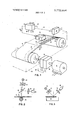
- FIG. 1 shows an arrangement of the present invention in diagrammatic form
- FIG. 2 shows a first embodiment of the sensing arrangement of the present invention
- FIG. 3 shows a further embodiment of the optical sensing arrangement of the present invention
- FIG. 4 is a diagram showing the first and second tracks on the elongated signal carrier means with the first and second information sequence and the markings;
- FIG. 5 is a block diagram of the control circuit of the present invention.
- the elongated signal carrier means illustrated in FIG. 1 are a magnetic tape 11 which has a plurality of parallel tracks 12.
- the tape may be wound back and forth between reels l5 and 16 which are mounted respectively on shafts 13 and 14.
- Transport of the tape in the recording or read out direction is effected by a continuously operating motor 17 which may be connected with shaft 13 carrying reel by means of a controllable magnetic coupling 18 and a controllable magnetic brake 19.
- the re-winding means and the means for maintaining the proper tension in the tape are not shown, since they do not constitute a part of the present invention and are not necessary for the understanding thereof.
- the tape 11 and the reels l5 and 16 are mounted in a changeable cassette whose housing is indicated by the dash-dot line 20. When the cassette is inserted in the equipment containing the storage arrangement of the present invention, the shaft 13 is automatically connected to the drive shaft 22 by means of a conventional claw coupling indicated by dashed lines numbered 21 in FIG. 1.
- Read-write head 25 may comprise a plurality of magnets and is connected to an arrangement 26 indicated by dashed lines but not further illustrated, which is operable to move the head in a direction perpendicular to the surface of the tape and in a direction perpendicular to the tracks, thereby allowing the head to be brought into operative proximity to a selected one of the number of parallel tracks shown on the tape.
- a track 27 on tape 11 has a plurality of optically scannable markings spaced at equal distances from each other which are used to control the tape transport and the read out from head 25.
- the markings are rectangular perforations 28.
- the scanning arrangement is denoted by reference numeral 29 which is arranged over the surface of the guide rod 24.
- the cylindrical surface of guide rod 24 serves as a reflection surface for the scanning light beam.
- a scanning arrangement is shown in FIG. 2.
- a light source 30 generates a light beam which passes through a condensor lens 31 and a semi-transmissive mirror 32, and, in the presence of a perforatlon, impinges upon the upper surface of guide rod 24. Because of the curvature of the reflection surface, a narrow strip of light in the same plane is reflected to the semi-transmissive mirror 32 and is reflected therefrom through objective 33 onto the photosensitive element 34.
- the light strip formed on the surface of photosensitive element 34 by objective 33 is parallel to the lengthwise edge of perforation 28. As a result of this, the edges of perforation 28 cause sharp light to dark transitions in the scanning arrangement 29.
- the direction of propogation of the incident light beam upon the surface is at a small angle a relative to the perpendicular to the surface of the tape. This substantially eliminates any stray reflections frm the upper surface of the tape.
- FIG. 3 shows an alternate embodiment of the scanning arrangement.
- the light beam emanating from the source 30 is impinged upon surface 14 by a condensor lens 31 at a predetermined angle.
- Objective 33 and element 34 are placed in the direction of the reflected beam. All the optical elements lie in a plane determined by the center of the guide rod.
- the digital information in a first and second information sequence to be entered upon the tape or read from the tape comprises a plurality of characters each of the characters comprising a plurality of bits.
- the characters are entered upon the tape in serial form, that is the bits constituting the coding of each character are entered sequentially in the direction of transport of the tape or, in other words, along the track.
- a determined length of tape herein designated as character length, is required for entering of all the bits constituting a character.
- the character length also includes any length required for the inclusion of parity bits and space required for providing the necessary tolerances at the end of each character length. All character lengths along the tape are equal.
- the transport means are stepwise transport means requiring a starting phase of increasing velocity until the proper operating velocity is reached, and a braking phase of decreasing velocity wherein the speed is decreased from the constant operating speed to a stop. Further it is necessary that the character to be read out is transported past the read-write head at a constant speed, that is during the driving phase of the transport meansfThus the markings are separated by spaces which are provided to accommodate the braking phase associated with the previously read out or entered character and the starting phase associated with the next sequential character to be entered or read out. Braking of the transport means is accomplished by means of coupling 18and'brake 19.
- FIG. 4 shows a section ofan information carrying F track in line a and a section of the second track having I the markings inline bpThesections of track 1, shown in line a,--labelled A correspond to the length of track transportedduring starting phase, the portions'of track labeled" B are the portions-containing the characters and'are to be transported past the read-write head duringthe driving phase, while the portions, indicated as C portion labeled B.
- section A and C can each be approximately :5mmlo'ng, while the length in the transport direction of portionB may-be 1 mm.
- the perforations 28 which are located opposite sections Bin line a have edges 35 in the direction of motion of the tape, which edges have thesame length as the portions B in line a. Further, the spaces 36 between adjacent perforations 28 correspond to the combined length of sections C and A in line a of FIG. 4.
- the perforations in track 27 serve to control the recording and read out of information, aswell as the movement of the tape.
- the scanningarrangement 29 furnishes .signalsshown in lines 0 of FIG. 4.
- Leading edge 37 which results from the scanning of the front edge of one "40 via line 39.
- An input to'control-circuit 40 is furnishedvia line: 41 to read-write'head 25 allows signals frornthishead -to' become effective onlyfor sectionsB of track A for w-hich thescanned signal level That is,
- signals from head 25 are transmitted to terminal 59/41 through the control circuit. under the above-described conditionduring read-out.
- Signals are applied at terminal 59/41 andtransmitted to line '41/59 (i.e. to the recording head 25)'under the'same condition (see also-FIG. 5).
- control circuit means 40 yield a signal via line 42 to'coupling 18- and brake 19 which is derived duringthe scanning of the trailing edge of a perfora- .tion, that is during the scanning of an edge 38.
- thebraking phase is initiated, causing the tape to stop at the end of tape portion C.
- a start signal applied to the input of coupling 18'andbrake 19 can cause the band to be transported again. It then enters the starting phase A and,
- Line d of FIG. 4 shows the variation of speed in a highly simplified form. It is noted that portions A of line a correspond to section 43 with increasing velocity,
- portions B of line a correspond to section 44 with substantially constant speed, while sections C of' line a correspond to lines 45 indicating decreasing velocity.
- Point '46 represents the stopped position of the tape, that is the dividing line between portions A and C.
- Track 12 of the tape herein referred to as the first track, also stores a second information sequence.
- the portions of the tape carrying the second information sequence correspond to the same letters designating the portions carrying the first information sequence, but are denoted by a prime. It is seen that the starting and braking phases of the second information sequence coincides with the driving phase of the first information sequence, and vice versa.
- the tape speed for this mode 'of operation is indicated in line e.
- the second information sequence can also be read out by means of perforations 28 in conjunction with scanning means 49 and control circuit means 40.
- FIG. 5 shows the control circuit.
- the signals read out by read-write head 25 are supplied to the'input of the control circuit 40 via line 41.
- An amplifier 47 and pulse shaper 48 furnish standard pulses in response to each bit read out by head25.
- the marking signal that is the signal supplied by the photosensitive element 34, is applied to an amplifier 51 followed by a pulse shaper 52.
- the output signal of pulse shaper 52 is connected to one input of an AND gate 53 whose other input is connected to a line 58 furgate 55 whose first input is connected to a line furnishing the second selection signal.
- the outputs of AND. gates 53 and 55 are connected to two inputs of an OR gae 56 whose output is in turn connected to an input of AND gate 50 via a line 57.
- the output of AND gate 50 furnished at a terminal 59 constitutes the data output. Terminal 59 is herein referred to as the data transmission terminal.
- the arrangement operates as follows: If a selection signal is applied to line 58, AND gate 53 is gated to permit transmission of the marking signals, that is the pulses derived from the output of pulse shaper 52. OR gate 56 than furnishes one input to AND gate 50, allowing any signals (of the first information sequence) read out by read-write head 25 to be transmitted through AND gate 50 to the data transmission terminal 59. In the absence of a marking signal, that is asignal at the output of pulse shaper 52, AND gate 53 is blocked. AND gate 55 is blocked due to the absence of a selection signal on line 60.
- OR gate 56 is also applied to a circuit 61 furnishing an output to a line 42.
- This circuit may for example be a differentiating circuit operative on the trailing edge of the pulse furnished by OR gate 56, the signal on line 42 being used to initiate the braking phase of the transport means, that is the signal on line 42 is applied to coupling 18 and brake 19. It should be noted that a pulse is always present at the output of gate 56 during read out of an information series, regardless of which information series it is. Thus the trailing edge of this pulse always indicates the initiation of the braking phase.
- Digital storage arrangement storing a first and second information sequence, each of said information sequences having a plurality of characters, each of said characters having a plurality of bits, comprising, in combination, elongated signal carrier means having a first track, said first track having said first and second information sequence recorded thereon bit serially and in character-interlaced form, each of said characters occupying a determined character length along said first track, said elongated signal carrier means further having a second track having a plurality of markings indicative of the beginning and end of each of said characters of said first information sequence; transport means for effecting stepwise transport of said elongated signal carrier means along a predetermined path, said transport means having a starting phase of increasing speed, a driving phase of substantially constant speed, and a braking phase of decreasing speed; read-write means positioned in operative proximity to said first track of said elongated signal carrier means; sensing means for sensing said markings on said second track and furnishing marking signals in response thereto; and control circuit means connected to said sensing means and said transport
- control circuit means further comprising means connecting said control circuit means to said read-write means; wherein said control circuit means have a data transmission terminal; and wherein said control circuit means comprise logic circuit means controlled by said external selection signals and said marking signals, for permitting transmission of signals between said data transmission terminal and said read-write means during said driving phase of said transport means, and blocking transmission of signals between said data transmission terminal and said readwrite means during said starting and braking phases of said transport means.
- each of said markings extends a distance along said second track substantially equal to said determined character length, the position of each of said markings along said second track corresponding to the position of a corresponding one of said characters of said first information sequence along said first track.
- said logic circuit means comprise a first AND gate having a first and second input and an output; means connecting said first input to said read-write means; selector switch means connected to said sensing means and furnishing a selector signal at a selector output in the presence or absence of said marking signals under control of said first or second selection signal respectively; and means connecting said second AND gate input to said selector output.
- selector signal is a pulse having a trailing edge; and wherein said control circuit means comprises additional circuit means responsive to said trailing edge of said pulse for initiating said braking phase of said transport means.
- said selector switch means comprise an OR gate having an OR gate output connected to said second input of said first AND gate, and a first and second OR gate input; a second AND gate having an output connected to said first OR gate input, a first input connected to said sensing means and a second input connected to receive said first selector signal; a third AND gate having an output connected to said second OR gate input, a first input connected to receive said second selector signal, and a second input; and inverter means connecting said sensing means to said second input of said third AND gate.
- each of said markings comprises a substantially rectangular perforation.
- sensing means comprise optical sensing means.
- optical sensing means comprise a light source, and a photosensitive element positioned in such a manner relative to said elongated signal carrier means that said perforations provide a path from said light source to said photosensitive element.
- said elongated signal carrier means comprise a magnetic tape; further comprising tape guide rods; and wherein said light path includes reflection from said guide rod.
Landscapes
- Engineering & Computer Science (AREA)
- Physics & Mathematics (AREA)
- General Physics & Mathematics (AREA)
- Theoretical Computer Science (AREA)
- Artificial Intelligence (AREA)
- Computer Vision & Pattern Recognition (AREA)
- Signal Processing For Digital Recording And Reproducing (AREA)
- Recording Or Reproducing By Magnetic Means (AREA)
Abstract
First and second information sequence are stored characterinterlaced on magnetic tape. Bits representing characters are stored serially, each character occupying a determined length of tape. Second track on tape has markings extending the length of each character of first information sequence. Stepwise tape transport has constant speed driving phase and variable speed starting and braking phase. The markings on second track are sensed and control transport means so that the transport drive phase coincides with read out of character from selected one of the two sequences.
Description
United States Patent [191 1111 3,772,664 Schlickeiser Nov. 13, 1973 [54] INCREMENTAL TAPE DRIVE WITH 3,617,651 11/1971 Bell 179/100.2 S
OPTICALLY DERIVED CONTROL PULSES 3,465,128 9/1969 Poumakis et al. 340/ 174.1 A 3,275,208 9/1966 Poumakis et a1. 340/174.1 A Inventor: Klaus Schllckelser, 3,614,757 10/1971 Burr 340/1741 A Weisskreuzstrasse 212, Boll near Hechmgen Germany Primary Examiner-Vincent P. Canney [22] Filed: July 13, 1971 Attorney-Michael S. Striker [21] Appl. No.2 162,083
[57] ABSTRACT [30] F i A li i P i it D First and second information sequence are stored cha- July 14 1970 Germany P 20 34 8361 racter-interlaced on magnetic tape. Bits representing characters are stored serially, each character occupy- 521 11.8. C1, 340/1741 A 179/100 2 s ing a determined length rack tape [51] Int. Cl. Gllb 151/08 has markings extending the length of each character 58 Field of Search 340/1741 A 174.1 B first infmmafim sequence- Stepwise tramp 340/174 l G 174.] rig/1002s has constant speed driving phase and variable speed 1 starting and braking phase. The markings on second [56] References Cited track are sensed and control transport means so that the transport drive phase coincides with read out of UNITED STATES PATENTS character from selected one of the two sequences. 3,631,427 12/1971 Hein et a]. 340/l74.1 A 3,332,084 7/1967 Wahrer 340/1741 A 18 Claims, 5 Drawing Figures 40 54 7 j l l: U
I r i 1 1 5 51 52 1 l 1 l 48 25 g l D 17*, IL
PAIENTED Nov 13 ms SHEET 10F 2 FIG.3
FAIENTEDuuvmszs 3.772.664
SHEET 2 OF 2 INCREMENTAL TAPE DRIVE WITH OPTICALI JY DERIVED CONTROL PULSES BACKGROUND OF THE INVENTION This invention relates to storage arrangements for digital information. In particular, it relates to such storage arrangements having elongated signal carrier means storing said information in serial form. It further relates in particular to storage arrangements wherein said elongated signal carrier means is transported along a predetermined path by stepwise transport means which have a driving phase of substantially constant velocity. The transport means are controlled in such a manner that a selected portion of said elongated signal carrier means assigned to a determined information unit is driven past energized read-write means during the drive or constant velocity phase of the transport means.
In the following discussion the digital information comprises a plurality of characters, each of the characters comprising a plurality of bits. This information is stored on a surface-type storage as for example a mag netic tape. The bits constituting such character may be stored in either parallel form in a plurality of tracks of the signal storage means and recorded and read out simultaneously, or they may be stored in serial form in a single track of the storage. While data processing arrangements in general use the parallel type of storage, the serial type of storage finds great application in socalled input-output devices which operate in conjunction with relatively slowly operating equipment as, for example, typewriters. Thus the relatively low processing speed of such a serial storage does not constitute a disadvantage, while its operational simplicity constitutes a great advantage in this type of application. Such equipment generally comprises transport means which transport the tape step-by-step, each step encompassing a portion of the tape which is sufficiently large for read out or recording of all bits of a character, including any necessary parity bits, at a constant velocity by means of a read-write head. Thus the steps of the transport means comprise a starting phase wherein the velocity increases continually, a driving phase wherein the velocity remains constant, and a braking phase of decreasing velocity. Generally speaking, no read out or recording should occur during the starting or braking phases because of the variation in velocity.Under such conditions, only approximately 50 percent of the track length can actually be utilized for storing purposes. This means that the already-limited storage of such storages due to the overall length limitations of the tape is further decreased.
SUMMARY OF THE INVENTION form, each of said characters occupying a determined character length along said first track. The elongated signal carrier means further have a second track having a plurality of markings indicative of the beginning and end of each of said characters of said first information sequence. Transport means transport said elongated signal carrier means stepwise alng a predetermined path, each of said steps having a driving phase of substantially constant velocity, a starting phase of increasing velocity, and a braking phase of decreasing velocity. Further provided are read-write means in operative proximity to said first track and sensing means for sensing said markings on said second track and furnishing marking signals in response thereto. Control circuit means are connected to said sensing means and said transport means for controlling said transport means in response to said markings and in response to a first and second external selection signal, in such a manner that portions of said elongated signal carrier means assigned to said first information sequence are transported past said read-write head at a constant velocity in the presence of a first external selection signal and portions of said elongated signal carrier means assigned to said second information sequence are transported at a constant velocity past said read-write head in the presence of said second external selection signal.
In a preferred embodiment of the present invention, the markings extend along the character length portions of said elongated signal carrier means assigned to said first information sequence, the spaces between said markings thereby extending alony along portions of signal carrier means assigned to said second information sequence.
In a preferred embodiment of the present invention an OR gate is provided which furnishes an output pulse for the duration of the marking signal in the presence of a first selection signal, and in the absence of a marking signal in the presence of a second selection signal. The trailing edge of the output pulse of the OR gate is used to initiate the braking phase of the transport means. Further provided is an AND gate which is gated by the output pulse of the above-mentioned OR gate to permit transmission of signals from the read-write means in the presence of said output pulse.
In a particularly preferred embodiment of the present invention, the length of elongated signal carrier means transported during the starting phase, is equal to that transported during the braking phase, while the sum of the so-transported lengths is equal to the length of signal carrier means transported during the driving phase.
In a particularly preferred embodiment of the present invention, the above-mentioned markings comprise perforations in the tape, each of the perforations being of substantially rectangular shape and having two sides perpendicular to the direction of motion of the tape and two sides parallel to said direction of motion. The length in the direction of motion of the tape corresponds to the above-mentioned character length. The space between the perforations is also equal to a character length. The perforations may be sensed by optical means, the path from a light source to a photosensitive element being completed by said perforations.
It is particularly advantageous if the cylindrical surface of a guide rod controlling the motion of the tape in the vicinity -of a perforation is used to provide a reflection of the light from the source towards the photosensitive element. In this manner, only a narrow strip of light parallel to the lengthwise edge of the perforations is impinged upon the photosensitive element. This causes the marking signal derived from the photosensitive element to have relatively sharp leading and trailing edges.
It is further advantageous if the sensing arrangement in the direction of transport of the tape is placed at a small angle relative to the perpendicular to the surface of the tape. This tends to minimize reflections from the tape surface.
A further advantage from the present invention results if the magnetic tape is housed in a cassette which is brought in operative association with the sensing arrangement and the transport means when inserted into the apparatus containing the storage arrangement of the present invention.
The novel features which are considered as characteristic for the invention are set forth in particular in the appended claims. The invention itself, however, both as to its construction and its method of operation, together with additional objects and advantages thereof, will be best understood from the following description of specific embodiments when read in connection with the accompanying drawing.
BRIEF DESCRIPTION OF THE DRAWING FIG. 1 shows an arrangement of the present invention in diagrammatic form;
FIG. 2 shows a first embodiment of the sensing arrangement of the present invention;
FIG. 3 shows a further embodiment of the optical sensing arrangement of the present invention;
FIG. 4 is a diagram showing the first and second tracks on the elongated signal carrier means with the first and second information sequence and the markings; and
FIG. 5 is a block diagram of the control circuit of the present invention.
DESCRIPTION OF THE PREFERRED EMBODIMENTS A preferred embodiment of the present invention will now be described with reference to the drawing.
The elongated signal carrier means illustrated in FIG. 1 are a magnetic tape 11 which has a plurality of parallel tracks 12. The tape may be wound back and forth between reels l5 and 16 which are mounted respectively on shafts 13 and 14. Transport of the tape in the recording or read out direction is effected by a continuously operating motor 17 which may be connected with shaft 13 carrying reel by means of a controllable magnetic coupling 18 and a controllable magnetic brake 19. The re-winding means and the means for maintaining the proper tension in the tape, are not shown, since they do not constitute a part of the present invention and are not necessary for the understanding thereof. The tape 11 and the reels l5 and 16 are mounted in a changeable cassette whose housing is indicated by the dash-dot line 20. When the cassette is inserted in the equipment containing the storage arrangement of the present invention, the shaft 13 is automatically connected to the drive shaft 22 by means of a conventional claw coupling indicated by dashed lines numbered 21 in FIG. 1.
In the operating region, that is in the vicinity or readwrite head 25, the tape is maintained in a horizontal plane by means of guide rods 23 and 24. Read-write head 25 may comprise a plurality of magnets and is connected to an arrangement 26 indicated by dashed lines but not further illustrated, which is operable to move the head in a direction perpendicular to the surface of the tape and in a direction perpendicular to the tracks, thereby allowing the head to be brought into operative proximity to a selected one of the number of parallel tracks shown on the tape.
A track 27 on tape 11 has a plurality of optically scannable markings spaced at equal distances from each other which are used to control the tape transport and the read out from head 25. In the example shown, the markings are rectangular perforations 28. The scanning arrangement is denoted by reference numeral 29 which is arranged over the surface of the guide rod 24. The cylindrical surface of guide rod 24 serves as a reflection surface for the scanning light beam.
A scanning arrangement is shown in FIG. 2. A light source 30 generates a light beam which passes through a condensor lens 31 and a semi-transmissive mirror 32, and, in the presence of a perforatlon, impinges upon the upper surface of guide rod 24. Because of the curvature of the reflection surface, a narrow strip of light in the same plane is reflected to the semi-transmissive mirror 32 and is reflected therefrom through objective 33 onto the photosensitive element 34. The light strip formed on the surface of photosensitive element 34 by objective 33 is parallel to the lengthwise edge of perforation 28. As a result of this, the edges of perforation 28 cause sharp light to dark transitions in the scanning arrangement 29. The direction of propogation of the incident light beam upon the surface is at a small angle a relative to the perpendicular to the surface of the tape. This substantially eliminates any stray reflections frm the upper surface of the tape.
FIG. 3 shows an alternate embodiment of the scanning arrangement. In this arrangement, the light beam emanating from the source 30 is impinged upon surface 14 by a condensor lens 31 at a predetermined angle. Objective 33 and element 34 are placed in the direction of the reflected beam. All the optical elements lie in a plane determined by the center of the guide rod.
As stated above, the digital information in a first and second information sequence to be entered upon the tape or read from the tape, comprises a plurality of characters each of the characters comprising a plurality of bits. The characters are entered upon the tape in serial form, that is the bits constituting the coding of each character are entered sequentially in the direction of transport of the tape or, in other words, along the track. Thus a determined length of tape, herein designated as character length, is required for entering of all the bits constituting a character. The character length also includes any length required for the inclusion of parity bits and space required for providing the necessary tolerances at the end of each character length. All character lengths along the tape are equal. It must be further kept in mind that the transport means are stepwise transport means requiring a starting phase of increasing velocity until the proper operating velocity is reached, and a braking phase of decreasing velocity wherein the speed is decreased from the constant operating speed to a stop. Further it is necessary that the character to be read out is transported past the read-write head at a constant speed, that is during the driving phase of the transport meansfThus the markings are separated by spaces which are provided to accommodate the braking phase associated with the previously read out or entered character and the starting phase associated with the next sequential character to be entered or read out. Braking of the transport means is accomplished by means of coupling 18and'brake 19.
FIG. 4 shows a section ofan information carrying F track in line a and a section of the second track having I the markings inline bpThesections of track 1, shown in line a,--labelled A correspond to the length of track transportedduring starting phase, the portions'of track labeled" B are the portions-containing the characters and'are to be transported past the read-write head duringthe driving phase, while the portions, indicated as C portion labeled B. For example, section A and C can each be approximately :5mmlo'ng, while the length in the transport direction of portionB may-be 1 mm.
As shown in line b of FIG. 4, the perforations 28 which are located opposite sections Bin line a have edges 35 in the direction of motion of the tape, which edges have thesame length as the portions B in line a. Further, the spaces 36 between adjacent perforations 28 correspond to the combined length of sections C and A in line a of FIG. 4.
'As mentioned above, the perforations in track 27 serve to control the recording and read out of information, aswell as the movement of the tape. By scanning perforations 28, the scanningarrangement 29 furnishes .signalsshown in lines 0 of FIG. 4. Leading edge 37, which results from the scanning of the front edge of one "40 via line 39. An input to'control-circuit 40 is furnishedvia line: 41 to read-write'head 25 allows signals frornthishead -to' become effective onlyfor sectionsB of track A for w-hich thescanned signal level That is,
signals from head 25 are transmitted to terminal 59/41 through the control circuit. under the above-described conditionduring read-out. Duringrecording, Signals are applied at terminal 59/41 andtransmitted to line '41/59 (i.e. to the recording head 25)'under the'same condition (see also-FIG. 5). isa 1 level.If the scanning arrangement 29 is properly spaced in relation to readwrite head 25, that is if-either the read-write head is on the same line "perpendicular to the direction of the tracks-as scanning arrangement 29, or, alternatively, the read-writehead is placed an integral multiple of 55 perforations away from scanning arrangement 29 in lengthwisedirection of the tapegthen the region B will be scanned simultaneously withthe sensing of a perforationpthat is-when themarking signal is a level 1 signal. Further, control circuit means 40 yield a signal via line 42 to'coupling 18- and brake 19 which is derived duringthe scanning of the trailing edge of a perfora- .tion, that is during the scanning of an edge 38. Thus, at
theend of eachcharacter length B, thebraking phase is initiated, causing the tape to stop at the end of tape portion C. A start signal applied to the input of coupling 18'andbrake 19 can cause the band to be transported again. It then enters the starting phase A and,
upon reaching the subsequent leading edge of the next perforation 28, again reaches its maximum driving spedd..Line d of FIG. 4 shows the variation of speed in a highly simplified form. It is noted that portions A of line a correspond to section 43 with increasing velocity,
portions B of line a correspond to section 44 with substantially constant speed, while sections C of' line a correspond to lines 45 indicating decreasing velocity. Point '46 represents the stopped position of the tape, that is the dividing line between portions A and C.
The starting and braking velocities, 45' and 43, re-
spectively, coincide with the driving phase 44, while the driving phase 44' coincides with the braking and starting phase 45 and 43. The second information sequence can also be read out by means of perforations 28 in conjunction with scanning means 49 and control circuit means 40.
FIG. 5 shows the control circuit. The signals read out by read-write head 25 are supplied to the'input of the control circuit 40 via line 41. An amplifier 47 and pulse shaper 48 furnish standard pulses in response to each bit read out by head25.
The marking signal, that is the signal supplied by the photosensitive element 34, is applied to an amplifier 51 followed by a pulse shaper 52. The output signal of pulse shaper 52 is connected to one input of an AND gate 53 whose other input is connected to a line 58 furgate 55 whose first input is connected to a line furnishing the second selection signal. The outputs of AND. gates 53 and 55 are connected to two inputs of an OR gae 56 whose output is in turn connected to an input of AND gate 50 via a line 57. Inverter 54, AND gates 53 and 55, and OR gate 56, together constitute selector switch means. The output of AND gate 50 furnished at a terminal 59 constitutes the data output. Terminal 59 is herein referred to as the data transmission terminal.
The arrangement operates as follows: If a selection signal is applied to line 58, AND gate 53 is gated to permit transmission of the marking signals, that is the pulses derived from the output of pulse shaper 52. OR gate 56 than furnishes one input to AND gate 50, allowing any signals (of the first information sequence) read out by read-write head 25 to be transmitted through AND gate 50 to the data transmission terminal 59. In the absence of a marking signal, that is asignal at the output of pulse shaper 52, AND gate 53 is blocked. AND gate 55 is blocked due to the absence of a selection signal on line 60. Therefore, no output can result from OR gate 56 and AND gate 50 is blocked, causing signals read out by read-write head 25 from the second information sequence to be blocked from the data transmission terminaLIn the presence of a selection signal on line 60, AND gate 55 becomes transmissive allowing inverted marking signals furnished by inverter 54 to pass through AND gate 55 and then through OR gate 56, thus allowing passage of signals read from read-write head 25 in the absence of a marking signal. These signals of course are the signals associated with the second information sequence. In both cases, the signals are read from read-write head 25, while the transport means are in the driving (constant velocity) phase.
The output of OR gate 56 is also applied to a circuit 61 furnishing an output to a line 42. This circuit may for example be a differentiating circuit operative on the trailing edge of the pulse furnished by OR gate 56, the signal on line 42 being used to initiate the braking phase of the transport means, that is the signal on line 42 is applied to coupling 18 and brake 19. It should be noted that a pulse is always present at the output of gate 56 during read out of an information series, regardless of which information series it is. Thus the trailing edge of this pulse always indicates the initiation of the braking phase.
While the invention has been illustrated and described as embodied in particular sensing, control and transport arrangements, it is not intended to be limited to the details shown, since various modifications, structural and circuit changes may be made without departing in any way from the spirit of the present invention.
Without further analysis, the foregoing will so fully reveal the gist of the present invention that others can by applying current knowledge readily adapt it for various applications without omitting features that, from the standpoint of prior art, fairly constitute essential characteristics of the generic or specific aspects of this invention and, therefore, such adaptations should and are intended to be comprehended within the meaning and range of equivalence of the following claims.
What is claimed as new and desired to be protected by Letters Patent is:
1. Digital storage arrangement storing a first and second information sequence, each of said information sequences having a plurality of characters, each of said characters having a plurality of bits, comprising, in combination, elongated signal carrier means having a first track, said first track having said first and second information sequence recorded thereon bit serially and in character-interlaced form, each of said characters occupying a determined character length along said first track, said elongated signal carrier means further having a second track having a plurality of markings indicative of the beginning and end of each of said characters of said first information sequence; transport means for effecting stepwise transport of said elongated signal carrier means along a predetermined path, said transport means having a starting phase of increasing speed, a driving phase of substantially constant speed, and a braking phase of decreasing speed; read-write means positioned in operative proximity to said first track of said elongated signal carrier means; sensing means for sensing said markings on said second track and furnishing marking signals in response thereto; and control circuit means connected to said sensing means and said transport means for controlling said transport means in dependence upon said marking signals and a first and second externally furnished selection signal, in such a manner that said transport means is in said driving phase when portions of said elongated signal carrier means assigned to said first information sequence pass in operative vicinity of said read-write means in the presence of sad first selection signal, and that said transport means is in said driving phase when portions of said elongated signal carrier means assigned to said second information sequence pass said read-write means in the presence of said second selection signal.
2. An arrangement as set forth in claim 1 further comprising means connecting said control circuit means to said read-write means; wherein said control circuit means have a data transmission terminal; and wherein said control circuit means comprise logic circuit means controlled by said external selection signals and said marking signals, for permitting transmission of signals between said data transmission terminal and said read-write means during said driving phase of said transport means, and blocking transmission of signals between said data transmission terminal and said readwrite means during said starting and braking phases of said transport means.
3. An arrangement as set forth in claim 2, wherein each of said markings extends a distance along said second track substantially equal to said determined character length, the position of each of said markings along said second track corresponding to the position of a corresponding one of said characters of said first information sequence along said first track.
4. An arrangement as set forth in claim 3, wherein the distance between said sequential ones of said markings is substantially equal to said determined character length.
5. An arrangement as set forth in claim 4, wherein the distance traveled by a given point on said elongated signal carrier means along said predetermined path during said driving phase is substantially equal to the sum of the distances traveled by said point during said starting plase and said braking phase.
6. An arrangement as set forth in claim 5, wherein said logic circuit means comprise a first AND gate having a first and second input and an output; means connecting said first input to said read-write means; selector switch means connected to said sensing means and furnishing a selector signal at a selector output in the presence or absence of said marking signals under control of said first or second selection signal respectively; and means connecting said second AND gate input to said selector output.
7. An arrangement as set forth in claim 6, wherein said selector signal is a pulse having a trailing edge; and wherein said control circuit means comprises additional circuit means responsive to said trailing edge of said pulse for initiating said braking phase of said transport means.
8. An arrangement as set forth in claim 7, wherein said additional circuit means comprise a differentiating circuit.
9. An arrangement as set forth in claim 5, wherein the distance traveled by said point along said predetermined path during said braking phase is substantially equal to the distance traveled by said point during said starting phase.
10. An arrangement as set forth in claim 7, wherein said selector switch means comprise an OR gate having an OR gate output connected to said second input of said first AND gate, and a first and second OR gate input; a second AND gate having an output connected to said first OR gate input, a first input connected to said sensing means and a second input connected to receive said first selector signal; a third AND gate having an output connected to said second OR gate input, a first input connected to receive said second selector signal, and a second input; and inverter means connecting said sensing means to said second input of said third AND gate.
11. An arrangement as set forth in claim 10, further comprising pulse shaping means connected to the output of said sensing means.
12. An arrangement as set forth in claim 11, further comprising additional pulse shaping means connected to theoutput of said read-write means.
13. An arrangement as set forth in claim 4, wherein each of said markings comprises a substantially rectangular perforation.
14. An arrangement as set forth in claim 13, wherein said sensing means comprise optical sensing means.
15. An arrangement as set forth in claim 14, wherein said optical sensing means comprise a light source, and a photosensitive element positioned in such a manner relative to said elongated signal carrier means that said perforations provide a path from said light source to said photosensitive element.
16. An arrangement as set forth in claim 15, wherein said elongated signal carrier means comprise a magnetic tape; further comprising tape guide rods; and wherein said light path includes reflection from said guide rod.
17. An arrangement as set forth in claim 16, wherein said path of said light is at a small predetermined angle to a line perpendicular to the direction of transport of said tape.
18. An arrangement as set forth in claim 17, wherein said magnetic tape is housed in a cassette.
Claims (18)
1. Digital storage arrangement storing a first and second information sequence, each of said information sequences having a plurality of characters, each of said characters having a plurality of bits, comprising, in combination, elongated signal carrier means having a first track, said first track having said first and second information sequence recorded thereon bit serially and in character-interlaced form, each of said characters occupying a determined character length along said first track, said elongated signal carrier means further having a second track having a plurality of markings indicative of the beginning and end of each of said characters of said first information sequence; transport means for effecting stepwise transport of said elongated signal carrier means along a predetermined path, said transport means having a starting phase of increasing speed, a driving phase of substantially constant speed, and a braking phase of decreasing speed; read-write means positioned in operative proximity to said first track of said elongated signal carrier means; sensing means for sensing said markings on said second track and furnishing marking signals in response thereto; and control circuit means connected to said sensing means and said transport means for controlling said transport means in dependence upon said marking signals and a first and second externally furnished selection signal, in such a manner that said transport means is in said driving phase when portions of said elongated signal carrier means assigned to said first information sequence pass in operative vicinity of said read-write means in the presence of sad first selection signal, and that said transport means is in said driving phase when portions of said elongated signal carrier means assigned to said second information sequence pass said read-write means in the presence of said second selection signal.
2. An arrangement as set forth in claim 1 further comprising means connecting said control circuit means to said read-write means; wherein said control circuit means have a data transmission terminal; and wherein said control circuit means comprise logic circuit means controlled by said external selection signals and said marking signals, for permitting transmission of signals between said data transmission terminal and said read-write means during said driving phase of said transport means, and blocking transmission of signals between said data transmission terminal and said read-write means during said starting and braking phases of said transport means.
3. An arrangement as set forth in claim 2, wherein each of said markings extends a distance along said second track substantially equal to said determined character length, the position of each of said markings along said second track corresponding to the position of a corresponding one of said characters of said first information sequence along said first track.
4. An arrangement as set forth in claim 3, wherein the distance between said sequential ones of said markings is substantially equal to said determined character length.
5. An arrangement as set forth in claim 4, wherein the distance traveled by a given point on said elongated signal carrier means along said predetermined path during said driving phase is substantially equal to the sum of the distances traveled by said point during said starting plase and said braking phase.
6. An arrangement as set forth in claim 5, wherein said logic circuit means comprise a first AND gate having a first and second input and an output; means connecting said first input to said read-write means; selector switch means connected to said sensing means and furnishing a selector signal at a selector output in the presence or absence of said marking signals under control of said first or second selEction signal respectively; and means connecting said second AND gate input to said selector output.
7. An arrangement as set forth in claim 6, wherein said selector signal is a pulse having a trailing edge; and wherein said control circuit means comprises additional circuit means responsive to said trailing edge of said pulse for initiating said braking phase of said transport means.
8. An arrangement as set forth in claim 7, wherein said additional circuit means comprise a differentiating circuit.
9. An arrangement as set forth in claim 5, wherein the distance traveled by said point along said predetermined path during said braking phase is substantially equal to the distance traveled by said point during said starting phase.
10. An arrangement as set forth in claim 7, wherein said selector switch means comprise an OR gate having an OR gate output connected to said second input of said first AND gate, and a first and second OR gate input; a second AND gate having an output connected to said first OR gate input, a first input connected to said sensing means and a second input connected to receive said first selector signal; a third AND gate having an output connected to said second OR gate input, a first input connected to receive said second selector signal, and a second input; and inverter means connecting said sensing means to said second input of said third AND gate.
11. An arrangement as set forth in claim 10, further comprising pulse shaping means connected to the output of said sensing means.
12. An arrangement as set forth in claim 11, further comprising additional pulse shaping means connected to the output of said read-write means.
13. An arrangement as set forth in claim 4, wherein each of said markings comprises a substantially rectangular perforation.
14. An arrangement as set forth in claim 13, wherein said sensing means comprise optical sensing means.
15. An arrangement as set forth in claim 14, wherein said optical sensing means comprise a light source, and a photosensitive element positioned in such a manner relative to said elongated signal carrier means that said perforations provide a path from said light source to said photosensitive element.
16. An arrangement as set forth in claim 15, wherein said elongated signal carrier means comprise a magnetic tape; further comprising tape guide rods; and wherein said light path includes reflection from said guide rod.
17. An arrangement as set forth in claim 16, wherein said path of said light is at a small predetermined angle to a line perpendicular to the direction of transport of said tape.
18. An arrangement as set forth in claim 17, wherein said magnetic tape is housed in a cassette.
Applications Claiming Priority (1)
| Application Number | Priority Date | Filing Date | Title |
|---|---|---|---|
| DE19702034836 DE2034836A1 (en) | 1970-07-14 | 1970-07-14 | Storage arrangement for digital information |
Publications (1)
| Publication Number | Publication Date |
|---|---|
| US3772664A true US3772664A (en) | 1973-11-13 |
Family
ID=5776703
Family Applications (1)
| Application Number | Title | Priority Date | Filing Date |
|---|---|---|---|
| US00162083A Expired - Lifetime US3772664A (en) | 1970-07-14 | 1971-07-13 | Incremental tape drive with optically derived control pulses |
Country Status (7)
| Country | Link |
|---|---|
| US (1) | US3772664A (en) |
| CH (1) | CH530692A (en) |
| DE (1) | DE2034836A1 (en) |
| FR (1) | FR2101664A5 (en) |
| GB (1) | GB1368441A (en) |
| NL (1) | NL147557B (en) |
| SE (1) | SE377506B (en) |
Cited By (2)
| Publication number | Priority date | Publication date | Assignee | Title |
|---|---|---|---|---|
| US4025957A (en) * | 1974-10-15 | 1977-05-24 | Kokusai Denshin Denwa Kabushiki Kaisha | Magnetic recording system using magnetic tape |
| US4373171A (en) * | 1978-09-21 | 1983-02-08 | Siemens Aktiengesellschaft | Method for decreasing the stop distance in moving tape devices |
Citations (6)
| Publication number | Priority date | Publication date | Assignee | Title |
|---|---|---|---|---|
| US3275208A (en) * | 1964-09-14 | 1966-09-27 | Potter Instrument Co Inc | Incremental tape drive system |
| US3332084A (en) * | 1963-01-07 | 1967-07-18 | Cook Electric Co | Incrementally driven recording apparatus |
| US3465128A (en) * | 1964-09-21 | 1969-09-02 | Potter Instrument Co Inc | Readout system in incremental tape transport |
| US3614757A (en) * | 1961-06-28 | 1971-10-19 | Photocircuits Corp | Displacing apparatus |
| US3617651A (en) * | 1969-08-05 | 1971-11-02 | Beltronix Systems Inc | Device for recording on cardboard and like magnetic record media |
| US3631427A (en) * | 1969-12-30 | 1971-12-28 | Teletype Corp | Incremental tape drive controlled by prerecorded clock track |
-
1970
- 1970-07-14 DE DE19702034836 patent/DE2034836A1/en active Pending
-
1971
- 1971-07-05 NL NL717109231A patent/NL147557B/en unknown
- 1971-07-12 SE SE7109011A patent/SE377506B/xx unknown
- 1971-07-12 CH CH1021871A patent/CH530692A/en not_active IP Right Cessation
- 1971-07-13 US US00162083A patent/US3772664A/en not_active Expired - Lifetime
- 1971-07-13 FR FR7125691A patent/FR2101664A5/fr not_active Expired
- 1971-07-14 GB GB3295071A patent/GB1368441A/en not_active Expired
Patent Citations (6)
| Publication number | Priority date | Publication date | Assignee | Title |
|---|---|---|---|---|
| US3614757A (en) * | 1961-06-28 | 1971-10-19 | Photocircuits Corp | Displacing apparatus |
| US3332084A (en) * | 1963-01-07 | 1967-07-18 | Cook Electric Co | Incrementally driven recording apparatus |
| US3275208A (en) * | 1964-09-14 | 1966-09-27 | Potter Instrument Co Inc | Incremental tape drive system |
| US3465128A (en) * | 1964-09-21 | 1969-09-02 | Potter Instrument Co Inc | Readout system in incremental tape transport |
| US3617651A (en) * | 1969-08-05 | 1971-11-02 | Beltronix Systems Inc | Device for recording on cardboard and like magnetic record media |
| US3631427A (en) * | 1969-12-30 | 1971-12-28 | Teletype Corp | Incremental tape drive controlled by prerecorded clock track |
Cited By (2)
| Publication number | Priority date | Publication date | Assignee | Title |
|---|---|---|---|---|
| US4025957A (en) * | 1974-10-15 | 1977-05-24 | Kokusai Denshin Denwa Kabushiki Kaisha | Magnetic recording system using magnetic tape |
| US4373171A (en) * | 1978-09-21 | 1983-02-08 | Siemens Aktiengesellschaft | Method for decreasing the stop distance in moving tape devices |
Also Published As
| Publication number | Publication date |
|---|---|
| CH530692A (en) | 1972-11-15 |
| NL147557B (en) | 1975-10-15 |
| DE2034836A1 (en) | 1972-01-20 |
| NL7109231A (en) | 1972-01-18 |
| GB1368441A (en) | 1974-09-25 |
| SE377506B (en) | 1975-07-07 |
| FR2101664A5 (en) | 1972-03-31 |
Similar Documents
| Publication | Publication Date | Title |
|---|---|---|
| US3615155A (en) | Recording tape cartridge | |
| US4321635A (en) | Apparatus for selective retrieval of information streams or items | |
| US2683568A (en) | Message selector for magnetic reproducers | |
| US3812532A (en) | Random access memory with tape return to a midtape reference position after reading | |
| US2952010A (en) | Magnetic recording and reproducing system | |
| US3818500A (en) | Card transducing apparatus & method | |
| US5177645A (en) | Method and apparatus for generating, storing, reproducing, and displaying image information | |
| US3986208A (en) | Data recording with high speed search capability | |
| US3772664A (en) | Incremental tape drive with optically derived control pulses | |
| US3895394A (en) | Method for recording and read-out of a plurality of information sequences stored in a single track of a digital storage | |
| GB1397416A (en) | Apparatus for automatically finding microdocuments on a film | |
| US4346290A (en) | Device for the recognition and progressive cancellation of information recorded on a magnetic support | |
| US3869715A (en) | Digital storage having a plurality of information sequences in a single track | |
| US3530447A (en) | Transducer positioning indexer in magnetic disc recorder | |
| US3631427A (en) | Incremental tape drive controlled by prerecorded clock track | |
| US5491591A (en) | Series of images reproduced from addressable storage | |
| US3533071A (en) | Data transfer system and method | |
| US1802595A (en) | Automatic photographic sound-reproducing mechanism | |
| US4448503A (en) | Automatic high speed microfilm searching system | |
| US3641504A (en) | Apparatus for transporting a recording medium for storing information | |
| US3167777A (en) | Recording and reproducing system | |
| US4231070A (en) | High speed copying means and method | |
| US3426336A (en) | Write synchronizing system in incremental tape transport | |
| US3614020A (en) | Tape rewind speed change system | |
| GB1077524A (en) | Recording sound on cinematograph film |