US3772623A - Electromagnetic actuator assembly - Google Patents
Electromagnetic actuator assembly Download PDFInfo
- Publication number
- US3772623A US3772623A US00198202A US3772623DA US3772623A US 3772623 A US3772623 A US 3772623A US 00198202 A US00198202 A US 00198202A US 3772623D A US3772623D A US 3772623DA US 3772623 A US3772623 A US 3772623A
- Authority
- US
- United States
- Prior art keywords
- armature
- pole
- pole piece
- path
- energized
- Prior art date
- Legal status (The legal status is an assumption and is not a legal conclusion. Google has not performed a legal analysis and makes no representation as to the accuracy of the status listed.)
- Expired - Lifetime
Links
- 230000004907 flux Effects 0.000 claims description 13
- 230000009471 action Effects 0.000 claims description 5
- 238000013459 approach Methods 0.000 claims description 5
- 230000004044 response Effects 0.000 claims description 5
- 230000000694 effects Effects 0.000 claims description 4
- 230000006698 induction Effects 0.000 claims description 4
- 230000002596 correlated effect Effects 0.000 claims description 2
- 230000001939 inductive effect Effects 0.000 claims description 2
- 230000007246 mechanism Effects 0.000 description 8
- 230000010355 oscillation Effects 0.000 description 6
- 230000001965 increasing effect Effects 0.000 description 4
- 230000007423 decrease Effects 0.000 description 3
- 230000008901 benefit Effects 0.000 description 2
- 230000000903 blocking effect Effects 0.000 description 2
- 230000000994 depressogenic effect Effects 0.000 description 2
- 238000010276 construction Methods 0.000 description 1
- 230000001276 controlling effect Effects 0.000 description 1
- 230000000875 corresponding effect Effects 0.000 description 1
- 230000001627 detrimental effect Effects 0.000 description 1
- 238000006073 displacement reaction Methods 0.000 description 1
- 230000005484 gravity Effects 0.000 description 1
- 230000002452 interceptive effect Effects 0.000 description 1
- 229920000136 polysorbate Polymers 0.000 description 1
- 230000008707 rearrangement Effects 0.000 description 1
- 230000009131 signaling function Effects 0.000 description 1
- 238000006467 substitution reaction Methods 0.000 description 1
- 238000004804 winding Methods 0.000 description 1
Images
Classifications
-
- H—ELECTRICITY
- H01—ELECTRIC ELEMENTS
- H01F—MAGNETS; INDUCTANCES; TRANSFORMERS; SELECTION OF MATERIALS FOR THEIR MAGNETIC PROPERTIES
- H01F7/00—Magnets
- H01F7/06—Electromagnets; Actuators including electromagnets
- H01F7/08—Electromagnets; Actuators including electromagnets with armatures
- H01F7/14—Pivoting armatures
Definitions
- ABSTRACT A rotary solenoid has a movably mounted pole member which is positioned adjacent to the path of a rotatably mounted armature of the solenoid.
- the pole member is normally spring biased away from the path of the armature.
- the armature moves, when energized, from its normal de-energized position toward the pole member along its rotary path past the pole member.
- the magnetic forces between the pole member and the armature overcome the normal spring bias of the pole member.
- the pole member moves toward the armature to engage the armature and to arrest its motion.
- This invention relates to electromagnetic actuators and, particularly, to precise positioning of a solenoid with a rotatably mountedarmature that swings from a de-energized to an energized position.
- the armature of a known type of rotary solenoid pivots into an energized position opposite a pole piece which is located adjacent to and virtually parallel to the path of movement of the armature of the solenoid.
- an air gap between the armature and the opposing pole face remains substantially constant as the armature swings from a de-energized to an energized position in response to an induced magnetic flux field in the core structure of the solenoid.
- the induced magnetic flux field through the armature and the opposing pole piece initially has a radial and an angular component when the armature is in its de-energized position.
- An additional object of the invention is to predetermine the magnitude of a magnetic flux force across a gap between the pole piece and the armature of a rotary solenoid, such that a braking force will be applied to the moving armature to arrest the motion of the armature at a predetermined position.
- a system of controlling the movement of an electromagnetic actuator includes energizing an armature of the actuator to move the armature along a predetermined path.
- a magnetic stop member is attracted from a spaced position into physical contact with the armature to arrest the motion of the armature at the desired point.
- the stop member is a magnetic pole piece having a periphery congruent with thatof the armature, mounted for movement into contact with the moving armature to arrest the motion of the armature at the desired position.
- a rotary solenoid armature moves toward a matingly contoured pole piece which normally is resiliently biased to an open position spaced from the path of movement of the armature, to
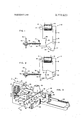
- FIG. 1 shows a rotary solenoid in accordance with one embodiment of the invention, having an armature biased to a deenergized position;
- FIG. 2 shows the solenoid in an energized position
- FIG. 3 shows a keyboard lock mechanism operated by an actuator incorporating the invention.
- an electromagnetic actuator designated generally'by the numeral 10. Its base structure or magnetically permeable core 12, which includes legs 14 and 16, conveniently supports an induction coil 18 which is mounted around the leg 14 of the core 12.
- Leg 16 has at its extremity a junction point 20 for pivotally joining an armature 22 to the core 12.
- the juncture of the armature 22 with the core 12 permits the armature to rotate through at least a portion of a full circular are about the junction or pivot point 20.
- the shape of the armature 22 may vary. However, certain features are advantageously used in the preferred embodiment of the invention even though they are not necessary to practice the invention.
- the armature 22 preferably is substantially in the shape of a circular sector whose center is at the junction point 20. The whole length of the arcuate periphery of the armature 22 constitutes a pole surface 24.
- pole face 24 a lateral displacement of the pole surface 24, also referred to as pole face 24.
- the leg 14 has at its extremity a junction point 26 for movably joining a pole piece, or magnetic stop member 28 to the base structure 12.
- FIG. 1 shows the junction point 26 to be a typical pin and bearing pivot point similar to the junction point 20 joining the armature 22 to the leg 16. It should be understood, however, that the pin and bearing joint at the junction point 26 is shown for illustrative purposes only.
- Other mechanisms for movably attaching the pole piece 28 to the leg 14 of the base structure 12 will serve equally well, as for instance a flexural joint between the base structure 12 and the pole member 28. In selecting the design of a particular joint, however, it should be kept in mind that the actuator will operate most efficiently when the magnetic reluctance of the joints between the various magnetic flux conducting members 12, 22 and 28 is minimal.
- the pole piece 28 has a curved pole surface 30 located parallel to the arcuate path of the pole surface 24 on the armature 22.
- the pole surface 30 is an arcuate concave surface congruent to the armature surface 24.
- the pin 32 is so positioned that a predetermined gap 33 exists between the pole surface 30 and the pole face 24 when the pole member 28 is in contact with the stop 32 and the armature 22 has pivoted to position pole surface 24 opposite pole surface 30 (FIG. 2).
- FIG. 1 shows the spring 34 attached to an aperture 36, through the member 28, and to an adjustable, threaded support 38 which is mounted through a fixed frame, a portion of which is designated by numeral 40. Threaded members 42-42 permit an adjustment in the axial position of the support 38 with respect to the frame 40.
- the arrangement of the support 38 and the capability of the threaded members 42 to adjust the axial position of the support 38 permit an adjustment in the tension force of spring 34.
- By adjusting the tension force of the spring 34 it becomes possible to predetennine the amount of force opposing the spring force which is required to move the member 28 out of contact with the pin 32.
- tension spring 34 While the arrangement of the tension spring 34 is convenient, other known means for urging pole member 28 against stop 32 could be employed within the scope of this invention.
- an adjustable torsion spring (not shown) about the junction point 26 is capable of producing a result similar to that of the mechanism shown in FIG. 1.
- an urging force similar to that produced'by the spring 34, can be obtained by pretensioning the flexural junction in the direction of the fixed stop 32. This type of construction, however, limits the adjustment of the force biasing the member 28 against the stop 32, and the selection of the pretensioning force.
- FIG. 1 shows the actuator 10in an unoperated condition with the armature 22 in a de-energized position.
- the pole surface 24 on the armature is pointed downward due to, for example, a normal gravitational force.
- a spring or a link may be attached to the armature 22 in any convenient manner to normally retain the armature in the deenergized position.
- induction coil 18 Upon actuation of the, induction coil 18, by connecting the coil to an electric circuit (not shown) to produce a current flow through the windings of the coil 18, a magnetic flux field is induced in the core structure 12.
- the path of the flux field extends through leg 16 of the core structure 12, through armature 22, across the space or gap between armature 22 and pole piece 28, and through pole piece 28 back to leg 14 of the core structure 12.
- a force couple is set up in the armature 22 to move the armature in the direction of arrow 44.
- This rotational movement laterally displaces the pole surface 24 on the armature 22 toward a position opposite the pole surface 30 on pole piece 28.
- the armature reaches its fully energized position when the pole surface 24 is substantially opposite and adjacent to the pole surface 30 as shown in FIG. 2.
- the magnetic forces normal to the force in the direction of the arrow 44 come into play just prior to the time when the armature 22 reaches its energized position, to eliminate oscillation of the armature about the energized position.
- the rotational torque couple decreases in magnitude.
- the magnetic force normal thereto increases in magnitude.
- the magnetic force which is directed normally to the pole surfaces 24 and 30 overcomes the urging force of the spring 34 to advance the pole member 28 away from the stop 32 and into the path of the armature 22. Consequently, the pole surface 30 on pole member 28 moves into intimate, frictional contact with the pole surface 24 on the armature 22 to arrest the motion of the armature when it is in its energized position.
- FIG. 2 shows armature 22' in its energized position and further shows pole surfaces 24 and 30 in frictional engagement with each other. Because the gap 33 between the two pole surfaces 24 and. 30 is eliminated, the holding strength of the armature 22v of the actuator is greatly increased over the holding strength of armatures in prior art devices.
- the holdingstrength of an actuator incorporating the present invention is increased for two main reasons. First, the magnetic. flux circuit through the functional members 12, 22 and 28 operates more efficiently dueto the elmination of the gap 33 between the pole surfaces 24 and and. second, the pole surface 30 is in frictional contact with the surface 24 on the armature 22, resisting further movement of the armature as long as the. frictional contact between the pole surfaces 24 and 30 is maintained.
- FIG. 3 shows a keyboard lock mechanism which is designated generally by the numeral 46.
- A. lock bar 48. is pivotally mounted on a base to pivot along its lower edge about an axis 51.
- a pair of stops 52 serve to locate the bar 48 in the upright position shown, but the bar 48 has windows 53 that can fit over the stops 52, thus allowing the bar 48 to pivot clockwise to anessentially horizontal position.
- the lock bar 48 is shown in a vertical or key-lock position, with atopedge 54 located directly under a row of keytops, of which only one keytop 56 is shown for the sake of clarity.
- the keytop 56 is typically connected to one of a number of conventional support and actuator mechanisms (not shown) which, when the keyboard is unlocked, permit the keytop 56. to be depressed to cause a signal function to be initiated by a conventional actuator mechanism (not shown).
- An extension 57 on the lock bar 48- is engagedin a slot 58 located in a lock slide 60.
- the lock slide 60 is guided for longitudinal movement by a guide 62 which is located near one end of the slide 60.
- the other end of slide 60 is pivotally connected to the armature 22 of the magnetic actuator or rotary solenoid 10 by a pivot pin 63.
- the magnetic actuator 10 is mounted to the base 50 by conventional means (not shown).
- a tension spring 64' tends to pull the slide 60 to the right, as shown in FIG. 3, which in turn urges the armature 22 to the right into its de-energized position.
- a shoulder 66 on slide 60 and a corresponding bumper pad 68 on the guide lug 62 limit the travel of slide 60 to the right.
- the keyboard is locked as shown in FIG. 3 when the solenoid 10 is de-energized.
- the actuator 10 When it is desired to unlock the keyboard to permit entry of characters, the actuator 10 is actuated generally as previously described. However, the actuator 10,
- FIG. 3 differs from the actuator 10 in FIGS. 1 and 2 in that the pole member 28 in FIG. 3 is connected to the leg 14 of the core structure 12 by a flexural joint 70 instead of the pivoted junction 26 previously described and shown in FIGS. 1 and 2.
- the flexural joint 70 is designed to include a resilient bias force which in conjunction with gravitational forces on member 28,. urges the member 28* into a normally retracted position in the direction of arrow 72 to rest against the stop 32.
- the armature. 22 is free to oscillate or hunt about its energized position. Such an oscillation could alternately move the lock bar 54 into and out of locking engagement with the keytops, such as keytop 56.
- the movable pole member 28 engages the armature 22. to limit the movement of the armature 22 from the de-energized to the energized position to a precise, nonoscillatory movement.
- An electromagnetic actuator assembly which comprises:
- an electromagnetic pole piece movably mounted on the support member in a position where the pole face of the armature travels past a facing pole surface of the pole piece as the armature moves along the predetermined path, the facing pole surface of the pole piece being shaped to stop the movement of the armature upon engagement therewith;
- E. means engaging the pole piece for normally biasing the pole piece to an initial open position spaced a selected distance from the path of movement of the armature and for maintaining the pole piece so biased as the armature moves along the predeterminedpath toward the polepiece;
- the electrical operating means and the biasing means being so correlated as to strength that a magnetic force generated between the armature and pole piece as the armature approaches the pole piece is of sufficient magnitude that the armature attracts the pole piece into engagement with the armature, against the action of the biasing means, to stop the armature at a selected position along the predetermined path.
- apparatus for stopping the armature at a predetermined position along the path which comprises:
- a magnetically permeable core member to which the armature is pivotally mounted to move along an arcuate path, the pole face of the armature being an arcuate surface;
- pole piece means for mounting the pole piece on the core member for movement toward and away from the arcuate path of movement of the armature and in alignment with the predetermined stop position along that path, the pole surface of the pole piece being a concave surface congruent to the pole face of the armature;
- coil and core member comprising means for generating a magnetic force between the armature and the pole surface of the pole piece, to attract, as the armature approaches the predetermined stop position, the pole piece, against the action of the biasing means, into engagement with the armature to stop the armature as the predetermined position.
- An electromagnetic actuator which comprises:
- a magnetic flux conducting structure including a magnetically permeable core member having first and second ends, a first pole member pivotally mounted to the first end of the core member for pivoting in a path between a de-energized and an energized position, and a second pole member movably mounted to the second end of the core member for movement from a first position adjacent to and spaced from the pivotal path of the first pole member to a second position in contact with the first pole member when the first pole member is in the energized position;
- magnetic flux inducing means communicating with the flux conducting structure to establish a magnetic force between the first pole member and the second pole member for overcoming the effect of the first pole member urging means to move the first pole member from the de-energized position toward the energized position, and for overcoming the effect of the second pole member urging means to move the second pole member from the first position to the second position into contact with the first pole in the energized position.
Landscapes
- Physics & Mathematics (AREA)
- Electromagnetism (AREA)
- Engineering & Computer Science (AREA)
- Power Engineering (AREA)
- Electromagnets (AREA)
Abstract
A rotary solenoid has a movably mounted pole member which is positioned adjacent to the path of a rotatably mounted armature of the solenoid. The pole member is normally spring biased away from the path of the armature. The armature moves, when energized, from its normal de-energized position toward the pole member along its rotary path past the pole member. When the moving armature is positioned substantially opposite the pole member, the magnetic forces between the pole member and the armature overcome the normal spring bias of the pole member. As a result the pole member moves toward the armature to engage the armature and to arrest its motion.
Description
United States Patent [191 Nordin ELECTROMAGNETIC ACTUATOR ASSEMBLY- Inventor: Robert W. Nordin, Skokie, Ill. Assignee: Teletype Corporation, Skokie, Ill.
Filed: Nov. 12, 1971 Appl. No.: 198,202
US. Cl. 335/253, 335/272 Int. Cl. H011 7/14 Field of Search 335/272, 273, 265, 335/267, 253, 74, 170; 310/36, 103, 105,
References Cited UNITED STATES PATENTS 1/1922 Thompson ..335/253 10/1922 Kendall ..335/253 FOREIGN PATENTS OR APPLICATIONS Switzerland, 335/253 Primary Examiner-Harold Broome Att0rneyJ. L. Landis et a1.
[57] ABSTRACT A rotary solenoid has a movably mounted pole member which is positioned adjacent to the path of a rotatably mounted armature of the solenoid. The pole member is normally spring biased away from the path of the armature. The armature moves, when energized, from its normal de-energized position toward the pole member along its rotary path past the pole member. When the moving armature is positioned substantially opposite the pole member, the magnetic forces between the pole member and the armature overcome the normal spring bias of the pole member. As a result the pole member moves toward the armature to engage the armature and to arrest its motion.
4 Claims, 3 Drawing Figures 1 ELECTROMAGN TIC ACTUATOR ASSEMBLY FIELD OF THE INVENTION This invention relates to electromagnetic actuators and, particularly, to precise positioning of a solenoid with a rotatably mountedarmature that swings from a de-energized to an energized position.
BACKGROUND The armature of a known type of rotary solenoid pivots into an energized position opposite a pole piece which is located adjacent to and virtually parallel to the path of movement of the armature of the solenoid. As a result, an air gap between the armature and the opposing pole face remains substantially constant as the armature swings from a de-energized to an energized position in response to an induced magnetic flux field in the core structure of the solenoid. The induced magnetic flux field through the armature and the opposing pole piece initially has a radial and an angular component when the armature is in its de-energized position. As the armature moves from the de-energized position to the energized position directly opposite the opposing pole face, the angular component of the field disappears. Consequently, the torque on the armature, which initially results from the angular component of the induced magnetic field and which-rotates the armature from the de-energized position into the energized position, rapidly decreases as the armature approaches the energized equilibrium position. One example'of this type of solenoid is disclosed'in O. R. Nemeth US. Pat. No. 2,854,545, herein incorporated by reference.
Furthermore, as the armature swings past the equilibrium position, a reverse torque is set up, which eventually reverses the direction of movement of the armature and returns the armature to the equilibrium position. This reversal of torque results in an oscillating motion of the armature about the energized position of the armature. The oscillations of the armature are, of course,
damped by friction in the system, such'as the friction in the pivoted mounting of the armature and friction in mechanical apparatus driven by the armature.
In presently known rotary solenoids, the advantage of having an initially high torque on the electromagnetically actuated armature is traded off for a low holding force exerted on the armature when the armature is in the energized position. In addition to the low holding torque on the armature, the oscillations about the energized position of the armature are detrimental to the proper operation of certain mechanical apparatus which could advantageously be operated by a rotary solenoid in the absence of such oscillations.
SUMMARY OF THE INVENTION An additional object of the invention is to predetermine the magnitude of a magnetic flux force across a gap between the pole piece and the armature of a rotary solenoid, such that a braking force will be applied to the moving armature to arrest the motion of the armature at a predetermined position.
In accordance with these and other objects of the invention, a system of controlling the movement of an electromagnetic actuator includes energizing an armature of the actuator to move the armature along a predetermined path. As the armature moves to a predetermined actuated position, a magnetic stop member is attracted from a spaced position into physical contact with the armature to arrest the motion of the armature at the desired point. Preferably, the stop member is a magnetic pole piece having a periphery congruent with thatof the armature, mounted for movement into contact with the moving armature to arrest the motion of the armature at the desired position.
In a preferred embodiment, a rotary solenoid armature moves toward a matingly contoured pole piece which normally is resiliently biased to an open position spaced from the path of movement of the armature, to
- leave a predetermined gap between the armature and pole piece. When the armature swings to a position substantially opposite to the pole piece, magnetic force attracts the pole piece into engagement with the armature, against the action of the resilient bias, to stop the armature at the desired position. The initial, open position of the pole piece, and the biasing force, are adjusted to precisely set the top position where desired and to prevent oscillation or hunting of the armature about the energized position of the armature.
Other objects, advantages and features of the invention will appear from the following detailed description and drawings of a specific embodiment of the invention.
BRIEF DESCRIPTION OF THE DRAWINGS FIG. 1 shows a rotary solenoid in accordance with one embodiment of the invention, having an armature biased to a deenergized position;
FIG. 2 shows the solenoid in an energized position; and
FIG. 3 shows a keyboard lock mechanism operated by an actuator incorporating the invention.
DETAILED DESCRIPTION Referring now to FIG. 1, there is shown an electromagnetic actuator designated generally'by the numeral 10. Its base structure or magnetically permeable core 12, which includes legs 14 and 16, conveniently supports an induction coil 18 which is mounted around the leg 14 of the core 12.
The shape of the armature 22 may vary. However, certain features are advantageously used in the preferred embodiment of the invention even though they are not necessary to practice the invention. In particular, the armature 22 preferably is substantially in the shape of a circular sector whose center is at the junction point 20. The whole length of the arcuate periphery of the armature 22 constitutes a pole surface 24. A
rotational movement of the armature 22 about the junction point 20 consequently results in a lateral displacement of the pole surface 24, also referred to as pole face 24.
The leg 14 has at its extremity a junction point 26 for movably joining a pole piece, or magnetic stop member 28 to the base structure 12. FIG. 1 shows the junction point 26 to be a typical pin and bearing pivot point similar to the junction point 20 joining the armature 22 to the leg 16. It should be understood, however, that the pin and bearing joint at the junction point 26 is shown for illustrative purposes only. Other mechanisms for movably attaching the pole piece 28 to the leg 14 of the base structure 12 will serve equally well, as for instance a flexural joint between the base structure 12 and the pole member 28. In selecting the design of a particular joint, however, it should be kept in mind that the actuator will operate most efficiently when the magnetic reluctance of the joints between the various magnetic flux conducting members 12, 22 and 28 is minimal.
The pole piece 28 has a curved pole surface 30 located parallel to the arcuate path of the pole surface 24 on the armature 22. Preferably, the pole surface 30 is an arcuate concave surface congruent to the armature surface 24. A member whose position is fixed with respect to the base structure 12, a pin 32 in the illustrative example, provides a fixed stop to the motion of the member 28 in a direction away from the armature 22. The pin 32 is so positioned that a predetermined gap 33 exists between the pole surface 30 and the pole face 24 when the pole member 28 is in contact with the stop 32 and the armature 22 has pivoted to position pole surface 24 opposite pole surface 30 (FIG. 2).
To urge the pole member 28 into contact with the stop 32 and normally out of interfering position with the armature 22,-a resilient means such as a tension spring 34 is attached between the member 28 and a point which is fixed with respect to the pin 32 and the base structure 12. FIG. 1 shows the spring 34 attached to an aperture 36, through the member 28, and to an adjustable, threaded support 38 which is mounted through a fixed frame, a portion of which is designated by numeral 40. Threaded members 42-42 permit an adjustment in the axial position of the support 38 with respect to the frame 40. When the member 28 is in the normally retracted position in contact with the stop 32, the tension of the spring 34 defines a preset force which has to be overcome to move the member 28 out of contact with the fixed stop 32 toward the path of the armature 22.
The arrangement of the support 38 and the capability of the threaded members 42 to adjust the axial position of the support 38 permit an adjustment in the tension force of spring 34. By adjusting the tension force of the spring 34, it becomes possible to predetennine the amount of force opposing the spring force which is required to move the member 28 out of contact with the pin 32.
While the arrangement of the tension spring 34 is convenient, other known means for urging pole member 28 against stop 32 could be employed within the scope of this invention. For instance, an adjustable torsion spring (not shown) about the junction point 26 is capable of producing a result similar to that of the mechanism shown in FIG. 1. In the case of a flexural joint for attaching the pole member 28 to the leg 14 of the base structure 12, an urging force, similar to that produced'by the spring 34, can be obtained by pretensioning the flexural junction in the direction of the fixed stop 32. This type of construction, however, limits the adjustment of the force biasing the member 28 against the stop 32, and the selection of the pretensioning force.
OPERATION FIG. 1 shows the actuator 10in an unoperated condition with the armature 22 in a de-energized position. In the de-energized position the pole surface 24 on the armature is pointed downward due to, for example, a normal gravitational force. A spring or a link (not shown) may be attached to the armature 22 in any convenient manner to normally retain the armature in the deenergized position.
Upon actuation of the, induction coil 18, by connecting the coil to an electric circuit (not shown) to produce a current flow through the windings of the coil 18, a magnetic flux field is induced in the core structure 12. The path of the flux field extends through leg 16 of the core structure 12, through armature 22, across the space or gap between armature 22 and pole piece 28, and through pole piece 28 back to leg 14 of the core structure 12. As a result, a force couple is set up in the armature 22 to move the armature in the direction of arrow 44. This rotational movement laterally displaces the pole surface 24 on the armature 22 toward a position opposite the pole surface 30 on pole piece 28. The armature reaches its fully energized position when the pole surface 24 is substantially opposite and adjacent to the pole surface 30 as shown in FIG. 2.
As the armature 22 reaches the energized position, the magnetic force couple which tends to rotate the armature 22 in the direction of arrow 44, disappears. The armature 22, however, having rotary motion upon reaching the energized position would normally move past the energized position in the direction of arrow 44. Any movement past the energized position in the direction of arrow 44, however, results in a force couple opposite to the direction of motion of the armature 22 to return the armature to its energized position. Consequently, in prior art rotary solenoids, armatures similar to armature 22 had a tendency to oscillate about their energized position.
According to the present invention, however, the magnetic forces normal to the force in the direction of the arrow 44 come into play just prior to the time when the armature 22 reaches its energized position, to eliminate oscillation of the armature about the energized position.
As the armature 22 moves in the direction of the arrow 44, the rotational torque couple decreases in magnitude. Simultaneously, with the decrease in magnitude of the rotational torque couple, the magnetic force normal thereto increases in magnitude. With the proper tension in the spring 34, either by adjustment of the support 38 or with the proper force magnitude of any urging means in general, the magnetic force which is directed normally to the pole surfaces 24 and 30 overcomes the urging force of the spring 34 to advance the pole member 28 away from the stop 32 and into the path of the armature 22. Consequently, the pole surface 30 on pole member 28 moves into intimate, frictional contact with the pole surface 24 on the armature 22 to arrest the motion of the armature when it is in its energized position.
FIG. 2 shows armature 22' in its energized position and further shows pole surfaces 24 and 30 in frictional engagement with each other. Because the gap 33 between the two pole surfaces 24 and. 30 is eliminated, the holding strength of the armature 22v of the actuator is greatly increased over the holding strength of armatures in prior art devices. The holdingstrength of an actuator incorporating the present invention is increased for two main reasons. First, the magnetic. flux circuit through the functional members 12, 22 and 28 operates more efficiently dueto the elmination of the gap 33 between the pole surfaces 24 and and. second, the pole surface 30 is in frictional contact with the surface 24 on the armature 22, resisting further movement of the armature as long as the. frictional contact between the pole surfaces 24 and 30 is maintained.
As a result of the increased. holding strength of the instant device over prior art devices, it is possible to reduce the current flow through coil. 18: from its initial actuation current to a lower holding current once the actuator 10 is energized and the armature 22 is locked in its energized position.
EXAMPLE OF THE INVENTION FIG. 3 shows a keyboard lock mechanism which is designated generally by the numeral 46. A. lock bar 48. is pivotally mounted on a base to pivot along its lower edge about an axis 51. A pair of stops 52 serve to locate the bar 48 in the upright position shown, but the bar 48 has windows 53 that can fit over the stops 52, thus allowing the bar 48 to pivot clockwise to anessentially horizontal position. The lock bar 48 is shown in a vertical or key-lock position, with atopedge 54 located directly under a row of keytops, of which only one keytop 56 is shown for the sake of clarity. The keytop 56 is typically connected to one of a number of conventional support and actuator mechanisms (not shown) which, when the keyboard is unlocked, permit the keytop 56. to be depressed to cause a signal function to be initiated by a conventional actuator mechanism (not shown).
There are times, for instance when a keyboard connected apparatus (not shown) is idle or inoperative, that inadvertent depression of a keytop 56 would cause the keyboard connected apparatus to generate an erroneous signaLThe keyboard lock mechanism 46 in the key-lock mode prevents such an inadvertent depression of keytop 56 except when a solenoid 1-0 in accordance with this invention has been actuated.'
An extension 57 on the lock bar 48- is engagedin a slot 58 located in a lock slide 60. The lock slide 60 is guided for longitudinal movement by a guide 62 which is located near one end of the slide 60. The other end of slide 60 is pivotally connected to the armature 22 of the magnetic actuator or rotary solenoid 10 by a pivot pin 63. The magnetic actuator 10 is mounted to the base 50 by conventional means (not shown).
A tension spring 64' tends to pull the slide 60 to the right, as shown in FIG. 3, which in turn urges the armature 22 to the right into its de-energized position. A shoulder 66 on slide 60 and a corresponding bumper pad 68 on the guide lug 62 limit the travel of slide 60 to the right. Thus, the keyboard is locked as shown in FIG. 3 when the solenoid 10 is de-energized.
When it is desired to unlock the keyboard to permit entry of characters, the actuator 10 is actuated generally as previously described. However, the actuator 10,
as shown in FIG. 3, differs from the actuator 10 in FIGS. 1 and 2 in that the pole member 28 in FIG. 3 is connected to the leg 14 of the core structure 12 by a flexural joint 70 instead of the pivoted junction 26 previously described and shown in FIGS. 1 and 2. The flexural joint 70 is designed to include a resilient bias force which in conjunction with gravitational forces on member 28,. urges the member 28* into a normally retracted position in the direction of arrow 72 to rest against the stop 32.
When the actuator 10 is energized, the resulting magnetic. forces overcome the urging force of spring 64 and move the armature 22 in the direction of arrow 74. The resulting motion of slide 60 toward the left moves the extension 57, which is engaged by slot 58 on slide 60, also the left. The resulting movement of the extension 57 causes lock bar 48 to pivot about the axis 51 in a clockwise direction as indicated by an arrow 76 to a generally horizontal position. The rotational movement oflock bar 48 swings the top edge 54 out of its blocking position away from the path of movement of the keytop 56.. With the top edge 54 removed from the blocking position, the keytop 56 becomes free to be depressed.
During the movement of the armature 22 from its right-hand position to the energized position in the direction of arrow 74, the normal magnetic forces between the pole faces 24 and 30 are increasing, as previously described. When the armature 22 is about to reach its energized position, the magnetic forces be tween pole faces 24 and 30 overcome the combined urging force due to gravity and due to the predetermined resilient force of the flexural joint 70 in the direction of arrow 72 to move the pole surface 30 into frictional contact with the pole surface 24 on the armature 22, and to arrest the. motion of the armature 22 when it reaches the energized position.
Without the motion arresting mechanism, the armature. 22 is free to oscillate or hunt about its energized position. Such an oscillation could alternately move the lock bar 54 into and out of locking engagement with the keytops, such as keytop 56. The movable pole member 28, on the other hand, engages the armature 22. to limit the movement of the armature 22 from the de-energized to the energized position to a precise, nonoscillatory movement.
It should be understood that, although various specific embodiments of the invention are shown in the drawing and described in the foregoing specification, the invention is not limited to the specific embodiments described but is capable of modifcation, rearrangement, and substitution of parts and elements without departing from the spirit and scope of the invention.
What is claimed is:
1. An electromagnetic actuator assembly, which comprises:
A. a support member;
B. an electromagnetic armature movably mounted on the support member;
C. electrical operating means electromagnetically coupled to the armature for moving the armature so that a pole face on the armature travels along a predetermined path when the operating means is energized;
D. an electromagnetic pole piece movably mounted on the support member in a position where the pole face of the armature travels past a facing pole surface of the pole piece as the armature moves along the predetermined path, the facing pole surface of the pole piece being shaped to stop the movement of the armature upon engagement therewith;
E. means engaging the pole piece for normally biasing the pole piece to an initial open position spaced a selected distance from the path of movement of the armature and for maintaining the pole piece so biased as the armature moves along the predeterminedpath toward the polepiece; and
F. the electrical operating means and the biasing means being so correlated as to strength that a magnetic force generated between the armature and pole piece as the armature approaches the pole piece is of sufficient magnitude that the armature attracts the pole piece into engagement with the armature, against the action of the biasing means, to stop the armature at a selected position along the predetermined path.
2. in combination with an electromagnetic actuator assembly of the type having a pole piece, an armature, and a pole face on the armature that moves along a predetermined path past a pole surface of the pole piece in response to energization of the armature, apparatus for stopping the armature at a predetermined position along the path, which comprises:
a magnetically permeable core member to which the armature is pivotally mounted to move along an arcuate path, the pole face of the armature being an arcuate surface;
means for mounting the pole piece on the core member for movement toward and away from the arcuate path of movement of the armature and in alignment with the predetermined stop position along that path, the pole surface of the pole piece being a concave surface congruent to the pole face of the armature;
means engaging the pole piece for biasing the pole piece to an initial open position spaced a selected distance from the path of movement of the armature; and
an induction coil wound on the core member for moving the armature along the arcuate path in response to an electric current through the coil, the
coil and core member comprising means for generating a magnetic force between the armature and the pole surface of the pole piece, to attract, as the armature approaches the predetermined stop position, the pole piece, against the action of the biasing means, into engagement with the armature to stop the armature as the predetermined position.
3. Apparatus as recited in claim 2, wherein the core member is L-shaped, the armature being pivoted to the end of one leg and the pole piece being pivoted to the end of the other leg, and wherein a biasing means comprises a spring for urging the pole piece into the open position.
4. An electromagnetic actuator, which comprises:
a magnetic flux conducting structure, including a magnetically permeable core member having first and second ends, a first pole member pivotally mounted to the first end of the core member for pivoting in a path between a de-energized and an energized position, and a second pole member movably mounted to the second end of the core member for movement from a first position adjacent to and spaced from the pivotal path of the first pole member to a second position in contact with the first pole member when the first pole member is in the energized position;
means for urging said first pole member into the deenergized position;
means for urging the second pole member into the first position; and
magnetic flux inducing means communicating with the flux conducting structure to establish a magnetic force between the first pole member and the second pole member for overcoming the effect of the first pole member urging means to move the first pole member from the de-energized position toward the energized position, and for overcoming the effect of the second pole member urging means to move the second pole member from the first position to the second position into contact with the first pole in the energized position.
Claims (4)
1. An electromagnetic actuator assembly, which comprises: A. a support member; B. an electromagnetic armature movably mounted on the support member; C. electrical operating means electromagnetically coupled to the armature for moving the armature so that a pole face on the armature travels along a predetermined path when the operating means is energized; D. an electromagnetic pole piece movably mounted on the support member in a position where the pole face of the armature travels past a facing pole surface of the pole piece as the armature moves along the predetermined path, the facing pole surface of the pole piece being shaped to stop the movement of the armature upon engagement therewith; E. means engaging the pole piece for normally biasing the pole piece to an initial open position spaced a selected distance from the path of movement of the armature and for maintaining the pole piece so biased as the armature moves along the predetermined path toward the pole piece; and F. the electrical operating means and the biasing means being so correlated as to strength that a magnetic force generated between the armature and pole piece as the armature approaches the pole piece is of sufficient magnitude that the armature attracts the pole piece into engagement with the armature, against the action of the biasing means, to stop the armature at a selected position along the predetermined path.
2. In combination with an electromagnetic actuator assembly of the type having a pole piece, an armature, and a pole face on the armature that moves along a predetermined path past a pole surface of the pole piece in response to energization of the armature, apparatus for stopping the armature at a predetermined position along the path, which comprises: a magnetically permeable core member to which the armature is pivotally mounted to move along an arcuate path, the pole face of the armature being an arcuate surface; means for mounting the pole piece on the core member for movement toward and away from the arcuate path of movement of the armature and in alignment with the predetermined stop position along that path, the pole surface of the pole piece being a concave surface congruent to the pole face of the armature; means engaging the pole piece for biasing the pole piece to an initial open position spaced a selected distance from the path of movement of the armature; and an induction coil wound on the core member for moving the armature along the arcuate path in response to an electric current through the coil, the coil and core member comprising means for generating a magnetic force between the armature and the pole surface of the pole piece, to attract, as the armature approaches the predetermined stop position, the pole piece, against the action of the biasing means, into engagement with the armature to stop the armature as the predetermined position.
3. Apparatus as recited in claim 2, wherein the core member is L-shaped, the armature being pivoted to the end of one leg and the pole piece being pivoted to the end of the other leg, and wherein a biasing means comprises a spring for urging the pole piece into the open position.
4. An electromagnetic actuator, which comprises: a magnetic flux conducting structure, including a magnetically permeable core member having firsT and second ends, a first pole member pivotally mounted to the first end of the core member for pivoting in a path between a de-energized and an energized position, and a second pole member movably mounted to the second end of the core member for movement from a first position adjacent to and spaced from the pivotal path of the first pole member to a second position in contact with the first pole member when the first pole member is in the energized position; means for urging said first pole member into the de-energized position; means for urging the second pole member into the first position; and magnetic flux inducing means communicating with the flux conducting structure to establish a magnetic force between the first pole member and the second pole member for overcoming the effect of the first pole member urging means to move the first pole member from the de-energized position toward the energized position, and for overcoming the effect of the second pole member urging means to move the second pole member from the first position to the second position into contact with the first pole in the energized position.
Applications Claiming Priority (1)
| Application Number | Priority Date | Filing Date | Title |
|---|---|---|---|
| US19820271A | 1971-11-12 | 1971-11-12 |
Publications (1)
| Publication Number | Publication Date |
|---|---|
| US3772623A true US3772623A (en) | 1973-11-13 |
Family
ID=22732414
Family Applications (1)
| Application Number | Title | Priority Date | Filing Date |
|---|---|---|---|
| US00198202A Expired - Lifetime US3772623A (en) | 1971-11-12 | 1971-11-12 | Electromagnetic actuator assembly |
Country Status (1)
| Country | Link |
|---|---|
| US (1) | US3772623A (en) |
Cited By (1)
| Publication number | Priority date | Publication date | Assignee | Title |
|---|---|---|---|---|
| US8978313B1 (en) * | 2014-04-04 | 2015-03-17 | Antonio Pilla | Precipitation deflector |
Citations (3)
| Publication number | Priority date | Publication date | Assignee | Title |
|---|---|---|---|---|
| US1404910A (en) * | 1917-11-10 | 1922-01-31 | Thompson Olof | Magnet-locking device |
| US1433952A (en) * | 1920-10-28 | 1922-10-31 | Regan Safety Devices Co Inc | Locking device for relay armatures |
| CH173882A (en) * | 1933-09-21 | 1934-12-15 | Oerlikon Maschf | Two-armature magnet for maximum current relay with time delay. |
-
1971
- 1971-11-12 US US00198202A patent/US3772623A/en not_active Expired - Lifetime
Patent Citations (3)
| Publication number | Priority date | Publication date | Assignee | Title |
|---|---|---|---|---|
| US1404910A (en) * | 1917-11-10 | 1922-01-31 | Thompson Olof | Magnet-locking device |
| US1433952A (en) * | 1920-10-28 | 1922-10-31 | Regan Safety Devices Co Inc | Locking device for relay armatures |
| CH173882A (en) * | 1933-09-21 | 1934-12-15 | Oerlikon Maschf | Two-armature magnet for maximum current relay with time delay. |
Cited By (1)
| Publication number | Priority date | Publication date | Assignee | Title |
|---|---|---|---|---|
| US8978313B1 (en) * | 2014-04-04 | 2015-03-17 | Antonio Pilla | Precipitation deflector |
Similar Documents
| Publication | Publication Date | Title |
|---|---|---|
| US4568207A (en) | Magnetic actuator mechanism | |
| US5148067A (en) | Latching linear motor | |
| JPH0214450B2 (en) | ||
| US3396354A (en) | Solenoid with plunger | |
| US3741113A (en) | High energy print hammer unit with fast settle out | |
| US3772623A (en) | Electromagnetic actuator assembly | |
| US4064471A (en) | Electromagnetic relay | |
| US3543203A (en) | Electro-magnetic ultra-sensitive tripping devices | |
| US3210041A (en) | Electromagnetic actuator | |
| US4801910A (en) | Magnetic actuating mechanism | |
| ES2008922A6 (en) | Electromagnetic relay | |
| US2376557A (en) | Impulse generator | |
| US3673529A (en) | Magnetic actuator | |
| US2692965A (en) | Solenoid with hinged core | |
| US3137176A (en) | Ratchet relay with articulated driving mechanism | |
| US4242658A (en) | Magnetic actuator using modulated flux | |
| CA1124780A (en) | Low energy magnetic actuator | |
| US4072919A (en) | Solenoid construction | |
| US2548894A (en) | Electromagnetic actuator | |
| JPH0379854B2 (en) | ||
| US3147410A (en) | Electromagnet with spring-retained armature structure | |
| US4282503A (en) | Electromagnetic device | |
| US3495200A (en) | Adjustable armature for an electromagnetic relay | |
| US3345592A (en) | Electromagnetic relay with improved armature-core assembly | |
| US228608A (en) | Thomas cochean |
Legal Events
| Date | Code | Title | Description |
|---|---|---|---|
| AS | Assignment |
Owner name: AT&T TELETYPE CORPORATION A CORP OF DE Free format text: CHANGE OF NAME;ASSIGNOR:TELETYPE CORPORATION;REEL/FRAME:004372/0404 Effective date: 19840817 |