US3771241A - Steering mechanism for trencher - Google Patents
Steering mechanism for trencher Download PDFInfo
- Publication number
- US3771241A US3771241A US00250756A US3771241DA US3771241A US 3771241 A US3771241 A US 3771241A US 00250756 A US00250756 A US 00250756A US 3771241D A US3771241D A US 3771241DA US 3771241 A US3771241 A US 3771241A
- Authority
- US
- United States
- Prior art keywords
- frame portion
- wheels
- rear frame
- trencher
- steering
- Prior art date
- Legal status (The legal status is an assumption and is not a legal conclusion. Google has not performed a legal analysis and makes no representation as to the accuracy of the status listed.)
- Expired - Lifetime
Links
- 230000000694 effects Effects 0.000 claims abstract description 12
- 230000005540 biological transmission Effects 0.000 claims description 14
- 239000000945 filler Substances 0.000 claims description 5
- 239000012530 fluid Substances 0.000 description 3
- 230000002411 adverse Effects 0.000 description 2
- 238000009987 spinning Methods 0.000 description 2
- 238000002485 combustion reaction Methods 0.000 description 1
- 238000010276 construction Methods 0.000 description 1
- 230000005484 gravity Effects 0.000 description 1
- 238000009434 installation Methods 0.000 description 1
- 230000008520 organization Effects 0.000 description 1
- 238000009428 plumbing Methods 0.000 description 1
Images


Classifications
-
- E—FIXED CONSTRUCTIONS
- E02—HYDRAULIC ENGINEERING; FOUNDATIONS; SOIL SHIFTING
- E02F—DREDGING; SOIL-SHIFTING
- E02F3/00—Dredgers; Soil-shifting machines
- E02F3/04—Dredgers; Soil-shifting machines mechanically-driven
- E02F3/08—Dredgers; Soil-shifting machines mechanically-driven with digging elements on an endless chain
- E02F3/10—Dredgers; Soil-shifting machines mechanically-driven with digging elements on an endless chain with tools that only loosen the material, i.e. with cutter-type chains
-
- B—PERFORMING OPERATIONS; TRANSPORTING
- B62—LAND VEHICLES FOR TRAVELLING OTHERWISE THAN ON RAILS
- B62D—MOTOR VEHICLES; TRAILERS
- B62D12/00—Steering specially adapted for vehicles operating in tandem or having pivotally connected frames
-
- E—FIXED CONSTRUCTIONS
- E02—HYDRAULIC ENGINEERING; FOUNDATIONS; SOIL SHIFTING
- E02F—DREDGING; SOIL-SHIFTING
- E02F9/00—Component parts of dredgers or soil-shifting machines, not restricted to one of the kinds covered by groups E02F3/00 - E02F7/00
- E02F9/08—Superstructures; Supports for superstructures
- E02F9/0841—Articulated frame, i.e. having at least one pivot point between two travelling gear units
Definitions
- a combined steering effect is [56] Reterences cued provided by having power means for swinging the UNITED STATES PATENTS front frame portion relative to the rear frame portion 3,605,903 9/1971 0165mm 37 86 x and also having an Aekermen yp Steering wherein 3,151,694 10 1964 Rogers ISO/79.2 B x the steerable r n e l re connected to the rear 3,605,908 9/1971 McDonald et a1. 172/438 frame portion. 3,612,310 10/1971 Schaeffm. 37/ll7.5 X
- the present invention pertains generally to earth working equipment and more particularly to selfpropelled trenchers for digging a trench for the installation of cable or the like.
- This type of trencher utilizes a rearwardly extending trenching means including an endless digging chain mounted on a rearwardly extend-' ing boom, the chain being power driven by the power source on the vehicle.
- Such prior art trenchers utilize an articulated frame vehicle whereby by the vehicle has a front frame portion and a rear frame portion which are pivoted together about a generally vertical axis. Power means are provided between the frame portions to effect steering.
- Articulated frame vehicles of the type to which the invention generally pertains are advantageous in that, among other things, they provide good maneuverability and are usually able to free themselves .when they become stuck.
- Articulated vehicles of the type having a universal pin connection between the front and rear frame portions of the vehicle are also unstable when travelling straight ahead and along the side of a hill, because that end of the vehicle having the highest center of gravity will tip first, thereby pulling the other end with it.
- Conventional straight or rigid frame vehicles employing Ackerman type steering have the advantage of good stability, no hazard to the operator due to the scissor action between the frame, they can more easily accommodate cab or roll-over bars, and are generally more comfortable to the operator.
- Conventional Ackerman steering, rigid frame vehicles have the disadvantage of poor maneuverability and loss of steering ability when back-filling occurs, due to the lifting forces on the front mounted blade.
- adverse conditions, such as muddy or wet conditions these vehicles are difficult to maneuver if a wheel inadvertently goes into the trench, and the vehicle cannot walk by articulated action back and forth in an attempt to free itself.
- the present invention provides an articulated frame self-propelled trencher which minimizes the above noted shortcomings and utilizes the advantages of both the Ackerman type and articulated frame type steering.
- portion has a pair of laterally spaced steering wheels
- the front steering wheels have a tie rod connection therebetween, and a drag link connection is then provided between a steering arm of one of the wheels and the 1 rear frame portion of the vehicle; furthermore, power means, such as a double acting hydraulic cylinder and piston, for example, are provided between the front and rear portions to cause articulation or steering between the frame portions.
- power means such as a double acting hydraulic cylinder and piston, for example, are provided between the front and rear portions to cause articulation or steering between the frame portions.
- the tie rod and drag link connection between the front wheels and the rear frame portion is also actuated, to thereby give a combined articulated frame and Ackerman type steering effect.
- the vehicle provided by the present invention minimizes tire scuffing and wheel spinning when in a sharp turn, when operating under adverse traction conditions, or when operating under conditions requiring minimal surface disturbance, such as for example, on
- Another aspect of the invention relates to a trencher of the above type which has a front mounted backfill blade, and wherein the rear wheels can be steered relative to the backfill blade.
- the blade is often arranged at an angle and occasionally the blade is on the ground and the front wheels are lifted off the ground. Under these circumstances, steering ability is maintained with the present invention, even though the front wheels are out of contact with the ground.
- the present invention provides a trencher having a combined steering effect of the above type and in which the generally vertical pivot between the front and rear frame portions is located about one-third of the wheel base length forwardly of the center of the rear wheels.
- the combination of articulated frame steering and Ackerman type steering provides exceptionally good maneuverability and a tight turning radius without sacrificing vehicle stability, a longer wheel base is possible while retaining this improved maneuverability, better roadability is provided, and fore and aft shifting movement is reduced.
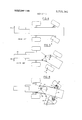
- FIG. 1 is a side elevational view of a self-propelled trencher embodying the present invention
- FIG. 2 is a generally schematic plan view of the trencher shown in FIG. 1, on a reduced scale;
- FIG. 3 is a view similar to FIG. 2, but showing the trencher when making a turn;
- FIG. 4 is a generally schematic view of a conventional rigid frame trencher employing Ackerman type steering
- FIG. 5 is a schematic showing of a prior art vehicle which utilizes only articulated frame type steering.
- FIG. 6 is a schematic plan view of a self-propelled trencher made in accordance with the present invention and employing combined articulated steering with Ackerman type steering.
- the general organization of the self-propelled trencher includes an articulated frame vehicle V having a trencher means TM extending rearwardly therefrom.
- the vehicle is of the four wheel type which provides good stability, and may be of the two-wheel drive type, although the present invention enables the use of a four wheel drive vehicle, as shown.
- the vehicle itself includes a front frame portion F and a rear frame portion R, which portions are pivotally attached at their adjacent ends and about a generally vertical, pivot axis 3.
- the front frame portion has a pair of laterally spaced steerable wheels 4 and 5 which are mounted to opposite ends of the front drive axle 6 by conventional steering knuckles and king pins 7 and 8, respectively,
- One of the king pins has a steering arm 9 fixed thereto and a connecting drag link 10 is pivotally connected to arm 9 and to the rear frame portion, as at 12.
- the point 12 is located more closely to the vertical pivot 3 than it is to the rear axle, as viewed in plan.
- the distance between pivot axis 3 and point 12 may vary depending on the steering arm length and other dimensions such as the exact location of axis 3.
- the steerable wheels 4 and 5 are also connected together by the conventional tie rod 14.
- a power plant such as an internal combustion engine E, is also mounted on the front frame portion and an operators seat S is located directly over the vertical pivot 3.
- a hydraulic pump P is located on the front frame portion and is driven by the engine in the known manner to provide pressurized fluid to the hydraulic circuit of the vehicle for operating various components thereof.
- the rear frame portion of the vehicle has a pair of laterally spaced wheels 20 and 21 on a rear drive axle 22. Both pairs of front and rear wheels are driven from the centrally located transmission 23, which receives power from the engine E, and through the universal jointed drive shafts 24 and 25.
- a double acting hydraulic cylinder unit 30 is pivotally connected at one end to the rear frame as at 31 and is pivotally connected at its other end to the front frame as at 32.
- This cylinder unit 30 is actuated by pressurized fluid from pump P in the known manner and under the control of the operator.
- articulated frame steering is provided by actuation of the hydraulic unit 30, the front frame section being swingable about the pivot 3 and relative to the rear frame portion. In addition to this articulated frame type of steering, when the front frame portion is swung relative to the rear frame.
- the steerable front wheels are actuated by the connecting drag link 10, the steering arm 9, and the tie rod 14.
- the connecting drag link 10 causes the steering arm 9 to swing, carrying with it the wheel 5 and, through the tie rod 14, the wheel 4.
- the trenching means TM is of the conventional type and includes a rearwardly extending boom 40 pivoted to the rear frame portion at 41 and is swingable from a lower position in the trench and an upper position out of the trench for transport.
- An endless digging chain 44 is trained around the boom and is driven in the conventional manner to dig the trench and convey the spoil to the upper surface of the ground G as the vehicle moves therealong.
- An auger 46 may also be provided to disperse the loose earth laterally of the trench.
- the vehicle also has a front mounted blade 48 which may be used, for example, for back-filling of the trench.
- the blade is vertically positioned in the conventional manner by a power means such as fluid cylinder and piston means (not shown), and is generally arranged transversely across the front frame portion and may also be adjusted as to its transverse angle with respect to the vehicle.
- a power means such as fluid cylinder and piston means (not shown)
- the blade is on the ground and the weight of the vehicle may be imposed thereon, and frequently the front wheels are then lifted off the ground. Under these circumstances, steering ability is often lost with prior art vehicles.
- the present articulated vehicle steering arrangement the present articulated vehicle steering arrangement, the
- FIG. 4 illustrates a prior art type oftrencher embodying a rigid frame vehicle with Ackerman type steering only. It will be seen that when the vehicle is to be turned to the right, lateral side trust, indicated by the arrow 50, against the trench outer wall occurs as the turn progresses, due to the swinging action of the trencher boom 51. This side thrust makes it difficult to maneuver the vehicle and severely limits the turning ability when trenching. The amount of turning of the wheels is indicated by the angle a.
- FIG. 5 shows a trencher when utilizing only articulated frame steering and when the vehicle is initially turning to the right, a lateral side thrust as indicated by arrow 60 is imposed against the inner side wall of the trench by the boom 61.
- the amount of turning of the wheels is indicated by the angle 3.
- FIG. 6 A schematic representation of the invention employing combined steering of the trencher is shown in FIG. 6. Initially the trenching mechanism is not crowded as severely against the inside of the curve. The increased amount of turning of the wheels due to the combined steering is indicated by the angles a plus B. At the time the position of the front wheels relative to the front frame portion is such that they are widely spaced and and forwardly of the frame, thus providing good vehicle stability.
- the trencher provided by the present invention also locates the vertical pivot point 3 between the front and rear frame portions at a distance approximately onethird of the wheel base length forwardly of the center of the rear frame portion wheels. Furthermore, the connection at point 12 between the drag link and rear frame is located more closely adjacent the pivot point 3 than it is to the rear axle, as viewed in plan.
- This construction provides good tracking ability, that is to say, it permits the rear wheels to track readily with the front wheels, and this is important particularly when used with a four-wheel drive vehicle because tire scuffing, wheel spinning, or wind up is reduced. Furthermore, this arrangement permits the use of a transmission without the necessity of having an inter-axle differential, resulting in better traction.
- the rearwardly located pivot permits more room to mount the transmission generally amidships, and the transmission and the transmission driving means can both be mounted on the same end of the vehicle along with the engine and hydraulic pump, thereby minimizing the number of parts required and particularly plumbing between the engine and pump.
- the operator can be located directly over the vertical pivot 3 and thereby less lateral movement of the operator occurs than with a contilevered location of the operator with respect to the pivot point. This particular location of the vertical pivot point also insures that the engine can be moved further to the rear, thereby reducing engine over-hang and which thereby permits the mounting of the backfill blade' closer to the front wheels and consequently minimizing turning moment due to side draft effect on the front mounted blade.
- the combined steering effect provided by the present invention in such a trencher insures good stability of the vehicle, no hazard to the operator due to interference with the scissor action of the vehicle frames, less severe universal joint angles in the drive mechanism and more stable and comfortable operators positions between the axles of such a trencher.
- a self-propelled trencher and backfiller comprising:
- a front frame portion having thereon a power operated back-fill blade generally transversely across the front end of said front frame portion
- trenching means extending rearwardly and being shiftable from a lower trench digging position to a raised transport position
- pivot means connecting said front and rear frame portions together for swinging movement about a generally vertical axis
- said pivot means connecting said front and rear frame portions together being located to position said generally vertical axis a substantial distance rearwardly of the midpoint of the wheel base length to permit said wheels on said rear frame portion to substantially track said wheels on said front frame portion during turns induced by said combined steering effect.
- a self-propelled trencher and back-filler according to claim 1 additionally including an operators seat located directly above said pivot means.
Landscapes
- Engineering & Computer Science (AREA)
- Mechanical Engineering (AREA)
- Mining & Mineral Resources (AREA)
- Civil Engineering (AREA)
- General Engineering & Computer Science (AREA)
- Structural Engineering (AREA)
- Chemical & Material Sciences (AREA)
- Combustion & Propulsion (AREA)
- Transportation (AREA)
- Steering-Linkage Mechanisms And Four-Wheel Steering (AREA)
- Body Structure For Vehicles (AREA)
Applications Claiming Priority (1)
| Application Number | Priority Date | Filing Date | Title |
|---|---|---|---|
| US25075672A | 1972-05-05 | 1972-05-05 |
Publications (1)
| Publication Number | Publication Date |
|---|---|
| US3771241A true US3771241A (en) | 1973-11-13 |
Family
ID=22949007
Family Applications (1)
| Application Number | Title | Priority Date | Filing Date |
|---|---|---|---|
| US00250756A Expired - Lifetime US3771241A (en) | 1972-05-05 | 1972-05-05 | Steering mechanism for trencher |
Country Status (3)
| Country | Link |
|---|---|
| US (1) | US3771241A (en:Method) |
| DE (1) | DE2322126A1 (en:Method) |
| FR (1) | FR2183798A1 (en:Method) |
Cited By (24)
| Publication number | Priority date | Publication date | Assignee | Title |
|---|---|---|---|---|
| US4042053A (en) * | 1974-12-24 | 1977-08-16 | Allis-Chalmers Corporation | Four-wheel drive tractor |
| US4100990A (en) * | 1977-04-28 | 1978-07-18 | Caterpillar Tractor Co. | Steering apparatus |
| US4351408A (en) * | 1978-12-05 | 1982-09-28 | Man Maschinenfabrik Augsburg-Nurnberg Ag | Articulated vehicle |
| US4565257A (en) * | 1984-02-08 | 1986-01-21 | J. I. Case Company | Multi-mode steering system |
| US4802545A (en) * | 1986-10-15 | 1989-02-07 | J. I. Case Company | Steering control system for articulated vehicle |
| EP0485732A3 (en) * | 1990-11-14 | 1992-08-05 | Liebherr-Werk Bischofshofen Gmbh | Building site vehicle with central pivot steering, especially wheel loader |
| US5496135A (en) * | 1994-03-01 | 1996-03-05 | C. Darrin Godsey | Articulated vehicle for use in confining trench work |
| GB2347657A (en) * | 1999-03-09 | 2000-09-13 | Colin Fraser Mckay | Articulated steering system |
| WO2002075060A1 (de) * | 2001-03-20 | 2002-09-26 | O & K Orenstein & Koppel Aktiengesellschaft | Radbagger |
| US6658768B1 (en) * | 2001-05-19 | 2003-12-09 | Wesley Allen Bainter | Trencher |
| WO2003097946A3 (en) * | 2002-05-17 | 2004-04-15 | Wasley Allen Bainter | Trencher |
| US20040172865A1 (en) * | 2003-02-04 | 2004-09-09 | Bainter Wesley Allen | Trencher unit |
| US20070089329A1 (en) * | 2005-10-22 | 2007-04-26 | Sigmund Richard W Sr | Walk behind trencher for limited depth installations |
| US20070132204A1 (en) * | 2005-12-13 | 2007-06-14 | Sewell Cody L | Compact Tool Carrier with Articulation Joint |
| US20090308669A1 (en) * | 2007-10-15 | 2009-12-17 | Vermeer Manufacturing Company | Quad track vehicle |
| US8430188B2 (en) | 2006-12-11 | 2013-04-30 | Vermeer Manufacturing Company | Apparatus for converting a wheeled vehicle to a tracked vehicle |
| US8801115B2 (en) | 2008-12-09 | 2014-08-12 | Vermeer Manufacturing Company | Apparatus for converting a wheeled vehicle to a tracked vehicle |
| EP3053811A1 (en) | 2015-02-03 | 2016-08-10 | Vermeer Manufacturing Company | Tractor with track drive |
| US9643667B2 (en) | 2006-12-12 | 2017-05-09 | A.S.V., Llc | Conversion system for a wheeled vehicle |
| EP3296249A1 (de) * | 2016-09-15 | 2018-03-21 | Liebherr-Werk Bischofshofen GmbH | Artikulierte arbeitsmaschine |
| US10100488B2 (en) * | 2015-05-14 | 2018-10-16 | Kubota Corporation | Front loader, support frame for a front loader and method |
| US20190016380A1 (en) * | 2017-07-14 | 2019-01-17 | Mario Gullo | Rear Wheel Steering System |
| US20210078633A1 (en) * | 2019-09-18 | 2021-03-18 | Deere & Company | Reverse steering modes for agricultural vehicles |
| US11667326B2 (en) * | 2019-09-18 | 2023-06-06 | Deere & Company | Automatic guidance performance improvement and transport with articulated machine form |
Citations (7)
| Publication number | Priority date | Publication date | Assignee | Title |
|---|---|---|---|---|
| US2827715A (en) * | 1955-09-23 | 1958-03-25 | Wagner Tractor Inc | Logging apparatus |
| CA650730A (en) * | 1962-10-23 | J. Jordan Elmer | Steering mechanism | |
| US3151694A (en) * | 1961-05-11 | 1964-10-06 | Clark Equipment Co | Steering arrangement and hydrostatic drive for articulated vehicle |
| US3380547A (en) * | 1964-12-23 | 1968-04-30 | Int Harvester Co | Steering system |
| US3605903A (en) * | 1969-07-25 | 1971-09-20 | Omsteel Ind Inc | Speed control system for a vehicle |
| US3605908A (en) * | 1968-03-28 | 1971-09-20 | Pettibone Corp | Forestry work vehicle |
| US3612310A (en) * | 1968-06-20 | 1971-10-12 | Schaeff Kg Maschfab Karl | Dredging loader |
-
1972
- 1972-05-05 US US00250756A patent/US3771241A/en not_active Expired - Lifetime
-
1973
- 1973-05-02 DE DE2322126A patent/DE2322126A1/de active Pending
- 1973-05-04 FR FR7316123A patent/FR2183798A1/fr not_active Withdrawn
Patent Citations (7)
| Publication number | Priority date | Publication date | Assignee | Title |
|---|---|---|---|---|
| CA650730A (en) * | 1962-10-23 | J. Jordan Elmer | Steering mechanism | |
| US2827715A (en) * | 1955-09-23 | 1958-03-25 | Wagner Tractor Inc | Logging apparatus |
| US3151694A (en) * | 1961-05-11 | 1964-10-06 | Clark Equipment Co | Steering arrangement and hydrostatic drive for articulated vehicle |
| US3380547A (en) * | 1964-12-23 | 1968-04-30 | Int Harvester Co | Steering system |
| US3605908A (en) * | 1968-03-28 | 1971-09-20 | Pettibone Corp | Forestry work vehicle |
| US3612310A (en) * | 1968-06-20 | 1971-10-12 | Schaeff Kg Maschfab Karl | Dredging loader |
| US3605903A (en) * | 1969-07-25 | 1971-09-20 | Omsteel Ind Inc | Speed control system for a vehicle |
Cited By (36)
| Publication number | Priority date | Publication date | Assignee | Title |
|---|---|---|---|---|
| US4042053A (en) * | 1974-12-24 | 1977-08-16 | Allis-Chalmers Corporation | Four-wheel drive tractor |
| US4100990A (en) * | 1977-04-28 | 1978-07-18 | Caterpillar Tractor Co. | Steering apparatus |
| FR2388710A1 (fr) * | 1977-04-28 | 1978-11-24 | Caterpillar Tractor Co | Appareil de direction |
| US4351408A (en) * | 1978-12-05 | 1982-09-28 | Man Maschinenfabrik Augsburg-Nurnberg Ag | Articulated vehicle |
| US4565257A (en) * | 1984-02-08 | 1986-01-21 | J. I. Case Company | Multi-mode steering system |
| US4802545A (en) * | 1986-10-15 | 1989-02-07 | J. I. Case Company | Steering control system for articulated vehicle |
| EP0485732A3 (en) * | 1990-11-14 | 1992-08-05 | Liebherr-Werk Bischofshofen Gmbh | Building site vehicle with central pivot steering, especially wheel loader |
| US5496135A (en) * | 1994-03-01 | 1996-03-05 | C. Darrin Godsey | Articulated vehicle for use in confining trench work |
| GB2347657A (en) * | 1999-03-09 | 2000-09-13 | Colin Fraser Mckay | Articulated steering system |
| WO2002075060A1 (de) * | 2001-03-20 | 2002-09-26 | O & K Orenstein & Koppel Aktiengesellschaft | Radbagger |
| US6658768B1 (en) * | 2001-05-19 | 2003-12-09 | Wesley Allen Bainter | Trencher |
| US20040128869A1 (en) * | 2001-05-19 | 2004-07-08 | Bainter Wesley Allen | Trencher |
| WO2003097946A3 (en) * | 2002-05-17 | 2004-04-15 | Wasley Allen Bainter | Trencher |
| GB2406872A (en) * | 2002-05-17 | 2005-04-13 | Wesley Allen Bainter | Trencher |
| GB2406872B (en) * | 2002-05-17 | 2005-12-21 | Wesley Allen Bainter | Trencher |
| US20040172865A1 (en) * | 2003-02-04 | 2004-09-09 | Bainter Wesley Allen | Trencher unit |
| US7096609B2 (en) | 2003-02-04 | 2006-08-29 | Wesley Allen Bainter | Trencher unit |
| US20070089329A1 (en) * | 2005-10-22 | 2007-04-26 | Sigmund Richard W Sr | Walk behind trencher for limited depth installations |
| US20070132204A1 (en) * | 2005-12-13 | 2007-06-14 | Sewell Cody L | Compact Tool Carrier with Articulation Joint |
| US8485287B2 (en) * | 2005-12-13 | 2013-07-16 | The Charles Machine Works, Inc. | Compact tool carrier with articulation joint |
| US8430188B2 (en) | 2006-12-11 | 2013-04-30 | Vermeer Manufacturing Company | Apparatus for converting a wheeled vehicle to a tracked vehicle |
| US8827013B2 (en) | 2006-12-11 | 2014-09-09 | Vermeer Manufacturing Company | Apparatus for converting a wheeled vehicle to a tracked vehicle |
| US9079614B2 (en) | 2006-12-11 | 2015-07-14 | Vermeer Manufacturing Company | Apparatus for converting a wheeled vehicle to a tracked vehicle |
| US9180910B2 (en) | 2006-12-11 | 2015-11-10 | Vermeer Manufacturing Company | Apparatus for converting a wheeled vehicle to a tracked vehicle |
| US9352776B2 (en) | 2006-12-11 | 2016-05-31 | Vermeer Manufacturing Company | Apparatus for converting a wheeled vehicle to a tracked vehicle |
| US9643667B2 (en) | 2006-12-12 | 2017-05-09 | A.S.V., Llc | Conversion system for a wheeled vehicle |
| US20090308669A1 (en) * | 2007-10-15 | 2009-12-17 | Vermeer Manufacturing Company | Quad track vehicle |
| US8801115B2 (en) | 2008-12-09 | 2014-08-12 | Vermeer Manufacturing Company | Apparatus for converting a wheeled vehicle to a tracked vehicle |
| EP3053811A1 (en) | 2015-02-03 | 2016-08-10 | Vermeer Manufacturing Company | Tractor with track drive |
| US10150523B2 (en) | 2015-02-03 | 2018-12-11 | Vermeer Manufacturing Company | Tractor with track drive |
| US10100488B2 (en) * | 2015-05-14 | 2018-10-16 | Kubota Corporation | Front loader, support frame for a front loader and method |
| EP3296249A1 (de) * | 2016-09-15 | 2018-03-21 | Liebherr-Werk Bischofshofen GmbH | Artikulierte arbeitsmaschine |
| US20190016380A1 (en) * | 2017-07-14 | 2019-01-17 | Mario Gullo | Rear Wheel Steering System |
| US20210078633A1 (en) * | 2019-09-18 | 2021-03-18 | Deere & Company | Reverse steering modes for agricultural vehicles |
| US11667326B2 (en) * | 2019-09-18 | 2023-06-06 | Deere & Company | Automatic guidance performance improvement and transport with articulated machine form |
| US11702136B2 (en) * | 2019-09-18 | 2023-07-18 | Deere & Company | Reverse steering modes for agricultural vehicles |
Also Published As
| Publication number | Publication date |
|---|---|
| FR2183798A1 (en:Method) | 1973-12-21 |
| DE2322126A1 (de) | 1973-11-22 |
Similar Documents
| Publication | Publication Date | Title |
|---|---|---|
| US3771241A (en) | Steering mechanism for trencher | |
| US4042053A (en) | Four-wheel drive tractor | |
| US4565257A (en) | Multi-mode steering system | |
| US3527315A (en) | Articulated motor grader | |
| US3057319A (en) | Rough terrain amphibious vehicle | |
| US5778569A (en) | Multi-purpose construction vehicle with at least two subframes and a self-aligning bearing between the subframes | |
| US20070240928A1 (en) | Compact construction vehicle with improved mobility | |
| EP1607527B1 (en) | Steering control system for a skid steer vehicle. | |
| US3370670A (en) | Oscillatable and laterally shiftable drive axles provided with steerable wheels | |
| KR100503840B1 (ko) | 휠식 작업기 | |
| US4571147A (en) | Shovel excavator with modified upper carriage design | |
| WO1998032928A1 (fr) | Perfectionnement aux tracto-pelles | |
| US8910741B2 (en) | Steering device for tractor | |
| US3431741A (en) | Articulated vehicle | |
| US4116298A (en) | Angled roll axis suspension for off-road vehicles | |
| US3966255A (en) | Bottom dump vehicle | |
| US3349864A (en) | Transmission mounting in an articulated vehicle | |
| US3631615A (en) | Crawler tractor-scraper combination | |
| US8978810B2 (en) | Tractor | |
| CN113135220B (zh) | 轴组件 | |
| US2631737A (en) | Highway crane | |
| CN104853976B (zh) | 工作车辆 | |
| US3047307A (en) | Tractor steering arrangement | |
| EP0003655B1 (en) | Tractors and fittings therefor | |
| CA1048939A (en) | Four-wheel drive tractor |