US3768692A - Container easy-open structure - Google Patents
Container easy-open structure Download PDFInfo
- Publication number
- US3768692A US3768692A US00073344A US3768692DA US3768692A US 3768692 A US3768692 A US 3768692A US 00073344 A US00073344 A US 00073344A US 3768692D A US3768692D A US 3768692DA US 3768692 A US3768692 A US 3768692A
- Authority
- US
- United States
- Prior art keywords
- scoreline
- opening member
- securing means
- container wall
- container
- Prior art date
- Legal status (The legal status is an assumption and is not a legal conclusion. Google has not performed a legal analysis and makes no representation as to the accuracy of the status listed.)
- Expired - Lifetime
Links
- 230000009471 action Effects 0.000 claims abstract description 28
- 229910052751 metal Inorganic materials 0.000 claims description 41
- 239000002184 metal Substances 0.000 claims description 41
- 230000003014 reinforcing effect Effects 0.000 claims description 19
- 239000000463 material Substances 0.000 claims description 11
- 230000003292 diminished effect Effects 0.000 claims description 9
- 239000007858 starting material Substances 0.000 abstract description 15
- 238000010008 shearing Methods 0.000 abstract description 7
- 239000012141 concentrate Substances 0.000 abstract description 3
- 229910001209 Low-carbon steel Inorganic materials 0.000 description 4
- 229910000831 Steel Inorganic materials 0.000 description 3
- 239000010959 steel Substances 0.000 description 3
- 229910052782 aluminium Inorganic materials 0.000 description 2
- XAGFODPZIPBFFR-UHFFFAOYSA-N aluminium Chemical compound [Al] XAGFODPZIPBFFR-UHFFFAOYSA-N 0.000 description 2
- 230000000694 effects Effects 0.000 description 2
- 150000002739 metals Chemical class 0.000 description 2
- 230000009467 reduction Effects 0.000 description 2
- 230000008439 repair process Effects 0.000 description 2
- 244000208734 Pisonia aculeata Species 0.000 description 1
- -1 aluminum Chemical class 0.000 description 1
- 229910000423 chromium oxide Inorganic materials 0.000 description 1
- 239000011248 coating agent Substances 0.000 description 1
- 238000000576 coating method Methods 0.000 description 1
- 230000000881 depressing effect Effects 0.000 description 1
- 230000003993 interaction Effects 0.000 description 1
- 230000004048 modification Effects 0.000 description 1
- 238000012986 modification Methods 0.000 description 1
- 230000001681 protective effect Effects 0.000 description 1
Images


Classifications
-
- B—PERFORMING OPERATIONS; TRANSPORTING
- B65—CONVEYING; PACKING; STORING; HANDLING THIN OR FILAMENTARY MATERIAL
- B65D—CONTAINERS FOR STORAGE OR TRANSPORT OF ARTICLES OR MATERIALS, e.g. BAGS, BARRELS, BOTTLES, BOXES, CANS, CARTONS, CRATES, DRUMS, JARS, TANKS, HOPPERS, FORWARDING CONTAINERS; ACCESSORIES, CLOSURES, OR FITTINGS THEREFOR; PACKAGING ELEMENTS; PACKAGES
- B65D17/00—Rigid or semi-rigid containers specially constructed to be opened by cutting or piercing, or by tearing of frangible members or portions
- B65D17/28—Rigid or semi-rigid containers specially constructed to be opened by cutting or piercing, or by tearing of frangible members or portions at lines or points of weakness
- B65D17/401—Rigid or semi-rigid containers specially constructed to be opened by cutting or piercing, or by tearing of frangible members or portions at lines or points of weakness characterised by having the line of weakness provided in an end wall
- B65D17/4011—Rigid or semi-rigid containers specially constructed to be opened by cutting or piercing, or by tearing of frangible members or portions at lines or points of weakness characterised by having the line of weakness provided in an end wall for opening completely by means of a tearing tab
Definitions
- US. Cl. 220/54 opener in aligned relationship with a Starter Section f
- an outer sc'oreline which d fi a removable area of Search
- the dire tion of the outer coreline from the narrow 215/46 A starter section through a wedge-shaped portion provides for a shearing action along the scoreline in place
- the disc pull-out concept generally encompasses removal of a portion of a wall of a container as a panel, that is without forming a spiral of metal.
- An early embodiment of the disc pull-out concept is shown in the patent to Khoury issued May 30, 1967, US. Pat. No. 3,322,296.
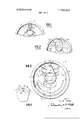
- FIGS. 1 and 2 are partial views of prior art pull-out container structures
- FIG. 3 is a planar view of easy-open container structure embodying the present invention.
- FIG. 4 is an enlarged view of a portion of the structure of FIG. 3,
- FIGS. 5 through 8 are sequential operation views for depicting operation of the present invention.
- FIG. 9 is a perspective view of a container endwall portion after removal in accordance with the present invention.
- FIG. 10 is a side elevation of a container endwall portion after removal in accordance with the teaching of the present invention.
- FIG. 11 is a top plan view of a tab opener of the present invention.
- FIG. 12 is a bottom plan view of the tab opener of FIG. 11,
- FIG. 13 is an enlarged plan view of a portion of the tab opener of FIG. 11, and
- FIG. 14 is an enlarged side elevational view of a portion of the tab opener of FIG. 11.
- FIG. 2 shows a prior art configuration employing an inner scoreline with terminating ends 25 and 26.
- a problem of overcoming tensile strength similar to that of FIG. 1 exists because the ends of the inner scoreline at 25 and 26 lead to a concentration of force at these points which causes the endwall to bulge outwardly. Such outward bulging presents and maintains a configuration such that the scoreline residual metal must be pulled apart under tension.
- Results differ drastically with the present invention shown in planar view of a container endwall 28 in FIG. 3.
- Endwall 28 is scored with an outer scoreline defining a removable area suitable for full-open uses, notwithstanding a predetermined inward spacing of portions of such outer scoreline to provide unusual advantages.
- This outer scoreline includes: a small-radius starter section 29, a wedge-shaped portion formed by rectilinear legs 30 and 31, and a semi-circular portion 32.
- Starter section 29 is at the apex of legs 30 and 31.
- Semicircular portion 32 is in closely spaced relationship to the outer periphery of the endwall 28.
- a curved intermediate portion interconnects each leg to the semi-circular portion.
- Tab opener 34 includes a working end 35 and a handle end 36; it defines a finger opening 37 which is circular in configuration. Tab opener 34 is held to removable portion 38 of the endwall by rivet 39 which, in the case of sheet metal, is usually unitary and formed from metal of the removable area 38.
- Raised protrusions 40 and 41 substantially constrain pivotal movement of tab opener 34 around unitary rivet 39 so as to maintain alignment of the working end of tab opener 34 with the matching configuration of starter section 29.
- a significant contribution toward maintaining a shearing action during the early pull-back" stages stems from the wedge-shape configuration of the outer scoreline and from the configuration of reinforcing ribs and their placement substantially within the wedgeshaped portion of the scoreline. Note that this profiling for the endwall in the form of radius ribs 44, 45 and 46 has predominantly arcuate configurations in plan view. These arcuate ribs, flat curved about a far removed center, aid the specially shaped score in providing shear action by holding down the central portion of the removal panel and preventing the bulging of the prior art.
- Additional endwall profiling which aids in control of pull-out includes a finger placement depression 48 having a curvilinear border portion 49 and a substantially straight border portion 50. Also, note straight profile line 52 intermediate these two. Profile line 52 if extended as shown in dotted lines would meet terminating ends 53 and 54 of the semi-circular reinforcing rib 55.
- FIG. 4 a portion of the specific embodiment of FIG. 3 is shown from the internal side of the container. Note the limited length of inner scoreline 60. Also, its close proximity to integral rivet 39 which it only partially circumscribes. Inner scoreline 60 circumscribes less than half of the rivet and generally less than about a third. In fact, the included angle between radii extending from the center of rivet 39 to the ends of inner scoreline 60 is preferably about 75. Dotted line 62 and inner scoreline 60 define a segment 64 of the endwall which is turned inwardly of the container during initial rupturing. A shaded impression area 66 designates the area of concentrated force for initial rupture of the outer scoreline. The working end of the tab 34 is aligned with the starter section 29 of the outer scoreline and the force is concentrated at such area which is as close as practicable to the scoreline starter section 29.
- FIGS. through will be referred to in describing the sequence of steps involved in opening a container and the function of the individual elements of the struc ture designated.
- the endwall and removable portion are shown without the tab opener for better viewing since it will be understood from the description of these figures how the functions of the tab opener come into play.
- FIG. 5 shows the endwall 28 with removable portion 38, the outer scoreline starter portion 29, rectilinear scoreline legs 30 and 31, and semicircular scoreline portion 32
- the removable area 38 can be divided into sections related to parts of the scoreline and the operations which take place.
- the first section is segment 64 which is folded downwardly into the container as indicated by FIG. 6 during the initial opening operation when the handle or input end of the tab opener is raised.
- wedge section 68 The angular, wedge-configuration portion of the removable panel from segment 64 through the arcuate rib profiling portion to the ends of the rectilinear legs 30 and 31 has been designated wedge section 68.
- the radius ribs stiffen this section during removal to prevent outward bulging.
- raising of the handle i.e., the working end of the tab
- raising of the handle causes rupture of the inner score-line 60 and the starter portion 29 of the outer scoreline.
- This initial rupture causes segment 64 to be turned inwardly of the container as shown in FIG. 6.
- the tab is pulled backwardly and the removable portion separates from the endwall along the rectilinear legs 30 and 31 as shown in FIG. 7.
- the profiling ribs 44, 45 and 46 not only prevent doming or bulging outwardly of the lid but tend to effect an inward configuration on the lid. Because of the angle along lines 30 and 31, the metal can be parted in shear along the scoreline legs 30 and 31, rather than being stretched apart in tensron.
- the elements and features described combine to provide an ease of opening not previously available.
- the inner scoreline, ruptured by initial movement of the workingend of the handle by class 2 lever action eliminates the back tension which in some earlier structures inhibited the class 1 lever action for the outer scoreline.
- Metal at starter portion 29 is ruptured by class I lever action. Note that this portion is aligned with and partially circumscribes rivet 39. A concentration of force is thus possible which facilitates initial rupture.
- FIGS. 11 through 14 A significant contribution to the easy-open characteristics of the present invention is made by a chisel pointed tab opener forming part of the present invention and shown in detail in FIGS. 11 through 14.
- the ring pull tab opener 34 includes working end 35, having a rounded configuration in plan conforming to the configuration of starter scoreline 29 of the outer scoreline of the wall. From the working end the tab opener 34 widens through the body portion 83 going toward the handle end 36. At the working end 35 is a chisel point 84, which will be described in more detail in relation to the enlarged views of FIGS. 13 and 14. At the handle end 36, a raised portion 86 is provided for ease in initial placement of a finger under the tab opener.
- the tab opener 34 would conventionally be made from the material of the container wall to which it is at.- tached. Ordinarily this will be sheet metal of equal or greater strength than the sheet metal of the container. Since the tab opener is required to function as a lever,
- wrap-around edge is shown in the bottom plan view of FIG. 12.
- Edge metal of the tab handle is wrapped around and folded over along the entire outer periphery 88 and the inner periphery of the ring at 90. This provides longitudinal strength for the lever action of the tab opener and also protects the user in providing a smooth rounded edge for finger contact.
- chisel point 84 Utilizing wrap-around edge metal placed at the rounded working end 35, chisel point 84 is formed by depressing the metal at 84 while supporting the metal adjacent thereto at 86 and 87.
- the resultant chisel point 84 consists of a double thickness of metal with a slightly rounded point configuration 88. Support adjacent to this chisel point is provided by the double thickness flattened portions 86 and 87.
- a high strength point able to withstand the concentration of force required to start opening results.
- the chisel point concentrates force at the center of impression 66 shown in FIG. 4. Because of the starter action of the chisel point and concentration of force at the scoreline portion 29, initial rupture is facilitated. The shearing action described earlier facilitates further opening upon pulling back of the tab opener.
- the depth of scoreline utilized can be reduced significantly.
- no greater residual metal thickness than about 0.0025 inch has been practical or attempted.
- residual metal thickness for flat rolled mild steel can be increased to 0.0035 inch, and higher, e.g., as high as 0.0038 inch while maintaining practical, easy-open features.
- Scoreline residual metal for other container sheet metals, such as aluminum, is correspondingly increased by the present invention.
- the diameter of the rivet stem is about 0.1 inch while the rivet head has a diameter of about 0.125 inch.
- the radius of the starter section 29 is about 0.150 inch.
- the invention is not limited to the specific endwall embodiment illustrated and other means may be provided for securing a tab opener to a container and for preventing pivotal movement of a riveted opener.
- the tab opener can also be other than the ring pull type.
- Other modifications, configurations, and materials than those mentioned are made possible by the teachings of the present invention, as described above, so that in determining the scope of the invention reference should be had to the appended claims.
- Container easy-open structure comprising a container wall, an outer scoreline of diminished material thickness located on the container wall defining a removable area of such wall, such outer scoreline including an apex portion and a wedge-shaped configuration portion having legs deviating from such apex portion, the container wall comprising a sheet metal endwall and the removable area of such endwall comprising a major portion of such endwall to provide full-open uses for such container, the endwall being bounded by a periphery with the wedge-shaped configuration portion of the outer scoreline being spaced from such periphery and the remaining major portion of the outer scoreline being in close proximity and uniformly spaced from such periphery, an inner scoreline of diminished material thickness and predetermined limited length located within the removable portion of the container wall, an opening member, and securing means securing the opening member to the removable portion of the container wall, the securing means comprising a unitary rivet formed from metal of the removable area of the container wall, the opening member including a handle end in spaced
- the apex portion of the outer scoreline being located, adjacent to the securing means aligned with the working end of the opening member, at a position to be ruptured with continued movement of the handle end of the opening member in a direction away from the container wall,
- Container easy-open structure comprising a sheet metal container wall
- securing means securing the opening member to the removable portion of the container wall
- the opening member including a handle end in spaced relationship from the securing means and a working end in close proximity to the securing means, the handle end and working end of the opening member being located on opposite sides of the securing means,
- wall reinforcing rib means of arcuate configuration positioned to extend across the removable area of the container wall and located substantially entirely on the same side of the securing means as the inner scoreline in at least partial circumscribing relationship to the securing means.
- the container wall comprises an endwall including additional reinforcing means located within the removable portion of the endwall and circumscribed by a portion of the outer scoreline adjacent to and uniformly spaced from the outer periphery of the endwall, such additional reinforcing means being diametrically opposed to the portion of the outer scoreline ruptured initially by movement of the handle end of the opening member.
- the additional reinforcing means includes a depression in the container endwall at the handle end of the opening member, such depression including a substantially straight line configuration having a direction transverse to a diametrical line through the initially ruptured portion of the outer scoreline.
- the additional reinforcing means also includes a semi-circular rib spaced from and substantially concentric with the outer periphery of the endwall, the semi-circular rib terminating at both its ends at a location near extension of the straight line configuration of the depression below the handle end of opening member.
- the structure of claim 5 including at least three arcuate reinforcing ribs.
Landscapes
- Engineering & Computer Science (AREA)
- Mechanical Engineering (AREA)
- Containers Opened By Tearing Frangible Portions (AREA)
- Closures For Containers (AREA)
Applications Claiming Priority (1)
| Application Number | Priority Date | Filing Date | Title |
|---|---|---|---|
| US7334470A | 1970-09-18 | 1970-09-18 |
Publications (1)
| Publication Number | Publication Date |
|---|---|
| US3768692A true US3768692A (en) | 1973-10-30 |
Family
ID=22113178
Family Applications (1)
| Application Number | Title | Priority Date | Filing Date |
|---|---|---|---|
| US00073344A Expired - Lifetime US3768692A (en) | 1970-09-18 | 1970-09-18 | Container easy-open structure |
Country Status (5)
| Country | Link |
|---|---|
| US (1) | US3768692A (enExample) |
| DE (1) | DE2146584A1 (enExample) |
| FR (1) | FR2106621B3 (enExample) |
| GB (1) | GB1365387A (enExample) |
| NL (1) | NL7112849A (enExample) |
Cited By (10)
| Publication number | Priority date | Publication date | Assignee | Title |
|---|---|---|---|---|
| US4047634A (en) * | 1973-08-21 | 1977-09-13 | Mcgeehin Robert | Lid having a separable panel |
| US5816429A (en) * | 1996-12-24 | 1998-10-06 | Kobayashi; Tadao | Container opening device |
| US5934498A (en) * | 1997-09-19 | 1999-08-10 | Aluminum Company Of America | Convenience easy opening end with large removal panel |
| US20060060582A1 (en) * | 2002-11-07 | 2006-03-23 | Estanislao Martinez Gomez | Easy-openning lid |
| US20080067174A1 (en) * | 2006-09-19 | 2008-03-20 | Crown Packaging Technology Inc. | Easy open can end with high pressure venting |
| US20080067171A1 (en) * | 2006-09-19 | 2008-03-20 | Heinicke Paul R | Easy open can end with high pressure venting |
| US20080314906A1 (en) * | 2007-06-22 | 2008-12-25 | Butcher Gregory H | Can end and method of making same |
| US20100213194A1 (en) * | 2009-02-21 | 2010-08-26 | Junsong Liu | Pop Can Beak Spout Design |
| US20100294812A1 (en) * | 2006-12-22 | 2010-11-25 | Portola Packaging, Inc | Internal container bore mount fitment |
| JP2023079929A (ja) * | 2021-11-29 | 2023-06-08 | 祐司 中原 | 飲料容器の蓋構造及び飲料容器 |
Families Citing this family (1)
| Publication number | Priority date | Publication date | Assignee | Title |
|---|---|---|---|---|
| US4386713A (en) * | 1982-02-24 | 1983-06-07 | Van Dorn Company | Full opening steel can end construction |
Citations (6)
| Publication number | Priority date | Publication date | Assignee | Title |
|---|---|---|---|---|
| US3341055A (en) * | 1965-10-22 | 1967-09-12 | Jafford Inc | Container opening device |
| FR1545647A (fr) * | 1967-07-19 | 1968-11-15 | Cebal Gp | Couvercle pour boîte à ouverture facile à ligne préincisée unique et languette perforante |
| US3478918A (en) * | 1968-08-14 | 1969-11-18 | American Can Co | Full open end closure |
| US3527378A (en) * | 1969-08-28 | 1970-09-08 | Crown Cork & Seal Co | Easy-opening closure |
| US3593875A (en) * | 1969-01-09 | 1971-07-20 | Ermal C Fraze | Tab for tear strip of container wall |
| US3616961A (en) * | 1970-04-30 | 1971-11-02 | Continental Can Co | Easy-opening container with pour spout |
-
1970
- 1970-09-18 US US00073344A patent/US3768692A/en not_active Expired - Lifetime
-
1971
- 1971-09-17 FR FR7133650A patent/FR2106621B3/fr not_active Expired
- 1971-09-17 GB GB4341571A patent/GB1365387A/en not_active Expired
- 1971-09-17 DE DE19712146584 patent/DE2146584A1/de active Pending
- 1971-09-17 NL NL7112849A patent/NL7112849A/xx unknown
Patent Citations (6)
| Publication number | Priority date | Publication date | Assignee | Title |
|---|---|---|---|---|
| US3341055A (en) * | 1965-10-22 | 1967-09-12 | Jafford Inc | Container opening device |
| FR1545647A (fr) * | 1967-07-19 | 1968-11-15 | Cebal Gp | Couvercle pour boîte à ouverture facile à ligne préincisée unique et languette perforante |
| US3478918A (en) * | 1968-08-14 | 1969-11-18 | American Can Co | Full open end closure |
| US3593875A (en) * | 1969-01-09 | 1971-07-20 | Ermal C Fraze | Tab for tear strip of container wall |
| US3527378A (en) * | 1969-08-28 | 1970-09-08 | Crown Cork & Seal Co | Easy-opening closure |
| US3616961A (en) * | 1970-04-30 | 1971-11-02 | Continental Can Co | Easy-opening container with pour spout |
Cited By (13)
| Publication number | Priority date | Publication date | Assignee | Title |
|---|---|---|---|---|
| US4047634A (en) * | 1973-08-21 | 1977-09-13 | Mcgeehin Robert | Lid having a separable panel |
| US5816429A (en) * | 1996-12-24 | 1998-10-06 | Kobayashi; Tadao | Container opening device |
| US5934498A (en) * | 1997-09-19 | 1999-08-10 | Aluminum Company Of America | Convenience easy opening end with large removal panel |
| US20060060582A1 (en) * | 2002-11-07 | 2006-03-23 | Estanislao Martinez Gomez | Easy-openning lid |
| US20080067174A1 (en) * | 2006-09-19 | 2008-03-20 | Crown Packaging Technology Inc. | Easy open can end with high pressure venting |
| US20080067171A1 (en) * | 2006-09-19 | 2008-03-20 | Heinicke Paul R | Easy open can end with high pressure venting |
| US7922025B2 (en) | 2006-09-19 | 2011-04-12 | Crown Packaging Company, L.P. | Easy open can end with high pressure venting |
| US7721906B2 (en) * | 2006-09-19 | 2010-05-25 | Crown Packaging Technology, Inc. | Easy open can end with high pressure venting |
| US20100294812A1 (en) * | 2006-12-22 | 2010-11-25 | Portola Packaging, Inc | Internal container bore mount fitment |
| US20080314906A1 (en) * | 2007-06-22 | 2008-12-25 | Butcher Gregory H | Can end and method of making same |
| US8109405B2 (en) * | 2007-06-22 | 2012-02-07 | Stolle Machinery Company, Llc | Can end and rivet base scoreline therefor |
| US20100213194A1 (en) * | 2009-02-21 | 2010-08-26 | Junsong Liu | Pop Can Beak Spout Design |
| JP2023079929A (ja) * | 2021-11-29 | 2023-06-08 | 祐司 中原 | 飲料容器の蓋構造及び飲料容器 |
Also Published As
| Publication number | Publication date |
|---|---|
| GB1365387A (en) | 1974-09-04 |
| DE2146584A1 (de) | 1972-03-23 |
| NL7112849A (enExample) | 1972-03-21 |
| FR2106621B3 (enExample) | 1974-05-10 |
| FR2106621A3 (enExample) | 1972-05-05 |
Similar Documents
| Publication | Publication Date | Title |
|---|---|---|
| US4361251A (en) | Detachment resistant retained lever tab | |
| US3967752A (en) | Easy-open wall | |
| US4207991A (en) | Can top opening means | |
| US3662916A (en) | Easy opening container | |
| US4211335A (en) | Fracture resistant retained lever tab and method of manufacture | |
| EP0223776B1 (en) | Can end structure and method of making | |
| US3838788A (en) | Can end construction | |
| US3744667A (en) | Can end with retained tear strip | |
| US4848623A (en) | Disc removal end wall structure with safety features | |
| US3307737A (en) | Attachment of an opener to the wall of a can | |
| US3618815A (en) | Easy-opening device for a container end | |
| US3768692A (en) | Container easy-open structure | |
| US3796344A (en) | Non-detachable tear strip and pull tab structure for easy opening container | |
| US3221923A (en) | Multi-paneled metal can-end with scored and beaded tear strip | |
| US2017460A (en) | Container and method of manufacture | |
| US3752353A (en) | Can end | |
| US3441171A (en) | Easy-opening container panel structure | |
| US3255917A (en) | Container opening device for metallic can ends | |
| USRE30349E (en) | Easy-opening container wall with coreline vent | |
| US3370169A (en) | Pull tab opener | |
| US3891117A (en) | Easy-opening can end construction | |
| US4044915A (en) | Container end closure | |
| US3720349A (en) | Easy opening container wall | |
| US3327891A (en) | Can end with inseparable tear strip | |
| US4258859A (en) | No-fin scored metal ends for containers |