US3765357A - All-terrain-vehicle - Google Patents
All-terrain-vehicle Download PDFInfo
- Publication number
- US3765357A US3765357A US00191721A US3765357DA US3765357A US 3765357 A US3765357 A US 3765357A US 00191721 A US00191721 A US 00191721A US 3765357D A US3765357D A US 3765357DA US 3765357 A US3765357 A US 3765357A
- Authority
- US
- United States
- Prior art keywords
- air
- hull
- pontoons
- vehicle
- vehicle according
- Prior art date
- Legal status (The legal status is an assumption and is not a legal conclusion. Google has not performed a legal analysis and makes no representation as to the accuracy of the status listed.)
- Expired - Lifetime
Links
- XLYOFNOQVPJJNP-UHFFFAOYSA-N water Substances O XLYOFNOQVPJJNP-UHFFFAOYSA-N 0.000 claims abstract description 20
- 230000000694 effects Effects 0.000 claims abstract description 15
- 239000000463 material Substances 0.000 claims description 4
- 230000015572 biosynthetic process Effects 0.000 claims description 3
- 239000002918 waste heat Substances 0.000 claims description 3
- 238000007599 discharging Methods 0.000 claims description 2
- 239000011148 porous material Substances 0.000 claims description 2
- 238000010276 construction Methods 0.000 description 4
- JOYRKODLDBILNP-UHFFFAOYSA-N Ethyl urethane Chemical compound CCOC(N)=O JOYRKODLDBILNP-UHFFFAOYSA-N 0.000 description 3
- 230000002411 adverse Effects 0.000 description 2
- XAGFODPZIPBFFR-UHFFFAOYSA-N aluminium Chemical compound [Al] XAGFODPZIPBFFR-UHFFFAOYSA-N 0.000 description 2
- 229910052782 aluminium Inorganic materials 0.000 description 2
- 239000004411 aluminium Substances 0.000 description 2
- 108010066114 cabin-2 Proteins 0.000 description 2
- 230000003247 decreasing effect Effects 0.000 description 2
- 239000003365 glass fiber Substances 0.000 description 2
- 230000007246 mechanism Effects 0.000 description 2
- 230000002829 reductive effect Effects 0.000 description 2
- 239000000725 suspension Substances 0.000 description 2
- PPBRXRYQALVLMV-UHFFFAOYSA-N Styrene Chemical compound C=CC1=CC=CC=C1 PPBRXRYQALVLMV-UHFFFAOYSA-N 0.000 description 1
- 239000004809 Teflon Substances 0.000 description 1
- 238000005299 abrasion Methods 0.000 description 1
- 238000010521 absorption reaction Methods 0.000 description 1
- 230000004308 accommodation Effects 0.000 description 1
- 230000009471 action Effects 0.000 description 1
- 230000008901 benefit Effects 0.000 description 1
- 230000008859 change Effects 0.000 description 1
- 238000002485 combustion reaction Methods 0.000 description 1
- 230000007423 decrease Effects 0.000 description 1
- 229920006248 expandable polystyrene Polymers 0.000 description 1
- 239000004744 fabric Substances 0.000 description 1
- 239000006260 foam Substances 0.000 description 1
- 230000008014 freezing Effects 0.000 description 1
- 238000007710 freezing Methods 0.000 description 1
- 239000002783 friction material Substances 0.000 description 1
- 238000009499 grossing Methods 0.000 description 1
- 238000010438 heat treatment Methods 0.000 description 1
- 239000007788 liquid Substances 0.000 description 1
- 238000000034 method Methods 0.000 description 1
- 230000004048 modification Effects 0.000 description 1
- 238000012986 modification Methods 0.000 description 1
- 238000005192 partition Methods 0.000 description 1
- 239000004033 plastic Substances 0.000 description 1
- 229920003023 plastic Polymers 0.000 description 1
- 239000011120 plywood Substances 0.000 description 1
- 229920002635 polyurethane Polymers 0.000 description 1
- 239000004814 polyurethane Substances 0.000 description 1
- 230000003014 reinforcing effect Effects 0.000 description 1
- 230000000284 resting effect Effects 0.000 description 1
- 230000000717 retained effect Effects 0.000 description 1
- 239000010802 sludge Substances 0.000 description 1
- 239000007787 solid Substances 0.000 description 1
- 239000002904 solvent Substances 0.000 description 1
- 230000007480 spreading Effects 0.000 description 1
- 230000003068 static effect Effects 0.000 description 1
- 239000002699 waste material Substances 0.000 description 1
Images


Classifications
-
- B—PERFORMING OPERATIONS; TRANSPORTING
- B60—VEHICLES IN GENERAL
- B60V—AIR-CUSHION VEHICLES
- B60V1/00—Air-cushion
- B60V1/04—Air-cushion wherein the cushion is contained at least in part by walls
- B60V1/043—Air-cushion wherein the cushion is contained at least in part by walls the walls being flexible
-
- B—PERFORMING OPERATIONS; TRANSPORTING
- B60—VEHICLES IN GENERAL
- B60V—AIR-CUSHION VEHICLES
- B60V1/00—Air-cushion
- B60V1/16—Flexible skirts
-
- B—PERFORMING OPERATIONS; TRANSPORTING
- B63—SHIPS OR OTHER WATERBORNE VESSELS; RELATED EQUIPMENT
- B63B—SHIPS OR OTHER WATERBORNE VESSELS; EQUIPMENT FOR SHIPPING
- B63B1/00—Hydrodynamic or hydrostatic features of hulls or of hydrofoils
- B63B1/16—Hydrodynamic or hydrostatic features of hulls or of hydrofoils deriving additional lift from hydrodynamic forces
- B63B1/18—Hydrodynamic or hydrostatic features of hulls or of hydrofoils deriving additional lift from hydrodynamic forces of hydroplane type
- B63B1/20—Hydrodynamic or hydrostatic features of hulls or of hydrofoils deriving additional lift from hydrodynamic forces of hydroplane type having more than one planing surface
-
- B—PERFORMING OPERATIONS; TRANSPORTING
- B63—SHIPS OR OTHER WATERBORNE VESSELS; RELATED EQUIPMENT
- B63B—SHIPS OR OTHER WATERBORNE VESSELS; EQUIPMENT FOR SHIPPING
- B63B1/00—Hydrodynamic or hydrostatic features of hulls or of hydrofoils
- B63B1/32—Other means for varying the inherent hydrodynamic characteristics of hulls
- B63B1/34—Other means for varying the inherent hydrodynamic characteristics of hulls by reducing surface friction
-
- Y—GENERAL TAGGING OF NEW TECHNOLOGICAL DEVELOPMENTS; GENERAL TAGGING OF CROSS-SECTIONAL TECHNOLOGIES SPANNING OVER SEVERAL SECTIONS OF THE IPC; TECHNICAL SUBJECTS COVERED BY FORMER USPC CROSS-REFERENCE ART COLLECTIONS [XRACs] AND DIGESTS
- Y02—TECHNOLOGIES OR APPLICATIONS FOR MITIGATION OR ADAPTATION AGAINST CLIMATE CHANGE
- Y02T—CLIMATE CHANGE MITIGATION TECHNOLOGIES RELATED TO TRANSPORTATION
- Y02T70/00—Maritime or waterways transport
- Y02T70/10—Measures concerning design or construction of watercraft hulls
Definitions
- a vehicle adapted to travel on both water and ice comprises: a vehicle hull; propulsion means carried by said hull; ski-like surfaces carried by said hull and mounted to permit their up-and-down movement relative to said hull; support means acting between said ski-like surfaces and said hull and arranged to provide at all times a substantial degree of support of the hull by the ski-like surfaces; fan means arranged to discharge air continuously into a space below said hull; and enclosure means arranged to restrict leakage of said air from below said hull; the arrangement being such that said air in said space below said hull can provide a considerable degree of support for said hull by an air cushion or ground effect, while permitting said ski-like surfaces to remain in contact with the ground and so provide both support and restraint against lateral movement of the hull relative to the ground.
- the present invention is directed to the problem of providing a relatively small, light and cheap vehicle which can travel over water, ice and snow. It will be appreciated that although air cushion vehicles have been developed which can meet this requirement, such vehicles necessarily are large and heavy and present serious operational problems such as lateral drift.
- a vehicle adapted to travel on both'water and ice comprises: a vehicle hull; propulsion means carried by said hull; skilike surfaces carried by said hull and mounted to permit their up-and-down movement relative to said hull; support means acting between said ski-like surfaces and said hull and arranged to provide at all times a substantial degree of support of the hull by the ski-like surfaces; fan means arranged to discharge air continuously into a space below said hull; and enclosure means arranged to restrict leakage of said air from below said hull; the arrangement being such that said air in said space below said hull can provide a considerable degree of support for said hull by an air cushion or ground effect, while permitting said ski-like surfaces to remain in contact with theground and so provide both support and restraint against lateral movement of the hull relative to the ground.
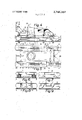
- FIG. I is a side elevation of an all-terrain vehicle according to the present invention.
- FIG. 2 is a plan view of the vehicle shown in FIG. 1;
- FIG. 3 is a front elevation of the vehicle shown in FIGS. 1 and 2, and is taken from the right-hand side of FIG. 1;
- FIG. 4 is a sectional side elevation of the vehicle, taken on the line IV-IV of FIG. 2 and as viewed in the direction indicated by the arrows;
- FIG. 5 is a sectional plan view taken on the line V-V of FIG. 4;
- FIGS, 6, 7 and 8 are transversesectional views of a lower part only of the vehicle, and are taken on the lines VI-VI, VII-VII, and VIII-VIII respectively of FIG. 4, and all as viewed in the direction indicated by the arrows;
- FIG. 9 is a sectional sideelevation taken on the line lX-IX of FIG. 5, and shows in side elevation a rear pontoon of the vehicle;
- FIG. 10 is a sectional side elevation of a modification of the vehicle in FIG. 1;
- FIGS. 11, 12 and 13 are transverse cross-sections taken respectively on the lines XI-XI, XII-XII and XlII-XIII of FIG. 10;
- FIGS. 14, I5 and 16 are side elevations illustrating the operation of front pontoons of the vehicle shown in FIG. 1;
- FIG. 17 is a side elevation illustrating a rear pontoon of the vehicle.
- the all-terrain vehicle shown includes a hull 1 on which is mounted a cabin 2.
- the hull is supported on two front ski-like pontoons 3 and on two rear ski-like pontoons 4.
- the surface over which the vehicle runs is indicated as surface 5, and it will be appreciated that in practice this surface may be rough or smooth, and it may be in the form of a solid, a liquid, a mud or slush.
- Each pontoon is connected to the hull on each side by at least one leaf-spring, and helical springs provide further support.
- each front pontoon 3 is associated with a helical spring 7 and with leaf springs 6, and each rear pontoon is associated with several helical springs 7 and with two leaf springs 6, as will be seen most clearly in FIGS. 4, 9, l4 and 17.
- the vehicle is driven by a propeller 8 surrounded by a rearwardly converging shroud 9 and driven by a motor 10.
- Motor 10 suitably an internal combustion engine, also drives a compressor 11 to which air flows through vertical duct 12, the upper end of which is provided with a hood or cowl 13 which can be turned into the prevailing wind.
- a duct 10a supplies waste heat from the motor 10 to the vertical duct 12.
- a rectangular cross-section air duct 14 is mounted under the hull 1, and air from the compressor 11 flows into this duct, from which it is discharged into a front air space, a rear air space, and two side air spaces.
- the vehicle is suspended partly by engagement of the pontoons with the surface 5, whatever its form, and partly by what is known as ground-effect, air being discharged continuously into the space below the hull and providing an upwards lift thereon. It is important to appreciate that, in normal operation, the lift supplied is purposely made insufficient to lift the pontoons off the surface 5.
- the cabin 2 can be made of plywood, aluminium or of plastic reinforced by glass fibers.
- the cabin had a length of 6 metres, a breadth of 3 metres and a height of L2 metres.
- the cabin was designed to provide room for the driver and for technical equipment, and also for sitting passengers as well as for sick pople in resting position on stretchers.
- Each front pontoon 3 has a length of 2 metres and a breadth of 0.5 metres, while each rear pontoon has a length of 3.5 metres and a breadth of 0.5 metres.
- Each pontoon is in the form of a shell formed of aluminium reinforced with glass fiber, and filled with a light material such as foamed polyurethane (URETAN) or foamed polystyrene (STYROL). It will be seen that a most important feature of each pontoon is the provision of a longitudinal groove or furrow in its undersurface, extending from the front end of the pontoon to its rear end.
- URETAN foamed polyurethane
- STYROL foamed polystyrene
- FIG. 9 shows how recesses are left in the pontoons for the accommodation of the leaf springs 6, which avoids the presence of supporting springs at the sides of the pontoons, where they could be damaged by rough parts of the surface 5.
- runners are particularly useful when the vehicle is passing over ice, while it has been found that such runners also provide good directional stability when the vehicle is operating over snow. In particular, sideways skidding of the pontoon is inhibited.
- the pontoon sinks into the snow only until the area engaging the snow is sufflcient to carry the weight on the pontoon.
- Air is supplied continuously through the central vertical duct shown in the pontoon to the interior of the longitudinal furrow, and this provides lift on the pontoon so reducing the weight which must be carried by the runners. This air also tends to reduce the friction between the water, sludge or snow and the runners.
- the remainder of the vehicle is supported by the leaf springs 6 and the helical springs 7 on the four pontoons, and it will be appreciated that the upper end of each of the leaf springs is fastened to the hull 1, and the lower ends of the springs are fastened to the pontoons.
- the fastening is such that the pontoon is able to rise and descent in a vertical direction; is able to become inclined in a fore-and-aft direction relative to the horizontal; and in the case of the front pontoons only, is able to turn to some extent in the horizontal plane. All movements of the pontoons, no matter how caused, take place against the biassing effect of the spring forces.
- the two front pontoons 3 are turnable by a steering wheel shown in FIG. 4, the necessary drive gear and linkage being shown in FIG. 5, together with arrows that indicate the to-and-fro movement of the mechanical linkage.
- This steering mechanism is such that turning of the front pontoons is combined with an inclination towards the inner curve.
- the hull 1 may change in its elevation relative to the surface by virtue of the ground effect or air cushion.
- the steering mechanism is therefore designed so that the track of the vehicle remains constant so that the steering is not adversely affected as the height of the hull 1 over the surface 5 changes.
- each pontoon can be provided with a readily replaceable bottom or slide, so that when inevitably this bottom becomes damaged, it can be replaced with a new part without replacing the whole pontoon.
- the motive power for the vehicle is derived from the motor which drives the propeller 8 through V-belts. Power from the motor 10 also drives the compressor 11, but of course, if desired a second motor can be used to drive the compressor.
- the flow of air to the compressor is indicated by the arrows, and it will be noted that the cowl 13 can be used not only to increase the final air pressure, by turning it into the direction of the prevailing wind, but also can be used to close the top of the duct 12 leading to the compressor, when the vehicle is not in use.
- each pontoon is to be capable of vertical movement relative to the hull I, it is connected to the hull through a superjacent compartment having flexible walls and communicating with the duct 14. The various springs lie inside this compartment. Some of the air from duct 14 passes down through these compartments and through vertical ducts in the pontoons to the furrows thereunder, to provide further lift.
- a flexible air bag 18 extends across the front of the vehicle between the two front pontoons 3, and has depending from it a flexible skirt which actually engages the surface 5, but which can be lifted free of that surface 5 by a wire control cable when so desired.
- This air bag 18 is also provided with an air discharge nozzle directed rearwardly of the skirt, through which air from the compressor is discharged continuously into the general space below the hull.
- a second air bag 16 extends between the two rear pontoons 4, and is provided with a second flexible skirt also raisable by a wire control cable when so desired. As shown in FIG. 8, this skirt is split into two parts.
- the air bag 16 also is arranged to discharge air continuously in a direction inwardly of the associated skirt.
- FIGS. 4 and 7 The space, at each side of the vehicle, between the front pontoon 3 and the rear pontoon 4, is closed by another air bag shown clearly in FIGS. 4 and 7.
- the two bags are provided with air discharge openings 15 in the form of long horizontal slots provided with rigid partitions, such openings being arranged to discharge air inwardly into the space underneath the hull 1.
- the air bag between the front and rear pontoons is formed with a re-entrant part to increase its flexibility, which part is coupled by a cable, as shown, to an anchor on duct 5 to ensure that the air pressure in the bag shall not merely expand the bag out into partcircular shape.
- the air pressure used in the vehicle shown could be, for example, millimetres of water, and the overall arrangement is such that the air cushion provides more lift for the rear end of the vehicle than for the front.
- the flexible air bags are made of durable flexible cloth, fastened to the remainder of the vehicle in such a manner that damaged portions of the flexible material may be readily replaced. In order to reduce air leakage between the bags, triangular pieces spreading downward from above are used.
- the vehicle is primarily directed to travel on ice and snow, and, in its design, the unevenness to be expected in ice has been a primary consideration.
- the intention is not to raise the vehicle by means of the air cushion to hover higher than these areas of uneven terrain, largely because the quantity of air required from the compressor would then be very large, and the capacity and the weight of the vehicle would become of such a size thatthe vehicle could not be constructed at a reasonable cost.
- the weight to be carried by the pontoons is decreased by the use of the air cushion so that the friction to be overcome in normal travel is reduced, and so that the pusher propeller 8 is able to drive the vehicle also under difficult circumstances.
- waste engine heat heats the air being supplied to the space under the vehicle hull.
- the air flowing under the hull which of course being stationary is closely sealed to the underlying ice or ground
- This heating of the air also prevents the eventually harmful freezing of the flexible air bags, particularly once the vehicle is in motion. It also reduces the risk of ice formation on walkways of the-cabin and hull, and so reduces risk to passengers.
- the four pontoons are mounted on the lower surfaces of flexible air bags which by the upper surfaces support the hull 1.
- the air bags form air cushions or springs between the moving pontoons and the hull ,1.
- the arrows indicate how air from the compressor 1 1 flows towards the front air bag 18 and flows therefrom through the nozzles 19 (see FIG. 11) which extend right across the space between the two front pontoons 3.
- the nozzles are directed downwardly and rearwardly, and the bottom of the nozzles serve the function of the skirt of the first embodiment.
- FIG. 12 shows the construction of the downwardly extending air bag 21 which fills the space between the front and rear pontoons.
- the air bags 21 have a re-entrant part to facilitate flexing of the air bag as the pontoons rise and fall.
- the re-entrant part is coupled by a cable 21 to a fixed anchor point, so that the air pressure in air bag 21 will not merely inflate the re-entrant part to lie outwardly of the vehicle, particularly during vertical deflection of the bag.
- the air bags are provided, as shown in FIG. 12, with air discharge nozzles directed downwardly and inwardly. It will be understood that during operation air is supplied continuously to the rectangular duct 14, and from there passes to the various air bags for discharge either through the nozzle shown or through ports in each pontoon to the furrow below the pontoon.
- the rear bag 16 is divided into two parts, which can thus move vertically independently of one another, so that when the vehicle runs over a fixed obstacle, the air lost from under the vehicle is reduced.
- FIGS.' 14, 15 and 16 illustrate the operation of the front pontoons, which are modified by the method of suspension or attachment used, and also by the existence of the air cushion effect.
- FIG. 14 shows the manner of operation when the vehicle is moving over a relatively even surface, the air cushion being in operation.
- the arrows indicate the air pressure in the compartment above the pontoon, which as described in connection with FIGS. 10 through 13, can be a flexible bag to provide a cushioning effect.
- FIG. 15 illustrates the case where the vehicle is running over a relatively even surface, but without the help of the air cushion. In this case, the side bags are lifted out of contact with the surface 5.
- FIG. 16 illustrates the operation of driving out of water onto the surface of ice.
- FIG. 17 illustrated the suspension or mounting of one of the rearmost pontoons on two springs.
- the ski pontoons, excluding the cover, are only attached to the hull of the vehicle through the two springs.
- the novel vehicle Since the novel vehicle is free from lateral drift, it has a great advantage when operating over the pack ice.
- An air cushion vehicle, to operate across pack ice, must have a clearance of about 0.5 metre, and such a vehicle is large and expensive. Further, since it is necessary to choose a path round projections in the pack ice, a normal air cushion vehicle is at a bad disadvantage, in that it is not possible to steer such a vehicle precisely because of lateral drift. Should the curtain wall of such a vehicle become damaged, the air cushion is lost, and the vehicle is immobilized until the skirt or curtain wall is repaired.
- the air cushion principle is applied to lighten the surface-carried load, while still maintaining contact with the surface.
- the hovering height, as well as the air leakage, are small, so that the power needed to maintain the air cushion is small.
- the pressure chamber (plenum chamber) principle is used in the preferred embodiments described above.
- the air cushion normally is not used. However, it is possible to make use of the air cushion to lift the hull so that it is planing on the pontoons, and then to discontinue use of the air cushion, the forward speed being sufficient to maintain the planing action.
- the air cushion effect can be cyclically increased and decreased, until the vehicle has reached firm ice, after which the usual degree of air cushion is used.
- the vehicle finds considerable use for ambulance service, for the transportation of pilots and coast guard personnel from land bases across shore ice to ships in open water, and for delivery of mail and goods across the ice in a similar manner.
- propulsion means carried by said hull
- ski-like surfaces carried by said hull and mounted to permit their up-and-down movement relative to said hull;
- ski surfaces being provided respectively on a plurality of pontoons each extending fore-and-aft of said hull;
- each of said pontoons including a laterally spaced pair of said ski-like surfaces separated by a furrow;
- each of said pontoons being provided with means for the continuous supply of air to the furrow between said pair of ski-like surfaces;
- support means acting between said pontoons and said hull and arranged to provide a substantial degree of support of the hull by said pontoons;
- enclosure means arranged to inhibit leakage of said air from below said hull
- the arrangement being such that said air in said space below said hull can provide a substantial support for said hull by an air cushion or ground effect, while permitting said ski-like surfaces to remain in contact with the ground and so provide both support and restraint against lateral movement of the hull relative to the ground.
- said enclosure means includes said pontoons and skirt means closing spaces between said pontoons.
- a vehicle according to claim 3 in which air ducts are provided between said air bags and said fan means for constantly replenishing said air bags by air from said fan means.
- said enclosure means includes four of said pontoons disposed parallel to one another in a rectangular formation and provided respectively with said ski-like surfaces, at each side of the vehicle there being a front pontoon and a rear pontoon spaced in a fore-and-aft direction of the hull relative to one another, and inflated air bags arranged to complete said enclosure means and arranged respectively between each front pontoon and the adjacent rear pontoon, between the two front pontoons, and between the two rear pontoons.
- a vehicle according to claim 1 and in which said propulsion means is a heat engine, the waste heat of which is added to air discharged by said fan means to said space.
- a vehicle according to claim 1 in which said support means acting between said pontoons and said hull include resilient air-containing bags which serve as a resilient support for the hull on said pontoons.
Landscapes
- Engineering & Computer Science (AREA)
- Mechanical Engineering (AREA)
- Physics & Mathematics (AREA)
- Fluid Mechanics (AREA)
- Aviation & Aerospace Engineering (AREA)
- Transportation (AREA)
- Chemical & Material Sciences (AREA)
- Combustion & Propulsion (AREA)
- Ocean & Marine Engineering (AREA)
- Tents Or Canopies (AREA)
Applications Claiming Priority (1)
| Application Number | Priority Date | Filing Date | Title |
|---|---|---|---|
| FI702845A FI45738C (fi) | 1970-10-22 | 1970-10-22 | Jäällä ja vedessä liikkuva kulkuneuvo. |
Publications (1)
| Publication Number | Publication Date |
|---|---|
| US3765357A true US3765357A (en) | 1973-10-16 |
Family
ID=8507672
Family Applications (1)
| Application Number | Title | Priority Date | Filing Date |
|---|---|---|---|
| US00191721A Expired - Lifetime US3765357A (en) | 1970-10-22 | 1971-10-22 | All-terrain-vehicle |
Country Status (4)
| Country | Link |
|---|---|
| US (1) | US3765357A (index.php) |
| CA (1) | CA948682A (index.php) |
| FI (1) | FI45738C (index.php) |
| SE (1) | SE377785B (index.php) |
Cited By (5)
| Publication number | Priority date | Publication date | Assignee | Title |
|---|---|---|---|---|
| US4068606A (en) * | 1976-10-15 | 1978-01-17 | John Van Veldhuizen | Surface effects air vehicle |
| US5464069A (en) * | 1994-08-04 | 1995-11-07 | Gifford; William J. | Ground effect vehicle |
| US20060169508A1 (en) * | 2005-01-18 | 2006-08-03 | Trojahn Charles J | Air cushion vehicle and game |
| US8025325B1 (en) * | 1999-05-07 | 2011-09-27 | Carrier Brian E | All terrain retrieval vehicle for medical emergencies |
| US20120171910A1 (en) * | 2010-12-30 | 2012-07-05 | Richard Schramer | Combination Pontoon Boat and Hovercraft |
Citations (3)
| Publication number | Priority date | Publication date | Assignee | Title |
|---|---|---|---|---|
| US1692354A (en) * | 1927-01-24 | 1928-11-20 | Stone Peter | Ice boat |
| US3379270A (en) * | 1964-10-15 | 1968-04-23 | Westland Aircraft Ltd | Vessel convertible to watercraft and air cushion vehicle |
| US3401766A (en) * | 1964-11-02 | 1968-09-17 | Aircars Inc | Air-cushion vehicle |
-
1970
- 1970-10-22 FI FI702845A patent/FI45738C/fi active
-
1971
- 1971-10-21 SE SE7113347A patent/SE377785B/xx unknown
- 1971-10-21 CA CA125,704A patent/CA948682A/en not_active Expired
- 1971-10-22 US US00191721A patent/US3765357A/en not_active Expired - Lifetime
Patent Citations (3)
| Publication number | Priority date | Publication date | Assignee | Title |
|---|---|---|---|---|
| US1692354A (en) * | 1927-01-24 | 1928-11-20 | Stone Peter | Ice boat |
| US3379270A (en) * | 1964-10-15 | 1968-04-23 | Westland Aircraft Ltd | Vessel convertible to watercraft and air cushion vehicle |
| US3401766A (en) * | 1964-11-02 | 1968-09-17 | Aircars Inc | Air-cushion vehicle |
Cited By (7)
| Publication number | Priority date | Publication date | Assignee | Title |
|---|---|---|---|---|
| US4068606A (en) * | 1976-10-15 | 1978-01-17 | John Van Veldhuizen | Surface effects air vehicle |
| US5464069A (en) * | 1994-08-04 | 1995-11-07 | Gifford; William J. | Ground effect vehicle |
| US8025325B1 (en) * | 1999-05-07 | 2011-09-27 | Carrier Brian E | All terrain retrieval vehicle for medical emergencies |
| US20060169508A1 (en) * | 2005-01-18 | 2006-08-03 | Trojahn Charles J | Air cushion vehicle and game |
| US7306066B2 (en) * | 2005-01-18 | 2007-12-11 | Trojahn Charles J | Air cushion vehicle and game |
| US20120171910A1 (en) * | 2010-12-30 | 2012-07-05 | Richard Schramer | Combination Pontoon Boat and Hovercraft |
| US8418638B2 (en) * | 2010-12-30 | 2013-04-16 | Richard Schramer | Combination pontoon boat and hovercraft |
Also Published As
| Publication number | Publication date |
|---|---|
| SE377785B (index.php) | 1975-07-28 |
| FI45738B (index.php) | 1972-05-31 |
| FI45738C (fi) | 1972-09-11 |
| CA948682A (en) | 1974-06-04 |
Similar Documents
| Publication | Publication Date | Title |
|---|---|---|
| CA2390940C (en) | Amphibious vehicle | |
| US4984754A (en) | Heli-hover amphibious surface effect vehicle | |
| US4048685A (en) | Trailable houseboat | |
| US3066753A (en) | Ground effect machine | |
| US6216599B1 (en) | Ground effect transport system | |
| US20040065242A1 (en) | Amphibious catamaran | |
| US3473503A (en) | Air-supported marine vehicle | |
| US4175636A (en) | Heavy lift air cushion amphibious vehicle | |
| KR920700121A (ko) | 수륙양용 수중날개 차량 | |
| WO1985001710A1 (en) | Pneumatic mattress track system for vehicles | |
| US4621385A (en) | Amphibious vehicle that can be used as an independent ferry and able to form a pontoon bridge | |
| US3399644A (en) | Gas-cushion vehicles | |
| US3765357A (en) | All-terrain-vehicle | |
| RU71935U1 (ru) | Аэроглиссер-амфибия | |
| US3401767A (en) | Articulated ground effect machine system | |
| US3621932A (en) | Gas-cushion vehicles | |
| CA2771211C (en) | Amphibious vehicle that tilts while floating to facilitate climbing onto sea ice | |
| JP4040686B2 (ja) | 排水量、水没した排水量、空気クッション水中翼フェリーボート | |
| RU2727422C1 (ru) | Амфибия на гусеничном движителе | |
| RU2345916C1 (ru) | Самоходная амфибийная платформа на воздушной подушке | |
| US3384198A (en) | Ground effect vehicles | |
| CA1219496A (en) | Linked vehicle | |
| RU2143982C1 (ru) | Комбинированный аппарат на воздушной подушке | |
| EP0970824B1 (en) | Auxiliary flotation, propulsion and steering unit for tracked and/or wheeled land vehicles | |
| US5199372A (en) | Amphibious vehicle |