US3764091A - Improvements in or relating to control systems - Google Patents
Improvements in or relating to control systems Download PDFInfo
- Publication number
- US3764091A US3764091A US00141364A US3764091DA US3764091A US 3764091 A US3764091 A US 3764091A US 00141364 A US00141364 A US 00141364A US 3764091D A US3764091D A US 3764091DA US 3764091 A US3764091 A US 3764091A
- Authority
- US
- United States
- Prior art keywords
- nozzle
- dirigible
- swivel
- missile
- centre
- Prior art date
- Legal status (The legal status is an assumption and is not a legal conclusion. Google has not performed a legal analysis and makes no representation as to the accuracy of the status listed.)
- Expired - Lifetime
Links
Images


Classifications
-
- F—MECHANICAL ENGINEERING; LIGHTING; HEATING; WEAPONS; BLASTING
- F02—COMBUSTION ENGINES; HOT-GAS OR COMBUSTION-PRODUCT ENGINE PLANTS
- F02K—JET-PROPULSION PLANTS
- F02K9/00—Rocket-engine plants, i.e. plants carrying both fuel and oxidant therefor; Control thereof
- F02K9/80—Rocket-engine plants, i.e. plants carrying both fuel and oxidant therefor; Control thereof characterised by thrust or thrust vector control
- F02K9/84—Rocket-engine plants, i.e. plants carrying both fuel and oxidant therefor; Control thereof characterised by thrust or thrust vector control using movable nozzles
Definitions
- 244/3.22, 244/324 dirigible has a convergent Portion leading to a 51 1 1111. C1. .1 F4lg 7/00, F42b 15/16 diverge? mouth and the inner wall 0f the convergent [58] Field of Search 60/3554, 35.55, P is formed as a med-annular Surface which is 60/228 230, 244/322, 324, part-spherical and has its geometrical centre at the swivel point. This dome annular surface is a close run- 5 R f n Cited ning fit against the peripheral rim of the exit of the UNITED STATES PATENTS fixed inner nozzle.
- a set of free-spinning fins are 3 102 390 9/1963 B t 60/35 55 mounted along with the dirigible nozzle so as to dearne 3,438,581 4/1969 Smith 60/3555 fleet i i ii f 7 3,003,312 10/1961 Jewell 60/3555 11 Claims,3 Drawing Figures Patented Oct. 9, 1973 3 Shoots-Shoot l my ,0 .U ⁇ Q Q, ,ww QM .,n/, y it Q N w 1 NM, b t M, /Yfvbm: n mfi J1.
- This invention relates to steering and propulsion systems for aerial and space vehicles, such asguided missiles. More particularly, it is concerned with systems in which steering is accomplished by the vectored thrust principle.
- a steering and propulsion system for an aerial or space vehicle such as a guided missile
- a tail nozzle through which propulsive gas effluent issues which nozzle is dirigible to give steering by the vectored thrust principle
- the nozzle being mounted to swivel in all 'directions about a chosen swivel centre point located forward of the nozzle exit, and wherein the dirigible nozzle has a rearwardly convergent portion, aft of the swivel point, leading up to the nozzle exit mouthand the internal wall of this convergent portion, which serves to deflect the effluent gases when the nozzle is moved angularly out of the straight ahead position about its'swivle point, is both annular and domed being formed as a part-spherical surface facing generally forward and having the swivel point as its geometrical centre.
- the propulsive gas effluent is deliveredto the dirigible nozzle by a tail pipe ending in a fixed inner nozzle section within the dirigible nozzle, and when the dirigible nozzle is in the straight ahead position the domed inner surface of the dirigible nozzle is substantially in sealing contact with the rim of the fixed inner nozzle section all around 7 the periphery of the exit mouth of the fixed inner nozzle.
- the fixed inner nozzle may be a convergent/divergent nozzle, with the swivel point lying substantially at the centre of its throat.
- the dirigible nozzle is mounted to swivel on a spherical bearing assembly which constitutes a flame trap to prevent forward travel of flame and hot gases from the nozzle efflux, and the swivel point at the centre of this bearing assembly lies on the missile fore and aft axis.
- the co-operating bearing members of the spherical bearing assembly may conveniently be disposed around the throat of the fixed inner nozzle.
- a set of aerodynamic control and stabilising fins for the missile has a common mounting with the dirigible nozzle so as to deflect angularly along with it.
- These fins are advantageously arranged for free spinning around the fore and aft axis of the dirigible nozzle. They may also be arranged to fold down to enable the missile to be placed in a launch tube.
- Wingless missile can be achieved with improved range, and which will respond to its guidance head with sufficient precision and speed to be put to air-to-air use and successfully attack high speed crossing targets.
- FIG.-1 is a view in longitudinal section of the tail portion of a Wingless guided missile, intended primarily for air-to-air use, showing the thrust vectoring nozzle deflected and the stabilising and control fins erected,
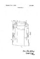
- FIG. 2 is a view, also in longitudinal section, showing the thrust vectoring nozzle aligned with the missile body and the fins folded down in the pre-launch condition, and
- FIG. 3 is a view in cross section to show one form of fin-erecting mechanism.
- a Wingless missile body indicated generally at 1 has a tail pipe 2, for discharge of the propulsion gases, which ends in a fixed efflux nozzle 3 of the convergent/divergent type.
- a fixed efflux nozzle 3 of the convergent/divergent type.
- Mounted around the throat 4 of the nozzle 3 is the fixed inner ball member 5 of a spherical bearing assembly 5, 6.
- the ring 6 is fitted within an annular housingmember 7 which also forms a mounting for both a control fin assembly, indicated generally at 8, and a thrust-deflecting outer nozzle 9.
- piston-and-cylinder type actuators 30 Mounted around the rear portion of the tail pipe 2 are a number of piston-and-cylinder type actuators 30, the pistons 10 of which are linked by connecting rod 11 to the housing member 7 whereby these actuators 30 are able to swivel the housing member 7, and with it the complete fin assembly and thrust-deflecting nozzle, upon the spherical bearing 5, 6.
- the arrangement must permit of controlled angular deflection of the fin assembly and outer nozzle universally in all directions with respect to the longitudinal axis of the missile. This can be achieved by means of two actuators, each of the double-acting differential pressure type, disposed from one another around the missile axis; but other arrangements are possible, sich as three single-acting actuators.
- a guidance head in the nose of the'missile seeks out the target and gives continuous signal data in regard to the bearing of the target from the missile.
- control signals are derived for application to the'servo-valves of the actuators for the purpose of continuously correcting the missile flight, to ensure interception of the target, by deflections of the fin and deflector nozzle assembly.
- the angular deflections of the fin and deflector nozzle assembly take place about the geometrical centre 24 of the spherical bearing surfaces, which centre lies on the longitudinal axis 12 of the missile and is also the centre of the throat 4 of the fixed inner nozzle 3 substantially in the place where the throat is narrowest.
- the spherical bearing assembly incorporates a key 13 and a key slot 14 which co-operate to prevent rotation of the housing member 7 about the longitudinal axis of the missile body.
- the key slot 14 is formed in the fixed ball 5 and extends parallel to the missile axis, whereby the member 7 is able to swivel in one particular plane containing the longitudinal axis of the missile by travel to and fro of the key 13, associated with the bearing ring 6, along the slot 14.
- the key 13 has a shank 25 of short cylindrical form which is rotatable in a circular hole 26 in the bearing ring 6 about an axis 27 that passes through the bearing centre 24 and lies at right angles to the longitudinal axis 12 of the missile when the fin and outer nozzle assembly is undeflected.
- the fin assembly includes a Z-shaped mounting ring 6 which is carried by a ball bearing 15 around the housing member 7 so that it can spin freely about the axis 28 of the deflector nozzle 9.
- the axis 28 is in alignment with the missile axis 12 when the nozzle is undeflected; and at other times it intersects the axis 12 at the centre 24.
- the stabilising and control fins 17 are hingedly mounted on the Z-ring 16 by means of hinge pins 29 parallel to the axis 28. The fins 17 are thus able to fold down flat around the nozzle assembly, about the hinge pins 29, when the missile is not in flight; FIGS. 2 and 3 show the fins folded down, the tail portion of the missile casing being recessed somewhat, as at 31, to accomodate them.
- the missile Before launching, the missile is contained, or the tail portion at least is contained, within a launch tube, the deflecting nozzle 9 being aligned with the missile body and the fins folded down as in FIG. 2.
- the fins are erected automatically. This can be achieved in various ways, one of which is to provide an additional ring upon the Z-ring 16 which is spring-loaded to move through a certain angular distance relatively to the Z-ring 16 and has coupled to it short lever arms that are connected to the fins.
- FIG. 3 Another arrangement is shown in FIG. 3, in which springs are coupled to the fin lever arms 19 by means of links 21'.
- a locking ring 22 is provided around the tail pipe 2 forward-of the fin and nozzle assembly to engage the forward face of the housing member 7 and prevent swivelling of the member 7 during the launch phase. The puspose of this is to prevent the missile turning toward the aircraft that launches it. When the missile is clear of the launching aircraft, the locking ring 22 is automatically released.
- the deflecting outer nozzle 9 has a short divergent mouth portion 32 which is a rearward continuation of the fixed divergent inner nozzle 3 when the outer nozzle 9 is undeflected. Forward of the mouth 32 the outer nozzle becomes of considerably greater diameter, with its largest internal diameter; as seen at 33, giving a wide annular clearance space 34 between the inner wall of the outer nozzle 9 and the fixed inner nozzle 3. This permits the outer nozzle 9 to deflect to an appreciable angle relatively to the fixed inner nozzle 3 before the rim 35 of the fixed nozzle encounters the wall 33 of the outer nozzle.
- the inner wall of the outer nozzle 9 takes the form of a part-spherical annular dome 36 having its geometrical centre coincident with the swivel centre 24.
- This dome surface 36 fits close up to a mating part-spherical surface 37 formed as an external annulus around the exit of the divergent mouth of the inner fixed nozzle 3.
- the surface 37 is also generated about the same centre 24, so that as the outer nozzle 9 deflects angularly the surfaces 36 and 37 remain in mating proximity around one side of the nozzle opening, as can be seen in FIG. 1.
- the missile is, as already indicated, carried by an aircraft in a launch tube with its thrust vectoring nozzle undeflected and locked and its fins folded down.
- the launch tube may be a simple tube of resin-bonded paper with an internal choke ring, like a piston ring, at or near the rear end.
- An advantage of such a launch tube is that is provides thermal insulation, both by reason of the tube material itself and because of the air gap between the tube and the missile, which will keep the missile systems at more or less the same temperature for a number of hours in 'flight.
- dome deflector nozzle gives efficient thrust vectoring with a very low thrust loss.
- aerodynamic roll perturbations from the fins during control manoeuvres are isolated from the missile body by the fact that the fins are able to spin freely on the bearing 15. This avoids the erratic twitching behaviour during heading changes which has been a characteristic of previous missiles but which tends to upset the operation of the guidance head.
- An advantage of the spherical bearing assembly is that it acts as a flame trap, preventing the flame and hot gases of the nozzle efflux from passing forward beyond the space 34 between the inner and outer nozzles.
- the dome deflector surface 36 and co-operating fixed surface 37 on the inner nozzle 3 also provide a partial flame seal.
- the invention may be carried into practice by arrangements other than that described and illustrated and in particular, the spherical bearing assembly may be replaced by another form of universal swivel mounting, such as a gimbal mounting. In this case, a separate flame and gas seal needs to be provided; one possibility is the fitting of a sealing flexible diaphragm.
- a steering and propulsion system for an aerial or space vehicle such as a guided missile, comprising a tail nozzle through which propulsive gas effluent issues which nozzle is dirigible to give steering by the vectored thrust principle, the nozzle being mounted to swivel in all directions about a chosen swivel centre point located forward of the nozzle exit, and wherein the dirigible nozzle has a rearwardly convergent portion, aft of the swivel point, leading up to the nozzle exit mouth, the internal wall of this convergent portion, which serves to deflect the effluent gases when the nozzle is moved angularly out of the straight ahead positionabout its swivel point, is both annular and domed being formed as a part-spherical surface and having the swivel point as its geometrical centre, and there is provided a set of aerodynamic control fins to stabilize the vehicle, said fins being mounted on the dirigible nozzle so as to deflect angularly with it.
- a system according to claim 2, wherein the aforesaid rim of the fixed inner nozzle comprises an annular surface that is part-spherical, to match the domed partspherical surface of the dirigible nozzle, and likewise has the swivel point as its geometrical centre.
- the spherical bearing assembly comprises a key and co-operating key-way arranged to permitangular deflection of the dirigible nozzle about the swivel point in two planes at right angles to one another while preventing rotation about the fore and aft axis.
Landscapes
- Engineering & Computer Science (AREA)
- Chemical & Material Sciences (AREA)
- Combustion & Propulsion (AREA)
- Mechanical Engineering (AREA)
- General Engineering & Computer Science (AREA)
- Aiming, Guidance, Guns With A Light Source, Armor, Camouflage, And Targets (AREA)
Applications Claiming Priority (1)
| Application Number | Priority Date | Filing Date | Title |
|---|---|---|---|
| GB322570 | 1970-04-30 |
Publications (1)
| Publication Number | Publication Date |
|---|---|
| US3764091A true US3764091A (en) | 1973-10-09 |
Family
ID=9754332
Family Applications (1)
| Application Number | Title | Priority Date | Filing Date |
|---|---|---|---|
| US00141364A Expired - Lifetime US3764091A (en) | 1970-04-30 | 1971-04-30 | Improvements in or relating to control systems |
Country Status (4)
| Country | Link |
|---|---|
| US (1) | US3764091A (OSRAM) |
| FR (1) | FR2165695B1 (OSRAM) |
| GB (1) | GB1342342A (OSRAM) |
| SE (1) | SE377719C (OSRAM) |
Cited By (15)
| Publication number | Priority date | Publication date | Assignee | Title |
|---|---|---|---|---|
| DE2743371A1 (de) * | 1976-10-04 | 1978-04-13 | Ford Aerospace & Communication | Kombiniertes heissgas-servosteuersystem fuer ruder und rueckstoss bei flugkoerpern |
| US4274610A (en) * | 1978-07-14 | 1981-06-23 | General Dynamics, Pomona Division | Jet tab control mechanism for thrust vector control |
| US4561357A (en) * | 1982-09-15 | 1985-12-31 | General Dynamics Pomona Division | Steering mechanism for an explosively fired projectile |
| USH159H (en) | 1984-12-17 | 1986-11-04 | The United States Of America As Represented By The Secretary Of The Navy | Shaped trajectory cruise missile launch mode |
| US4892268A (en) * | 1988-08-05 | 1990-01-09 | A.R.I.S.S.P.A. | Propulsion, monitoring and control unit particularly for ballistic objects |
| US5125596A (en) * | 1989-05-23 | 1992-06-30 | Cavalleri Robert J | Fluid shielded movable strut for missile and rocket thrust vector control |
| US6250584B1 (en) | 1999-10-18 | 2001-06-26 | Hr Textron, Inc. | Missile fin locking mechanism |
| US6568628B1 (en) * | 1977-07-28 | 2003-05-27 | Raytheon Company | Shipboard point defense system and elements therefor |
| US20040011920A1 (en) * | 2000-07-03 | 2004-01-22 | Stig Johnsson | Fin-stabilized guidable missile |
| US20050224631A1 (en) * | 2004-03-05 | 2005-10-13 | The Boeing Company | Mortar shell ring tail and associated method |
| US7125058B2 (en) | 2003-10-27 | 2006-10-24 | Hr Textron, Inc. | Locking device with solenoid release pin |
| US20070007383A1 (en) * | 2005-02-11 | 2007-01-11 | Hsu William W | Techniques for controlling a fin with unlimited adjustment and no backlash |
| US20110094372A1 (en) * | 2009-10-22 | 2011-04-28 | Honeywell International Inc. | Steerable projectile charging system |
| US20130311010A1 (en) * | 2011-01-26 | 2013-11-21 | Astrium Sas | Method and system for piloting a flying craft with rear propulsion unit |
| CN104085526A (zh) * | 2014-06-25 | 2014-10-08 | 西北工业大学 | 一种实现巡飞器翼身连接、固定、锁死、解锁的一体化结构 |
Families Citing this family (2)
| Publication number | Priority date | Publication date | Assignee | Title |
|---|---|---|---|---|
| JP3710099B2 (ja) * | 1995-03-31 | 2005-10-26 | 株式会社アイ・エイチ・アイ・エアロスペース | ジェッタベータ |
| CN102363444B (zh) * | 2011-09-09 | 2013-07-17 | 江西洪都航空工业集团有限责任公司 | 一种尾翼横向折叠机构 |
Citations (4)
| Publication number | Priority date | Publication date | Assignee | Title |
|---|---|---|---|---|
| US3003312A (en) * | 1957-08-19 | 1961-10-10 | Thompson Ramo Wooldridge Inc | Exhaust nozzle for jet engines |
| US3102390A (en) * | 1960-03-09 | 1963-09-03 | Fredrick R Barnet | Jetevator system design |
| US3210935A (en) * | 1959-09-23 | 1965-10-12 | Lyman C Fisher | Jetevator for missile control |
| US3438581A (en) * | 1967-02-06 | 1969-04-15 | Continental Aviat & Eng Corp | Internally gimbaled vectoring nozzle |
Family Cites Families (5)
| Publication number | Priority date | Publication date | Assignee | Title |
|---|---|---|---|---|
| US2780059A (en) * | 1955-11-29 | 1957-02-05 | Willy A Fiedler | Jet direction control device |
| US3069852A (en) * | 1959-10-27 | 1962-12-25 | Goodyear Aircraft Corp | Thrust vectoring apparatus |
| US3210936A (en) * | 1959-12-10 | 1965-10-12 | Lyman C Fisher | Jetevator for missile control |
| US3233834A (en) * | 1962-07-09 | 1966-02-08 | Aerojet General Co | Sealing means for rocket nozzle and jet deflection device mounted thereon |
| US3285520A (en) * | 1964-11-10 | 1966-11-15 | Glenn A Johnson | Eccentrically pivoted jetevator with conformable seal |
-
1971
- 1971-04-29 SE SE7105581A patent/SE377719C/xx unknown
- 1971-04-29 FR FR7115337A patent/FR2165695B1/fr not_active Expired
- 1971-04-30 US US00141364A patent/US3764091A/en not_active Expired - Lifetime
- 1971-04-30 GB GB322570A patent/GB1342342A/en not_active Expired
Patent Citations (4)
| Publication number | Priority date | Publication date | Assignee | Title |
|---|---|---|---|---|
| US3003312A (en) * | 1957-08-19 | 1961-10-10 | Thompson Ramo Wooldridge Inc | Exhaust nozzle for jet engines |
| US3210935A (en) * | 1959-09-23 | 1965-10-12 | Lyman C Fisher | Jetevator for missile control |
| US3102390A (en) * | 1960-03-09 | 1963-09-03 | Fredrick R Barnet | Jetevator system design |
| US3438581A (en) * | 1967-02-06 | 1969-04-15 | Continental Aviat & Eng Corp | Internally gimbaled vectoring nozzle |
Cited By (21)
| Publication number | Priority date | Publication date | Assignee | Title |
|---|---|---|---|---|
| DE2743371A1 (de) * | 1976-10-04 | 1978-04-13 | Ford Aerospace & Communication | Kombiniertes heissgas-servosteuersystem fuer ruder und rueckstoss bei flugkoerpern |
| US6568628B1 (en) * | 1977-07-28 | 2003-05-27 | Raytheon Company | Shipboard point defense system and elements therefor |
| US4274610A (en) * | 1978-07-14 | 1981-06-23 | General Dynamics, Pomona Division | Jet tab control mechanism for thrust vector control |
| US4561357A (en) * | 1982-09-15 | 1985-12-31 | General Dynamics Pomona Division | Steering mechanism for an explosively fired projectile |
| USH159H (en) | 1984-12-17 | 1986-11-04 | The United States Of America As Represented By The Secretary Of The Navy | Shaped trajectory cruise missile launch mode |
| US4892268A (en) * | 1988-08-05 | 1990-01-09 | A.R.I.S.S.P.A. | Propulsion, monitoring and control unit particularly for ballistic objects |
| US5125596A (en) * | 1989-05-23 | 1992-06-30 | Cavalleri Robert J | Fluid shielded movable strut for missile and rocket thrust vector control |
| US6250584B1 (en) | 1999-10-18 | 2001-06-26 | Hr Textron, Inc. | Missile fin locking mechanism |
| US20040011920A1 (en) * | 2000-07-03 | 2004-01-22 | Stig Johnsson | Fin-stabilized guidable missile |
| US6796525B2 (en) * | 2000-07-03 | 2004-09-28 | Bofors Defence Ab | Fin-stabilized guidable missile |
| US7125058B2 (en) | 2003-10-27 | 2006-10-24 | Hr Textron, Inc. | Locking device with solenoid release pin |
| US20050224631A1 (en) * | 2004-03-05 | 2005-10-13 | The Boeing Company | Mortar shell ring tail and associated method |
| US7262394B2 (en) * | 2004-03-05 | 2007-08-28 | The Boeing Company | Mortar shell ring tail and associated method |
| US20070007383A1 (en) * | 2005-02-11 | 2007-01-11 | Hsu William W | Techniques for controlling a fin with unlimited adjustment and no backlash |
| US7195197B2 (en) | 2005-02-11 | 2007-03-27 | Hr Textron, Inc. | Techniques for controlling a fin with unlimited adjustment and no backlash |
| US20110094372A1 (en) * | 2009-10-22 | 2011-04-28 | Honeywell International Inc. | Steerable projectile charging system |
| US8362408B2 (en) | 2009-10-22 | 2013-01-29 | Honeywell International Inc. | Steerable projectile charging system |
| US20130311010A1 (en) * | 2011-01-26 | 2013-11-21 | Astrium Sas | Method and system for piloting a flying craft with rear propulsion unit |
| US8825231B2 (en) * | 2011-01-26 | 2014-09-02 | Astrium Sas | Method and system for piloting a flying craft with rear propulsion unit |
| CN104085526A (zh) * | 2014-06-25 | 2014-10-08 | 西北工业大学 | 一种实现巡飞器翼身连接、固定、锁死、解锁的一体化结构 |
| CN104085526B (zh) * | 2014-06-25 | 2016-03-30 | 西北工业大学 | 一种实现巡飞器翼身连接、固定、锁死、解锁的一体化结构 |
Also Published As
| Publication number | Publication date |
|---|---|
| FR2165695A1 (OSRAM) | 1973-08-10 |
| GB1342342A (en) | 1974-01-03 |
| SE377719C (sv) | 1978-11-20 |
| SE377719B (OSRAM) | 1975-07-21 |
| FR2165695B1 (OSRAM) | 1976-02-06 |
Similar Documents
| Publication | Publication Date | Title |
|---|---|---|
| US3764091A (en) | Improvements in or relating to control systems | |
| US4274610A (en) | Jet tab control mechanism for thrust vector control | |
| EP0928269B1 (en) | Vehicle rotation and control mechanism | |
| US8674278B2 (en) | Control of projectiles or the like | |
| US4967982A (en) | Lateral thruster for missiles | |
| EP0076271A1 (en) | DIRECTIONAL CONTROL DEVICE FOR MISSILES MOVING IN AIR OR IN WATER. | |
| US20100275576A1 (en) | System and method for maneuvering rockets | |
| US4560121A (en) | Stabilization of automotive vehicle | |
| EP3668786B1 (en) | Actuating system | |
| US5129604A (en) | Lateral thrust assembly for missiles | |
| US11768062B2 (en) | Guided missile with at least one engine for producing forward thrust | |
| US4044970A (en) | Integrated thrust vector aerodynamic control surface | |
| US3000597A (en) | Rocket-propelled missile | |
| US5398887A (en) | Finless aerodynamic control system | |
| US2969017A (en) | Stabilizers for jet-propelled vehicles | |
| RU2094748C1 (ru) | Ракета | |
| US3276376A (en) | Thrust and direction control apparatus | |
| US3637167A (en) | Missile steering system | |
| RU2166727C1 (ru) | Способ управления вращающимся снарядом и управляемый снаряд | |
| US2879955A (en) | Airborne bodies and in particular self propelled missiles | |
| US4433606A (en) | Tandem rocket launcher | |
| US3854678A (en) | Rotary valve jet flap control system | |
| EP0060726A2 (en) | Gas thruster systems | |
| US2919544A (en) | Steering mechanism for jet propelled craft | |
| RU2111446C1 (ru) | Ракета, выполненная по аэродинамической схеме "утка" |
Legal Events
| Date | Code | Title | Description |
|---|---|---|---|
| AS | Assignment |
Owner name: BRITISH AEROSPACE PUBLIC LIMITED COMPANY, DISTRICT Free format text: CHANGE OF NAME;ASSIGNOR:BRITISH AEROSPACE LIMITED;REEL/FRAME:004080/0820 Effective date: 19820106 Owner name: BRITISH AEROSPACE PUBLIC LIMITED COMPANY Free format text: CHANGE OF NAME;ASSIGNOR:BRITISH AEROSPACE LIMITED;REEL/FRAME:004080/0820 Effective date: 19820106 |
|
| AS | Assignment |
Owner name: BRITISH AEROSPACE, ENGLAND Free format text: ASSIGNOR HEREBY ASSIGNS NUNC PRO TUNC AS OF NOV. 22, 1978, THE ENTIRE INTEREST TO SAID ASSIGNEE TO SAID ASSIGNEE IN SAID PATENTS AND PATENT APPLICATIONS;ASSIGNOR:HAWKER SIDDELEY DYNAMICS LIMITED;REEL/FRAME:003949/0771 Effective date: 19811218 Owner name: BRITISH AEROSPACE, BROOKLANDS RD., WEYBRIDGE SURRE Free format text: ASSIGNOR HEREBY ASSIGNS NUNC PRO TUNC AS OF NOV. 22, 1978, THE ENTIRE INTEREST TO SAID ASSIGNEE TO SAID ASSIGNEE IN SAID PATENTS AND PATENT APPLICATIONS;ASSIGNOR:HAWKER SIDDELEY DYNAMICS LIMITED;REEL/FRAME:003949/0771 Effective date: 19811218 |