EP0060726A2 - Gas thruster systems - Google Patents
Gas thruster systems Download PDFInfo
- Publication number
- EP0060726A2 EP0060726A2 EP82301351A EP82301351A EP0060726A2 EP 0060726 A2 EP0060726 A2 EP 0060726A2 EP 82301351 A EP82301351 A EP 82301351A EP 82301351 A EP82301351 A EP 82301351A EP 0060726 A2 EP0060726 A2 EP 0060726A2
- Authority
- EP
- European Patent Office
- Prior art keywords
- gas
- nozzles
- pair
- valve means
- thruster system
- Prior art date
- Legal status (The legal status is an assumption and is not a legal conclusion. Google has not performed a legal analysis and makes no representation as to the accuracy of the status listed.)
- Withdrawn
Links
Images
Classifications
-
- F—MECHANICAL ENGINEERING; LIGHTING; HEATING; WEAPONS; BLASTING
- F42—AMMUNITION; BLASTING
- F42B—EXPLOSIVE CHARGES, e.g. FOR BLASTING, FIREWORKS, AMMUNITION
- F42B10/00—Means for influencing, e.g. improving, the aerodynamic properties of projectiles or missiles; Arrangements on projectiles or missiles for stabilising, steering, range-reducing, range-increasing or fall-retarding
- F42B10/60—Steering arrangements
- F42B10/66—Steering by varying intensity or direction of thrust
- F42B10/663—Steering by varying intensity or direction of thrust using a plurality of transversally acting auxiliary nozzles, which are opened or closed by valves
-
- F—MECHANICAL ENGINEERING; LIGHTING; HEATING; WEAPONS; BLASTING
- F02—COMBUSTION ENGINES; HOT-GAS OR COMBUSTION-PRODUCT ENGINE PLANTS
- F02K—JET-PROPULSION PLANTS
- F02K9/00—Rocket-engine plants, i.e. plants carrying both fuel and oxidant therefor; Control thereof
- F02K9/80—Rocket-engine plants, i.e. plants carrying both fuel and oxidant therefor; Control thereof characterised by thrust or thrust vector control
- F02K9/88—Rocket-engine plants, i.e. plants carrying both fuel and oxidant therefor; Control thereof characterised by thrust or thrust vector control using auxiliary rocket nozzles
Definitions
- U.S. Patent No. 4,017,040 discloses a steerable rocket motor apparatus adapted to tow a load, such as an aircraft ejection seat, fastened to the rocket apparatus by means of a tow line.
- the rocket apparatus is caused to fly a computed trajectory by controlling the thrust of opposed pairs of rocket nozzles, a valve member being provided for proportioning the escape of high pressure gas between each pair of opposed nozzles.
- the valve member is formed with regions of differing diameter at its centre length whereby opposed surfaces of differing face area are provided.
Abstract
A gas thruster system particularly suited for use in controlling the flight of an aerial projectile, has self-centering valve means controlling the exhaust of gas from a pair of oppositely directed exhaust nozzles. Actuating means, which may comprise a pair of solenoids, are adapted for cooperation with the valve means and, in operation, shift the valve means to either side of a null central position towards closing one or the other of the pair of nozzles to provide differential gas flow from the pair of nozzles whilst maintaining a substantially constant area vent from a gas source.
Description
- THIS INVENTION relates to gas thruster systems and is particularly, but not exclusively, concerned with a gas thruster system suited for use in controlling the flight of a projectile propelled from a gun.
- It is known to steer rockets along a night path by controlled exhaust of gas from opposed nozzles. For example, U.S. Patent No. 4,017,040 discloses a steerable rocket motor apparatus adapted to tow a load, such as an aircraft ejection seat, fastened to the rocket apparatus by means of a tow line. The rocket apparatus is caused to fly a computed trajectory by controlling the thrust of opposed pairs of rocket nozzles, a valve member being provided for proportioning the escape of high pressure gas between each pair of opposed nozzles. In the detailed disclosure of U.S. 4,017,040 the valve member is formed with regions of differing diameter at its centre length whereby opposed surfaces of differing face area are provided. In operation, one of these surface areas is constantly exposed to combustion chamber pressure which tends to move the valve member towards closing the nozzle at the opposite end of the valve member. This pressure is balanced to move the valve member to a null centre position in which there is equal thrust from each nozzle, or is overcome to move the valve member towards closing the opposite nozzle, by pressure applied to an opposed surface area of the valve member under the control of an electrically actuated spool valve.
- A disadvantage of this arrangement is that the valve member is not self-centering and, if the valve member control loop is not actuated before commencement of rocket motor firing, the valve member is biassed to close one of the nozzles of the pair of opposed nozzles with which it is associated so that unidirectional thrust is applied to the rocket motor apparatus by gas escaping from the opposite nozzle, and the apparatus does not fly along a straight line path. After actuation of the valve member control loop, the valve member hunts before finding a null centre position between its opposed pair of nozzles to provide equal thrust from each nozzle and cause the apparatus to fly along a straight line path. Such a system is not satisfactory for controlling the flight of a projectile that is adapted to be propelled from a gun.
- It is an object of the invention to provide a gas thruster system which is particularly suited for use in controlling the flight of an aerial projectile, and which has a high rate of response to control signals input to the system to produce thrust changes.
- It is a further object of the invention to provide a gas thruster system which is devoid of pressure control valves.
- Another object of the invention is to provide a gas thruster system combining low cost and minimum complexity with high reliability and rugged construction.
- According to the invention a gas thruster system comprises a gas source, vent means for supplying gas from the gas source to at least one pair of oppositely directed exhaust nozzles, valve means for controlling the discharge of gas from each pair of nozzles, means biassing each control valve means towards a null central position between its associated pair of nozzles, and actuating means for shifting each control valve means to either side of the null central position-towards closing one or the other of said pair of nozzles and thereby to provide differential gas flow from said pair of nozzles whilst maintaining a substantially constant area vent from the gas source.
- Means for centering each control valve means between its associated pair of nozzles may comprise a pair of opposing compression springs acting between the control valve means and opposed interior faces of a gas thruster body portion.-The actuating means may comprise one or more solenoids co-operating with valve elements adapted for controlling the discharge of gas from both nozzles of a pair of oppositely directed nozzles.
- In an embodiment of the invention a single valve element comprising a double ended poppet valve extends between an opposed pair- of nozzles and is arranged for reciprocal movement by a pair of solenoids.
- The gas source may be provided by gas generator means comprising a solid propellent charge in communication with a combustion chamber into which an igniter vents to ignite the solid propellent charge which burns to produce hot gas.
- A gas thruster system in accordance with the present invention is particularly suited for use in controlling the flight of a small calibre aerial projectile and comprises a gas source, vent means for supplying gas from said gas source to at least two pairs of oppositely directed exhaust nozzles arranged normal to each other to provide lateral forces for control of pitch and yaw, valve means for controlling the discharge of gas from each pair of nozzles, spring means biassing each control valve means towards a null central position between its associated pair of nozzles, and solenoid means adapted for shifting each control valve means to either side of the null central position towards closing one or the other of said pair of nozzles and thereby to provide differential gas flow from said pair of nozzles whilst maintaining substantially constant area vent from said gas source.
- Roll control may be provided by two pairs of oppositely directed exhaust nozzles arranged symmetrically of and parallel to a radial plane passing through the longitudinal axis of the aerial projectile, and these two pairs of nozzles may also be used to provide the lateral thrust forces for control of either pitch or yaw.
- The invention will now be further described by way of example and with reference to the accompanying drawings, in which:-
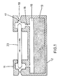
- Figure 1 illustrates the principal features of a gas thruster system in accordance with the present invention; and
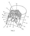
- Figure 2 shows a schematic fractional view of a gas thruster system in an embodiment of the invention.
- Referring to the drawings, a
gas thruster system 10 includes athruster body 11 and a gas source comprised by agas generator 12 which together are adapted to the profile of an associated aerial body, such as a projectile (not shown) which is adapted to be propelled from a gun. Thegas generator 12 comprises apropellent chamber 13 filled with an appropriatesolid propellent charge 14 which is in communication with acombustion chamber 15 into which an igniter (not shown) vents to ignite thesolid propellent charge 14 which burns to produce hot gas. Thecombustion chamber 15 connects by way ofducts 16 andorifices 17 with pairs of oppositely directedexhaust nozzles 18, which in the embodiment of Figure 2 comprise onepair 19 in one radial plane of thebody 11 and twoparallel pairs 20, 20a arranged symmetrically of another radial plane disposed normal to the radial plane in which the pair ofnozzles 19 lies. - The flow axis of the two nozzles of each pair of
nozzles poppet valve 23 and a pair of theorifices 17. Each of theorifices 17 is positioned so as to form an entry to thethroat region 21 of one of thenozzles 18 and connects this with asmall chamber 22 into which one or more of thecombustion gas ducts 16 enters. Thevalve 23 is arranged to slide, in a leakproof manner, within thethruster body 11 and to be co-operable with the twoorifices 17. Thevalve 23 extends through asolenoid arrangement 24 which comprises a pair ofsolenoids 25 mounted back to back and positioned centrally within thethruster body 11. Thepoppet valve 23 is retained as part of thesolenoid arrangement 24 by a pair ofcirclips 26 located on its surface outboard of the twosolenoids 25 and is urged towards a null central position between its associated pair of nozzles byopposing compression springs 27 exerting a force between thecirclips 26 and opposed interior surfaces of thethruster body 11. The heads of the.valves 23 are suitably shaped relative to theorifices 17 so as to provide a constant, or substantially constant, total area of vent from thecombustion chamber 15 of thegas generator 12 irrespective of the operating position of thevalve 23. - In operation of the invention with the
gas thruster system 10 attached to an aerial projectile (not shown),, in the system-off condition, prior to firing of the projectile and ignition of thepropellent charge 14, eachvalve 23 is centered between its associated pair of nozzles by the action of thecompression spring 27. On firing the projectile and ignition of thepropellent charge 14 pressurised combustion gases issue from thecombustion chamber 15 by way of theducts 16,chambers 22 and theorifices 17, to discharge equally and oppositely from thenozzles 18 of each pair ofnozzles - When sensing and signalling means (not shown and forming no part of this invention) require a course correction to be made the
appropriate solenoid 25 of the one or twosolenoid arrangements 24 is energised, according to which control axis it is necessary to activate, i.e. yaw, pitch or roll. Energisation of asolenoid 25 causes thevalve member 23 to move towards oneorifice 17 so as to reduce its flow area and equally to move away from thecompanion orifice 17 which increases the flow area of this correspondingly, whereby the flow rate from the twoopposing nozzles 18 becomes unequal while maintaining a constant, or substantially constant, total flow rate. Translation of the difference in thrust thus created across thethruster body 11 from the pair of nozzles, say 19, causes the projectile to rotate about its centre of gravity in, say, the pitching plane, or translate towards a correcting course. - Similarly, if the two pairs of
nozzles 20, 20a are assumed then to be in the yawing plane and their corresponding solenoids are energised to move theirpoppet valves 23 in the same direction and to the same extent, then directional correction of the flight of the aerial body is obtained in this plane. Movement in roll is obtained by way of these two pairs ofnozzles 20, 20a when their oppositely directed solenoids are energised to move their poppet valves 23-in opposite directions whereby the oppositely directed discharges become offset and cause the aerial body (not shown) to roll. - In all directional control modes and irrespective of their rates of operation gas thruster systems according to the invention maintain constant, or substantially constant, gas flow rate by providing an effectively constant area vent from a gas source such as a simple solid propellent gas generator without need for the use of pressure regulating valves and associated components.
Claims (8)
1. A gas thruster system comprising a gas source, vent means for supplying gas from the gas source to at least one pair of oppositely directed exhaust nozzles, valve means for controlling the discharge of gas from each pair of nozzles, means biassing each control valve means towards a null central position between its associated pair of nozzles, and actuating means for shifting each control valve means to either side of the null position towards closing one or the other of said pair of nozzles and thereby to provide differential gas flow from the pair of nozzles whilst maintaining a substantially constant area vent from the gas source.
2. A gas thruster system as claimed in Claim 1, wherein said actuating means comprises one or more solenoids.
3. A gas thruster system as claimed in Claim 1 or Claim 2, wherein said biassing means comprises a pair of opposed compression springs acting between said control valve means and interior faces of a gas thruster body portion.
4. A gas thruster system as claimed in any preceding Claim, wherein each said control valve means comprises a single valve element adapted for controlling the discharge of gas from both nozzles of said at least one pair of oppositely directed nozzles.
5. A gas thruster system as claimed in Claim 4, wherein the single valve element comprises a double-ended poppet valve.
6. A gas thruster system as claimed in any preceding Claim, wherein the gas source is provided by gas generator means comprising a solid propellent charge in communication with a combustion chamber into which an igniter vents to ignite the solid propellent charge which burns to produce hot gas.
7. A small calibre aerial projectile including a gas thruster system comprising a gas source, vent means for supplying gas from said gas source to at least two pairs of oppositely directed exhaust nozzles arranged normal to each other to provide lateral forces for control of pitch and yaw, valve means for controlling the discharge of gas from each pair of nozzles, spring means biassing each control valve means towards a null central position between its associated pair of nozzles,. and solenoid means adapted for shifting each control valve means to either side of the null position towards closing one or the other of said pair of nozzles and thereby to provide differential gas flow from said pair of nozzles whilst maintaining a substantially constant area vent from said gas source.
8. A small calibre aerial projectile as claimed in Claim 7, wherein two pairs of oppositely directed exhaust nozzles are arranged symmetrically of and parallel to a radial plane passing through the longitudinal axis of the aerial projectile to provide lateral thrust forces for roll control.
Applications Claiming Priority (2)
| Application Number | Priority Date | Filing Date | Title |
|---|---|---|---|
| GB8108361 | 1981-03-17 | ||
| GB8108361 | 1981-03-17 |
Publications (2)
| Publication Number | Publication Date |
|---|---|
| EP0060726A2 true EP0060726A2 (en) | 1982-09-22 |
| EP0060726A3 EP0060726A3 (en) | 1983-02-09 |
Family
ID=10520447
Family Applications (1)
| Application Number | Title | Priority Date | Filing Date |
|---|---|---|---|
| EP82301351A Withdrawn EP0060726A3 (en) | 1981-03-17 | 1982-03-16 | Gas thruster systems |
Country Status (1)
| Country | Link |
|---|---|
| EP (1) | EP0060726A3 (en) |
Cited By (9)
| Publication number | Priority date | Publication date | Assignee | Title |
|---|---|---|---|---|
| FR2538098A1 (en) * | 1982-12-17 | 1984-06-22 | Thomson Brandt | DEVICE FOR CONTROLLING LATERAL GAS JETS |
| EP0215185A1 (en) * | 1985-09-05 | 1987-03-25 | Rheinmetall GmbH | Steering block |
| WO1987004989A1 (en) * | 1986-02-21 | 1987-08-27 | Plessey Overseas Limited | Reaction jet control system |
| EP0244971A2 (en) * | 1986-05-09 | 1987-11-11 | LUCAS INDUSTRIES public limited company | Missile flight control system |
| EP0306140A1 (en) * | 1987-07-28 | 1989-03-08 | Morton Thiokol, Inc. | Ultralightweight high operating temperature structures |
| EP0542606A1 (en) * | 1991-11-15 | 1993-05-19 | Thomson-Brandt Armements | Hydraulicly blocked commanding device for auxiliary jets |
| EP0686824A1 (en) * | 1994-04-30 | 1995-12-13 | Daimler-Benz Aerospace Aktiengesellschaft | Thrust generating device |
| US8362408B2 (en) | 2009-10-22 | 2013-01-29 | Honeywell International Inc. | Steerable projectile charging system |
| FR2980265A1 (en) * | 2011-09-21 | 2013-03-22 | Mbda France | SYSTEM FOR STEERING A FLYING VEHICLE USING SIDEWALK PAIRS |
Citations (4)
| Publication number | Priority date | Publication date | Assignee | Title |
|---|---|---|---|---|
| US2613497A (en) * | 1947-04-01 | 1952-10-14 | Macdonald Gilmour Craig | Controllable rocket thrust device |
| US2974594A (en) * | 1958-08-14 | 1961-03-14 | Boehm Josef | Space vehicle attitude control system |
| US3726496A (en) * | 1971-08-04 | 1973-04-10 | Us Army | Tridirectional actuator |
| US4017040A (en) * | 1976-01-12 | 1977-04-12 | The United States Of America As Represented By The Secretary Of The Navy | Steerable extraction rocket |
-
1982
- 1982-03-16 EP EP82301351A patent/EP0060726A3/en not_active Withdrawn
Patent Citations (4)
| Publication number | Priority date | Publication date | Assignee | Title |
|---|---|---|---|---|
| US2613497A (en) * | 1947-04-01 | 1952-10-14 | Macdonald Gilmour Craig | Controllable rocket thrust device |
| US2974594A (en) * | 1958-08-14 | 1961-03-14 | Boehm Josef | Space vehicle attitude control system |
| US3726496A (en) * | 1971-08-04 | 1973-04-10 | Us Army | Tridirectional actuator |
| US4017040A (en) * | 1976-01-12 | 1977-04-12 | The United States Of America As Represented By The Secretary Of The Navy | Steerable extraction rocket |
Cited By (20)
| Publication number | Priority date | Publication date | Assignee | Title |
|---|---|---|---|---|
| EP0112755A2 (en) * | 1982-12-17 | 1984-07-04 | Thomson-Brandt Armements | Control device operating by lateral gas jet action |
| EP0112755A3 (en) * | 1982-12-17 | 1984-09-26 | Brandt Armements Societe Anonyme De Nationalite Francaise | Control device operating by lateral gas jet action |
| JPS59192851A (en) * | 1982-12-17 | 1984-11-01 | ブラント・アルムマン | Lateral gas injection guide apparatus |
| US4632336A (en) * | 1982-12-17 | 1986-12-30 | Brandt-Armements | Lateral gas jet piloting device |
| FR2538098A1 (en) * | 1982-12-17 | 1984-06-22 | Thomson Brandt | DEVICE FOR CONTROLLING LATERAL GAS JETS |
| EP0215185A1 (en) * | 1985-09-05 | 1987-03-25 | Rheinmetall GmbH | Steering block |
| US4726544A (en) * | 1985-09-05 | 1988-02-23 | Rheinmetall Gmbh | Projectile steering block |
| US4856734A (en) * | 1986-02-21 | 1989-08-15 | Plessey Overseas Limited | Reaction jet control system |
| WO1987004989A1 (en) * | 1986-02-21 | 1987-08-27 | Plessey Overseas Limited | Reaction jet control system |
| EP0244971A2 (en) * | 1986-05-09 | 1987-11-11 | LUCAS INDUSTRIES public limited company | Missile flight control system |
| EP0244971A3 (en) * | 1986-05-09 | 1988-04-27 | LUCAS INDUSTRIES public limited company | Missile flight control system |
| EP0306140A1 (en) * | 1987-07-28 | 1989-03-08 | Morton Thiokol, Inc. | Ultralightweight high operating temperature structures |
| EP0542606A1 (en) * | 1991-11-15 | 1993-05-19 | Thomson-Brandt Armements | Hydraulicly blocked commanding device for auxiliary jets |
| FR2683861A1 (en) * | 1991-11-15 | 1993-05-21 | Thomson Brandt Armements | PNEUMATIC LOCK JET SWITCH. |
| EP0686824A1 (en) * | 1994-04-30 | 1995-12-13 | Daimler-Benz Aerospace Aktiengesellschaft | Thrust generating device |
| US8362408B2 (en) | 2009-10-22 | 2013-01-29 | Honeywell International Inc. | Steerable projectile charging system |
| FR2980265A1 (en) * | 2011-09-21 | 2013-03-22 | Mbda France | SYSTEM FOR STEERING A FLYING VEHICLE USING SIDEWALK PAIRS |
| EP2573504A1 (en) * | 2011-09-21 | 2013-03-27 | MBDA France | System for piloting an aircraft using pairs of lateral nozzles |
| WO2013041784A1 (en) * | 2011-09-21 | 2013-03-28 | Mbda France | System for steering a flying object using pairs of lateral nozzles |
| US9212880B2 (en) | 2011-09-21 | 2015-12-15 | Mbda France | System for steering a flying object using pairs of lateral nozzles |
Also Published As
| Publication number | Publication date |
|---|---|
| EP0060726A3 (en) | 1983-02-09 |
Similar Documents
| Publication | Publication Date | Title |
|---|---|---|
| US4017040A (en) | Steerable extraction rocket | |
| EP0131573B1 (en) | Ram air combustion steering system for a guided missile | |
| US3094072A (en) | Aircraft, missiles, missile weapons systems, and space ships | |
| US4085909A (en) | Combined warm gas fin and reaction control servo | |
| DE3149735C2 (en) | ||
| US4560121A (en) | Stabilization of automotive vehicle | |
| US4537371A (en) | Small caliber guided projectile | |
| KR100186837B1 (en) | Lateral thrust assembly for missiles | |
| EP0060726A2 (en) | Gas thruster systems | |
| US3759466A (en) | Cruise control for non-ballistic missiles by a special arrangement of spoilers | |
| US3069846A (en) | Thrust device | |
| US3000597A (en) | Rocket-propelled missile | |
| US3764091A (en) | Improvements in or relating to control systems | |
| US8080771B2 (en) | Steering system and method for a guided flying apparatus | |
| EP0135500B1 (en) | Ram air steering system for a guided missile | |
| US3637167A (en) | Missile steering system | |
| US4763857A (en) | Guidance apparatus for projectiles | |
| US4295617A (en) | Selectable drag brakes for rocket range control | |
| US2977879A (en) | Rocket projectile | |
| US3489373A (en) | Missile configurations,controls and utilization techniques | |
| US6460801B1 (en) | Precision guidance system for aircraft launched bombs | |
| US4817377A (en) | Head end control and steering system: using a forward end maneuvering gas generator | |
| US6543717B1 (en) | Compact optimal and modulatable thrust device for controlling aerospace vehicles | |
| US3999381A (en) | Position control of jet pipe in missile attitude control system | |
| US3104613A (en) | Rocket projectile |
Legal Events
| Date | Code | Title | Description |
|---|---|---|---|
| PUAI | Public reference made under article 153(3) epc to a published international application that has entered the european phase |
Free format text: ORIGINAL CODE: 0009012 |
|
| AK | Designated contracting states |
Designated state(s): BE CH DE FR GB IT SE |
|
| PUAL | Search report despatched |
Free format text: ORIGINAL CODE: 0009013 |
|
| AK | Designated contracting states |
Designated state(s): BE CH DE FR GB IT LI SE |
|
| STAA | Information on the status of an ep patent application or granted ep patent |
Free format text: STATUS: THE APPLICATION IS DEEMED TO BE WITHDRAWN |
|
| 18D | Application deemed to be withdrawn |
Effective date: 19840119 |
|
| RIN1 | Information on inventor provided before grant (corrected) |
Inventor name: YOUNG, ROBERT WILLIAM |