US3763965A - Transfer vehicle for reels - Google Patents
Transfer vehicle for reels Download PDFInfo
- Publication number
- US3763965A US3763965A US00121394A US3763965DA US3763965A US 3763965 A US3763965 A US 3763965A US 00121394 A US00121394 A US 00121394A US 3763965D A US3763965D A US 3763965DA US 3763965 A US3763965 A US 3763965A
- Authority
- US
- United States
- Prior art keywords
- reel
- lift
- fork
- hydraulic cylinder
- transfer vehicle
- Prior art date
- Legal status (The legal status is an assumption and is not a legal conclusion. Google has not performed a legal analysis and makes no representation as to the accuracy of the status listed.)
- Expired - Lifetime
Links
Images

Classifications
-
- B—PERFORMING OPERATIONS; TRANSPORTING
- B62—LAND VEHICLES FOR TRAVELLING OTHERWISE THAN ON RAILS
- B62B—HAND-PROPELLED VEHICLES, e.g. HAND CARTS OR PERAMBULATORS; SLEDGES
- B62B3/00—Hand carts having more than one axis carrying transport wheels; Steering devices therefor; Equipment therefor
- B62B3/04—Hand carts having more than one axis carrying transport wheels; Steering devices therefor; Equipment therefor involving means for grappling or securing in place objects to be carried; Loading or unloading equipment
- B62B3/06—Hand carts having more than one axis carrying transport wheels; Steering devices therefor; Equipment therefor involving means for grappling or securing in place objects to be carried; Loading or unloading equipment for simply clearing the load from the ground
- B62B3/0618—Hand carts having more than one axis carrying transport wheels; Steering devices therefor; Equipment therefor involving means for grappling or securing in place objects to be carried; Loading or unloading equipment for simply clearing the load from the ground using fluid lifting mechanisms
-
- B—PERFORMING OPERATIONS; TRANSPORTING
- B60—VEHICLES IN GENERAL
- B60P—VEHICLES ADAPTED FOR LOAD TRANSPORTATION OR TO TRANSPORT, TO CARRY, OR TO COMPRISE SPECIAL LOADS OR OBJECTS
- B60P3/00—Vehicles adapted to transport, to carry or to comprise special loads or objects
- B60P3/035—Vehicles adapted to transport, to carry or to comprise special loads or objects for transporting reel units
-
- B—PERFORMING OPERATIONS; TRANSPORTING
- B65—CONVEYING; PACKING; STORING; HANDLING THIN OR FILAMENTARY MATERIAL
- B65H—HANDLING THIN OR FILAMENTARY MATERIAL, e.g. SHEETS, WEBS, CABLES
- B65H49/00—Unwinding or paying-out filamentary material; Supporting, storing or transporting packages from which filamentary material is to be withdrawn or paid-out
- B65H49/38—Skips, cages, racks, or containers, adapted solely for the transport or storage of bobbins, cops, or the like
Definitions
- a reel can be transferred directly to a storage space and need not be rolled over the floor.
- the reel can be lowered to the floor level and the vehicle then be pulled away and inserted under a new empty reel.
Abstract
A transfer vehicle for transferring reels to and from a winding machine. The vehicle is provided with a vertically movable liftfork and a hydraulic cylinder moving said lift-fork. The hydraulic cylinder is connected to a pressure accumulator which stores the energy of a full reel moving the lift-fork downwards and causes the lift-fork supporting an empty reel to move upwards due to the stored energy.
Description
United States Patent 1191 Riekkinen Oct. 9, 1973 TRANSFER VEHICLE FOR REELS 3,003,584 10/1961 Wiegand et a1 187/9 x [75] Inventor: Asko Sakari Riekkinen, FOREIGN PATENTS OR APPLICATIONS Klfkkonummh Finland 143,606 9/1951 Australia 280/4729 [73] Assignee: 0y Nokia Ab, Helsinki, Finland Primary Examiner-Even C. Blunk [22] led: 1971 Assistant Examiner-Merle F. Mafici [21] Appl. No.: 121,394 Attorney-Waters, Roditi, Schwartz & Nissen [30} Foreign Application Priority Data 57] ABSTRACT A transfer vehicle for transferring reels to and from a Mar. 6, 1970 Fmland ..618/70 winding machine. The vehicle is provided with a verti [52] US. Cl. 187/9, 280/4729 cally movable lift-fork and a hydraulic cylinder mov- [51] Int. Cl B66b 9/20 ng ai if -f r T hy ra li ylin er i c nn e [58] Field of Search 187/9, 17; o a p ur a m ato w h t r th n rgy f a 280/4728, 47,29 full reel moving the lift-fork downwards and causes the lift-fork supporting an empty reel to move up- [56] References Cited wards due to the stored energy.
UNITED STATES PATENTS 3 Claims, 2 Drawing Figures 2,737,303 3/1956 Held at al. 187/9 X 3,294,199 12/1966 Jarvik 187/17 X 2,854,245 9/1958 Manahan 280/4729 PAHNTED 9 E375 SHEET 2 UP 2 FIG.2
TRANSFER VEHICLE FOR REELS The invention concerns a transfer vehicle, especially for transferring reels to a winding machine and from the winding machine to a place of storage, the transfer vehicle being provided with a vertically movable liftfork for supporting a reel and with a pressure fluid operated hydraulic cylinder for movement of the lift-fork.
lh the cable industry there are particular problems connected with the transfer of cable reels. It is especially difficult and cumbersome to move the reels when they are full and 'heavy. The weight of the full reels requires great physical exertion from workers. Reels moved along the floor will cause damage thereto. It is desirable that the transfer of the reels can be effected by means of equipment that would spare musclepower and eliminate the risk of damage to the floor. In the cable industry the reels are usually positioned in the winding machines slightly above the floor level. The full reels are brought to ground level by being rolled down a sloping plane or even by dropping down the reels.
By means of the transfer vehicle according to the invention the said disadvantages will be eliminated. The transfer vehicle is characterized in that the vehicle is provided with a pressure accumulator connected to said hydraulic cylinder in such a way that the pressure fluid flows from the cylinder into the pressure accumulator when the lift-work is caused to descend under the weight of a full reel supported thereon and the pressure fluid stored in the pressure accumulator flows into the cylinder causing the lift-fork to raise when the lift-fork is supporting an empty reel.
The following advantages are derived from the use of a transfer vehicle according to the invention.
Lowering of the reel from the winding machine takes place not by dropping but at a controlled speed,-thus saving reels and floors. A reel can be transferred directly to a storage space and need not be rolled over the floor. The reel can be lowered to the floor level and the vehicle then be pulled away and inserted under a new empty reel.
The energy of a full reel is stored up and utilized to lift an empty reel to the level of the winding machine without musclepower or any outside source of energy being required therefor. I
The invention is described in closer detail in the following, with reference to the attached drawings, in which FIG. 1 is a front view partly in section of a transfer vehicle according to the invention, and
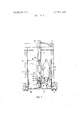
FIG. 2 is a side view in vertical cross-section of the transfer vehicle.
The transfer vehicle shown in the drawing comprises a frame 1 and a vertically movable lift-fork 2 consisting of a vertical plate 2a which, resting on wheels 3, can move vertically in vertical beamsof the frame 1, and of horizontal forks 2b fixed to the plate 2a for carrying a reel 18 (FIG. 2). The frame 1 is provided with wheels 4 on which the whole vehicle and the reel supported by the lift-fork are moved.
For vertical movement of the lift-fork there is provided a hydraulic cylinder 5 which is attached at its lower end to the frame 1 and at its upper end to the plate of the lift-fork. The cylinder is connected through a hose 7 and a throttle valve 8 to a pressure accumulator 6 which is attached to the frame.
To the upper cross-beam of the frame there is attached a cam mechanism comprising a lever 9 pivotably mounted in a bearing and a link 10 attached eccentrically to the shaft of the lever. The link 10 is attached to a shifting rod 11 which is vertically movably supported by the frame. To the lower part of the shifting rod there is fixed a stopper 12 as well as a locking lever 14 by means of a pivot pin 13. The locking lever is pressed by a spring 15 into the position shown in FIG. 2. A stopper 16 is also fixed to the plate 2a of the liftfork.
The hydraulic cylinder 5 and the hydraulic pressure accumulator 6 are filled with oil. The hydraulic pressure accumulator has a gas pressure which is so selected that the oil pressure produced thereby is able to lift the lift-fork 2 and an empty reel supported thereon into an upper position. The pushbar is designated with the reference numberal 17 and the reel to be transported by the vehicle with the reference numeral 18.
The vehicle operates as follows. The vehicle is positioned in front of the winding machine with the lift-fork 2 in its upper position. When a full reel is removed from the winding machine, the reel falls upon the forks 2b. The weight of a full reel is substantially greater than that of an empty reel, and the lift-fork 2 consequently begins to move downwards due to the weight of the full reel. The movement is retarded by means of the throttle valve 8, through which the oil in the cylinder 5 is forced to flow into the pressure accumulator 6. The downward movement of the lift-fork continues until the stopper 16 passes the locking lever 14 and rests against the stopper 12 on the shifting rod 11. At this stage the reel is approximately half an inch above the floor level. The reel can be transferred in this position to the desired place of storage.
When the reel should be lowered to the floor, the lever 9 is turned 180 to the left in FIG. 1 whereby the link 10 allows the shifting rod 11 and consequently also the lift-fork 2 to move downwards. due to the weight of the full reel so that the reel descends the remaining distance to the floor level. When the reel is supported on the floor, the downwards acting force in the fork 2 will cease. By means of the lever 9 and the link the lift-fork 2, however, can be displaced further downwards while it is still locked to the shifting rod 11 by means of the locking lever 14. The reel is thus entirely released from the fork 2, and the vehicle can be pulled out from under the reel. The vehicle is thereafter pushed underneath an empty reel. The lever 9 is turned to the right in FIG. 2 so that the shifting rod 11 and the liftfork 2 locked thereto rise lifting the reel from the floor level to a height of approximately half an inch. This is aided by the spring 15. The empty reel is now carried in front of the winding machine. When the locking lever 14 is depressed, the stopper 16 is released from the locking lever and the oil pressure in the pressure accumulator flows back to the hydraulic cylinder 5 which lifts the lift-fork 2 and the empty reel supported thereon into the upper position, from which the reel can be moved directly into the winding machine.
The figures and the description pertaining thereto are, naturally, intended merely to illustrate the idea of the invention. In practice, the construction, shape and material of the reel transfer vehicle may vary considerably within the scope of the claims.
What I claim is:
l. A transfer vehicle, especially for transferring empty reels to a winding machine and full reels from the winding machine to a place of storage, the transfer vehicle being provided with a vertically movable weight responsive lift-fork (2) for supporting a reel (18) and with a pressure fluid operated hydraulic cylinder (5) for movement of the lift-fork, characterized in that the vehicle is provided with a pressure accumulator (6) which is directly connected to said hydraulic cylinder (5) said accumulator pressurized to a degree so that it will automatically raise said lift-fork when supporting an empty reel by forcing fluid into said hydraulic cylinder but which pressure will be automatically overcome by the weight of a supported full reel and said fluid will thereby be forced from said hydraulic cylinder into said accumulator thereby causing said full reel to descend.
2. A transfer vehicle according to claim 1, characterized in that a throttle valve (8) is connected between the hydraulic cylinder (5) and the pressure accumulator (6) for regulating the flow of the pressure fluid.
3. A transfer vehicle according to claim 1, characterized by a shifting rod (11) to which the lift-fork (2) is locked when the reel supported thereon is positioned in a lower transport position; and a lever (9) acting upon the shifting rod for depressing the shifting rod and the lift-fork locked thereto so as release the lift-fork from the reel (18).
Claims (3)
1. A transfer vehicle, especially for transferring empty reels to a winding machine and full reels from the winding machine to a place of storage, the transfer vehiclE being provided with a vertically movable weight responsive lift-fork (2) for supporting a reel (18) and with a pressure fluid operated hydraulic cylinder (5) for movement of the lift-fork, characterized in that the vehicle is provided with a pressure accumulator (6) which is directly connected to said hydraulic cylinder (5) said accumulator pressurized to a degree so that it will automatically raise said lift-fork when supporting an empty reel by forcing fluid into said hydraulic cylinder but which pressure will be automatically overcome by the weight of a supported full reel and said fluid will thereby be forced from said hydraulic cylinder into said accumulator thereby causing said full reel to descend.
2. A transfer vehicle according to claim 1, characterized in that a throttle valve (8) is connected between the hydraulic cylinder (5) and the pressure accumulator (6) for regulating the flow of the pressure fluid.
3. A transfer vehicle according to claim 1, characterized by a shifting rod (11) to which the lift-fork (2) is locked when the reel supported thereon is positioned in a lower transport position; and a lever (9) acting upon the shifting rod for depressing the shifting rod and the lift-fork locked thereto so as release the lift-fork from the reel (18).
Applications Claiming Priority (1)
| Application Number | Priority Date | Filing Date | Title |
|---|---|---|---|
| FI0618/70A FI44211B (en) | 1970-03-06 | 1970-03-06 |
Publications (1)
| Publication Number | Publication Date |
|---|---|
| US3763965A true US3763965A (en) | 1973-10-09 |
Family
ID=8504380
Family Applications (1)
| Application Number | Title | Priority Date | Filing Date |
|---|---|---|---|
| US00121394A Expired - Lifetime US3763965A (en) | 1970-03-06 | 1971-03-05 | Transfer vehicle for reels |
Country Status (5)
| Country | Link |
|---|---|
| US (1) | US3763965A (en) |
| DE (1) | DE2109278C3 (en) |
| FI (1) | FI44211B (en) |
| FR (1) | FR2084264A5 (en) |
| GB (1) | GB1283183A (en) |
Cited By (8)
| Publication number | Priority date | Publication date | Assignee | Title |
|---|---|---|---|---|
| US5190304A (en) * | 1991-12-13 | 1993-03-02 | Dee Prentiss | Back saver hand truck |
| US5575605A (en) * | 1994-03-07 | 1996-11-19 | Fisher; Herbert H. | Elevatable shopping cart |
| US5885047A (en) * | 1996-12-04 | 1999-03-23 | Genie Industries, Inc. | Pneumatic level maintaining transport |
| US6457727B1 (en) | 2000-03-22 | 2002-10-01 | Randal Lee Tolly | Hand truck and kit thereof |
| US6537017B2 (en) * | 2001-02-09 | 2003-03-25 | Bishamon Industries Corporation | Cantilevered, self-adjusting pneumatic pallet positioner |
| US20090091095A1 (en) * | 2007-10-05 | 2009-04-09 | Shamrock Lifts, Inc. | Pneumatically elevatable hand truck |
| US20170297881A1 (en) * | 2016-02-16 | 2017-10-19 | Rehrig Pacific Company | Lift and pallet |
| USD874081S1 (en) * | 2018-07-03 | 2020-01-28 | Stertil B.V. | Lifting device for vehicle |
Families Citing this family (5)
| Publication number | Priority date | Publication date | Assignee | Title |
|---|---|---|---|---|
| DE3330111A1 (en) * | 1983-08-20 | 1985-03-07 | The Coca-Cola Co., Atlanta, Ga. | Transport device for crates |
| IL98975A (en) * | 1991-07-26 | 1994-04-12 | Israel State | Pneumatic apparatus for lifting and lowering |
| DE4341660A1 (en) * | 1993-12-07 | 1995-06-08 | Bader Soehne Gmbh D | Energy store for hydraulic lifting gear |
| CN105292215A (en) * | 2015-10-15 | 2016-02-03 | 芜湖汉峰科技有限公司 | Transportation device for liquid accumulator of air conditioning compressor |
| CN105292195A (en) * | 2015-10-29 | 2016-02-03 | 芜湖汉峰科技有限公司 | Reservoir turnover device |
-
1970
- 1970-03-06 FI FI0618/70A patent/FI44211B/fi active
-
1971
- 1971-02-26 DE DE2109278A patent/DE2109278C3/en not_active Expired
- 1971-03-05 US US00121394A patent/US3763965A/en not_active Expired - Lifetime
- 1971-03-05 FR FR7107748A patent/FR2084264A5/fr not_active Expired
- 1971-04-19 GB GB22979/71A patent/GB1283183A/en not_active Expired
Cited By (9)
| Publication number | Priority date | Publication date | Assignee | Title |
|---|---|---|---|---|
| US5190304A (en) * | 1991-12-13 | 1993-03-02 | Dee Prentiss | Back saver hand truck |
| US5575605A (en) * | 1994-03-07 | 1996-11-19 | Fisher; Herbert H. | Elevatable shopping cart |
| US5885047A (en) * | 1996-12-04 | 1999-03-23 | Genie Industries, Inc. | Pneumatic level maintaining transport |
| US6457727B1 (en) | 2000-03-22 | 2002-10-01 | Randal Lee Tolly | Hand truck and kit thereof |
| US6537017B2 (en) * | 2001-02-09 | 2003-03-25 | Bishamon Industries Corporation | Cantilevered, self-adjusting pneumatic pallet positioner |
| US20090091095A1 (en) * | 2007-10-05 | 2009-04-09 | Shamrock Lifts, Inc. | Pneumatically elevatable hand truck |
| US20170297881A1 (en) * | 2016-02-16 | 2017-10-19 | Rehrig Pacific Company | Lift and pallet |
| US10479661B2 (en) * | 2016-02-16 | 2019-11-19 | Rehrig Pacific Company | Lift and pallet |
| USD874081S1 (en) * | 2018-07-03 | 2020-01-28 | Stertil B.V. | Lifting device for vehicle |
Also Published As
| Publication number | Publication date |
|---|---|
| DE2109278C3 (en) | 1974-02-07 |
| FR2084264A5 (en) | 1971-12-17 |
| DE2109278B2 (en) | 1973-07-12 |
| GB1283183A (en) | 1972-07-26 |
| FI44211B (en) | 1971-06-01 |
| DE2109278A1 (en) | 1971-09-16 |
Similar Documents
| Publication | Publication Date | Title |
|---|---|---|
| US3763965A (en) | Transfer vehicle for reels | |
| US3587784A (en) | Telescopic load booster | |
| US6537017B2 (en) | Cantilevered, self-adjusting pneumatic pallet positioner | |
| US5122027A (en) | Carrier for containers | |
| US2509023A (en) | Apparatus for handling unit loads | |
| US2506242A (en) | Vehicle mounted crane with load lifting accessory | |
| US2980287A (en) | Lock-down floating platform mechanism for spooler troughs and doff trucks | |
| US3127956A (en) | Lift truck | |
| EP0042722B1 (en) | A press for the compression of loads | |
| US2234925A (en) | Elevating truck for pallets and the like | |
| US4921385A (en) | Truck with a hand-operatable bed | |
| US3034675A (en) | Carriage control for lift trucks | |
| US2606680A (en) | Skip dumping attachment | |
| US4892028A (en) | Fluid operated circuit for controlling a dual post hydraulic lift assembly | |
| US2176636A (en) | Truck | |
| US3102751A (en) | Contact-type lifting device | |
| US2940625A (en) | Material lift truck | |
| US2714969A (en) | Attachment for material handling lift trucks | |
| US2659505A (en) | Mechanism for controlling the stability of material-handling machines | |
| US4365693A (en) | High visibility lift apparatus | |
| US2681202A (en) | Pallet truck | |
| US2789788A (en) | Hydraulic jack | |
| US2636768A (en) | Brick stack handling fork | |
| US3187842A (en) | Triple lift upright assembly | |
| US3207346A (en) | Container dumping apparatus |