US3760376A - System for controlling output lines with limited storage capacity - Google Patents
System for controlling output lines with limited storage capacity Download PDFInfo
- Publication number
- US3760376A US3760376A US00101721A US3760376DA US3760376A US 3760376 A US3760376 A US 3760376A US 00101721 A US00101721 A US 00101721A US 3760376D A US3760376D A US 3760376DA US 3760376 A US3760376 A US 3760376A
- Authority
- US
- United States
- Prior art keywords
- buffer
- justification
- codes
- output
- data
- Prior art date
- Legal status (The legal status is an assumption and is not a legal conclusion. Google has not performed a legal analysis and makes no representation as to the accuracy of the status listed.)
- Expired - Lifetime
Links
- 230000011664 signaling Effects 0.000 claims abstract description 8
- 230000000694 effects Effects 0.000 description 2
- 241000111471 Convolvulus scoparius Species 0.000 description 1
- 230000001419 dependent effect Effects 0.000 description 1
- 238000010586 diagram Methods 0.000 description 1
- 239000000463 material Substances 0.000 description 1
- 238000000034 method Methods 0.000 description 1
Images
Classifications
-
- B—PERFORMING OPERATIONS; TRANSPORTING
- B41—PRINTING; LINING MACHINES; TYPEWRITERS; STAMPS
- B41B—MACHINES OR ACCESSORIES FOR MAKING, SETTING, OR DISTRIBUTING TYPE; TYPE; PHOTOGRAPHIC OR PHOTOELECTRIC COMPOSING DEVICES
- B41B25/00—Apparatus specially adapted for preparation of record carriers for controlling composing machines
-
- B—PERFORMING OPERATIONS; TRANSPORTING
- B41—PRINTING; LINING MACHINES; TYPEWRITERS; STAMPS
- B41B—MACHINES OR ACCESSORIES FOR MAKING, SETTING, OR DISTRIBUTING TYPE; TYPE; PHOTOGRAPHIC OR PHOTOELECTRIC COMPOSING DEVICES
- B41B27/00—Control, indicating, or safety devices or systems for composing machines of various kinds or types
- B41B27/28—Control, indicating, or safety devices for individual operations or machine elements
- B41B27/32—Control, indicating, or safety devices for individual operations or machine elements for line-justification operations
- B41B27/36—Control, indicating, or safety devices for individual operations or machine elements for line-justification operations using electronic devices
-
- B—PERFORMING OPERATIONS; TRANSPORTING
- B41—PRINTING; LINING MACHINES; TYPEWRITERS; STAMPS
- B41J—TYPEWRITERS; SELECTIVE PRINTING MECHANISMS, i.e. MECHANISMS PRINTING OTHERWISE THAN FROM A FORME; CORRECTION OF TYPOGRAPHICAL ERRORS
- B41J3/00—Typewriters or selective printing or marking mechanisms characterised by the purpose for which they are constructed
- B41J3/44—Typewriters or selective printing mechanisms having dual functions or combined with, or coupled to, apparatus performing other functions
- B41J3/50—Mechanisms producing characters by printing and also producing a record by other means, e.g. printer combined with RFID writer
Definitions
- This invention relates to the justification of graphical material in general. More particularly, this invention relates to a system having an output buffer which effectively is made of infinite length by a control technique which allows alternate inputting into and from the output buffer simultaneously with justification calculations.
- a system for justifying an output line where the total number of data codes required for the line exceeds the allocated buffer storage capacity. After a number of data codes less than the allocated buffer storage capacity have been read, counted, and stored, and this number is insufficient for computing an acceptable justification solution, a signaling data code is generated and stored. When this occurs, characters are output to a predetermined space, being the first, second, etc., space or a predetermined number of characters are output. Thereafter, additional data codes are read and stored and the above operation is repeated until a sufficient number are available for computing a justification solution for the remainder of the line.
- a system for controlling output lines while operating in a justification mode with limited storage capacity.
- the record reader, justification computer, printer control, and printer used may be of the form of any conventional apparatus readily available, or may take the form described in U. 8. Pat. No. 3,483,527.
- a detailed description of a justification computer is set out in U. 8. Pat. No. 2,379,862
- the justification computer can be a simplified justification system which is used in conjunction with a small buffer, and which is not necessarily of the stored program type.
- the line measure defined by the left and right margins is considered to be the parameter within which the line is to be controlled.
- the storage requirements for the best or tightest output line for justification purposes would ultimately be determined by the number of escapement units represented by characters and spaces for filling the measure. If the sum of the escapement units for the buffer stored characters and spaces is insufficient in terms of computing a justification solution, (less than the measure) and the storage capacity of the buffer has been taken up, then the additional characters necessary for computing a justification solution must be provided for.
- Codes input to a justification computer and printer from a preprepared input medium include codes carried on such items as paper tapes, magnetic tapes, magnetic cards, punch cards, etc., and also may include codes for signals input by an operator making panel entries.
- the input medium or record carrying the raw data may be prepared as a sequence of codes recorded by special typewriters available for this purpose or the record may be prepared by any other suitable means.
- These input data codes which have been recorded are read by a record reader under the control of the justifcation computer.
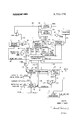
- justification computer 3 which computes a justification solution for output lines
- printer control 4 printer control 4
- printer 5 printer 5.
- justification computer 3 generates read commands or signals which are applied along line I01 to record reader 1.
- Codes read by record reader 1 provide signals which are applied along line 160, through OR gate 9, and then along the input data buss made up of lines 167, 168, I69, I02, and 170.
- Justification computer 3 accumulates justification information such as the escapement value of each character and space along with the number of characters and spaces on each line and computes the justification solutions. Further, the justification computer controls the memory address counter within buffer 2 where operations such as determining the addressing and location of each character are accomplished. The memory address counter advances sequentially with each read or write command applied along lines 152 or 153. Signals representing the buffer address are also fed back to justification computer 3 along line 26, and the address of the first data code of each current line is stored.
- printer control 4 Another input to printer control 4 is the escapement value assigned to each space in accordance with the computed justification solution for the output line, and this is applied along line 104.
- the justification computer outputs a carrier return signal which is applied along line 103 causing the carrier of the printer 5 to return to the left margin for the beginning of the next line. At this time there may be data codes in the buffer which were not printed. These will be on the next line.
- the scan latch 16 is set, and an indication thereof to the justification computer is applied along line 106.
- Justification computer 3 thereafter outputs read signals to buffer 2 along line 152 and the data codes following the last character printed appear sequentially on the output data buss made up of lines 162, 155, 158, 156, 157, and 100. In this instance, these codes are not transmitted to printer control 4 to be printed since the condition scan is applied to AND gate 11. is Instead the codes are applied along line 100 to AND gate 8 which, since its other input scan is true, passes them along line 150, through OR gate 9 to the input data buss. As these codes are sequentially applied to the input data buss, the justification computer tabulates the escapement values of the characters and spaces represented by the codes, and the code counter 12 increments once for each code. The justitication computer does not apply write commands to the buffer since the codes are already stored therein.
- EOM decode 7 When the EOM input code previously written into the buffer following the last data code input appears on the output data buss, an indication thereof is provided by EOM decode 7. This signal causes scan latch 16 to reset, terminating the scan operation. At the termination of the scan operation the data codes input, but not printed on the previous line, have been tabulated in the justification computer and counted in the code counter 12 in the same manner as input data codes read by record reader 1. Thereafter the justification computer resumes applying record read signals along line 101 in order to complete the input for the new line.
- the input to code counter 12 applied along line 170 is dependent on the coincidence of a NOT EOM signal and codes applied along line 102 through AND gate 25. Therefore, code counter 12 does not increment on the EOM input code.
- the NOT EOM signal is derived from inverter 30, inverting the EOM signal detected by decode 7.
- buffer 2 is provided with similar well known gating means which prevent the counting of EOM input codes by the memory address counter. The result is that the code for the first character upon the resumption of codes being read by the record reader will be written in the position formerly occupied by the EOM input code. That is, this code is effectively removed from the buffer.
- buffer full latch 14 is set by the output of detector 13 applied along line 171. With buffer full latch 14 set, a signal is output to 1.) the justification computer 3 along line 105, and 2.) the code generator 19 along line 163.
- a signaling code being an end of input memory code (EOM input code) is generated by code generator 19. This is a special code which is applied to AND gate 10. The condition buffer full from buffer full latch 14 and the signal NOT scan satisfy the conditions for gating the EOM input code through AND gate 10, OR gate 9, and along lines 167 and 168 into buffer 2 upon a write pulse applied along line 152. Thus, this code is stored in the buffer after n-l codes have been counted and stored.
- Code generator 19 is shown separately to make the drawing more easily understood. As is obvious however, justification computer 3 will include a code generator (for applying EOM input codes along line 27 to buffer 2) which could be used for generating the same code that is generated by generator 19.
- buffer full latch 14 The output of buffer full latch 14 is applied along line to the justification computer 3, causes the EOM input code to be stored in buffer 2, and causes justification computer 3 to cease outputting record read signals to record reader 1 along line 101.
- justification computer 3 With the buffer now full, containing 01-! data codes plus the EOM input code, in order to provide for the additional codes necessary to justify the line, it is necessary to output some of the data contained in the buffer to make room for more data.
- justification computer 3 first applies signals to the memory address counter within buffer 2 along line 154 to reset it to the address following the last data code printed. Then, justification computer 3 applies read signals to buffer 2 along line 152 causing buffer 2 to output data to the output data buss.
- data codes output to the output data buss, and particularly along lines 162 and 155, are applied to AND gate 11.
- the data codes are applied along line 110 to printer control 4.
- the scan condition from scan latch 16 is not met since a space code has not been applied to AND gate 15.
- the output of printer control 4 is applied along line 159 to printer 5 which is caused to begin a printing operation. As characters corresponding to the codes are printed, more room is made within the buffer.
- space decode 6 Upon the occurrence of a space code on the output data buss, an indication thereof is detected, and an output is generated by space decode 6 which receives an input applied along lines 162, 158 and 157.
- the space printed upon the occurrence of a space code at this time has a predetermined escapement value, or a minimum interword space size is used, and calculations after this space will include the next character.
- the minimum interword space size can be the same minimum interword spacing employed during justification.
- Code counter 12 which had previously counted n-l input codes and which was previously reset along line I66 by a buffer full signal from buffer full latch 14 applied to OR gate 17, will now count up again, incrementing once for each code coincident with a NOT EOM signal at AND gate 25.
- EOM input code which was stored in the buffer after the storage of n-l data codes, is detected and an EOM signal is generated by EOM decode 7, buffer full latch 14 will be reset by a pulse applied along line 164. This is due to the coincidence of the EOM signal and the scan signal applied to AND gate I8 and gated through OR gate 20. Also, the BOM signal will cause scan latch 16 to reset. This results in justification computer 3 signaling record reader I along line 101 for output reading of more data codes.
- justification computer 3 tabulates the sum of escapement values of data codes representing characters and spaces printed during the time there is a buffer full signal. This occurs in order that these values may be considered when calculating the justification solution for the remainder of the line.
- the justification computer 3 When sufficient codes have been stored in the buffer 2, without exceeding the capacity thereof, for computing a justification solution, the justification computer 3 will compute a solution based on the number of spaces remaining in the buffer 2 and the number of escapement units to the last character to be printed, and will effect a solution for the remainder of the line.
- AND gates 8, 10, ll, 25, and OR gates 9 and 20 are symbolic of a plurality of similar gates while the inverter 30 is symbolic of a single gate. Additionally, data lines 100, 102, 110, 150, 27, etc., are symbolic of a plurality of signal lines.
Landscapes
- Record Information Processing For Printing (AREA)
- Data Exchanges In Wide-Area Networks (AREA)
- Financial Or Insurance-Related Operations Such As Payment And Settlement (AREA)
Applications Claiming Priority (1)
| Application Number | Priority Date | Filing Date | Title |
|---|---|---|---|
| US10172170A | 1970-12-28 | 1970-12-28 |
Publications (1)
| Publication Number | Publication Date |
|---|---|
| US3760376A true US3760376A (en) | 1973-09-18 |
Family
ID=22286059
Family Applications (1)
| Application Number | Title | Priority Date | Filing Date |
|---|---|---|---|
| US00101721A Expired - Lifetime US3760376A (en) | 1970-12-28 | 1970-12-28 | System for controlling output lines with limited storage capacity |
Country Status (10)
| Country | Link |
|---|---|
| US (1) | US3760376A (enExample) |
| JP (1) | JPS5123414B1 (enExample) |
| CA (1) | CA936622A (enExample) |
| CH (1) | CH533013A (enExample) |
| DE (1) | DE2163196B2 (enExample) |
| ES (1) | ES398104A1 (enExample) |
| FR (1) | FR2120712A5 (enExample) |
| GB (1) | GB1360074A (enExample) |
| IT (1) | IT943919B (enExample) |
| NL (1) | NL7117432A (enExample) |
Cited By (14)
| Publication number | Priority date | Publication date | Assignee | Title |
|---|---|---|---|---|
| US3895704A (en) * | 1972-05-18 | 1975-07-22 | Little Inc A | Word processor with right-hand margin control |
| US3924722A (en) * | 1973-02-27 | 1975-12-09 | Cpt Corp | Typewriter with electronic keyboard |
| US3999164A (en) * | 1974-05-13 | 1976-12-21 | Casio Computer Co., Ltd. | Printing device |
| US3999168A (en) * | 1974-11-11 | 1976-12-21 | International Business Machines Corporation | Intermixed pitches in a buffered printer |
| US4000486A (en) * | 1973-10-23 | 1976-12-28 | International Business Machines Corporation | Full page, raster scan, proportional space character generator |
| US4005390A (en) * | 1974-11-11 | 1977-01-25 | International Business Machines Corporation | Merger and multiple translate tables in a buffered printer |
| US4007442A (en) * | 1974-11-11 | 1977-02-08 | International Business Machines Corporation | Intermixed line heights and blank line formation in a buffered printer |
| US4031519A (en) * | 1974-11-11 | 1977-06-21 | Ibm Corporation | Printer |
| US4138719A (en) * | 1974-11-11 | 1979-02-06 | Xerox Corporation | Automatic writing systems and methods of word processing therefor |
| US4198681A (en) * | 1977-01-25 | 1980-04-15 | International Business Machines Corporation | Segmented storage logging and controlling for partial entity selection and condensing |
| US4435762A (en) | 1981-03-06 | 1984-03-06 | International Business Machines Corporation | Buffered peripheral subsystems |
| US4689764A (en) * | 1981-10-26 | 1987-08-25 | International Business Machines Corporation | Method and apparatus for formatting a line of text containing a complex character prior to text justification |
| US4904099A (en) * | 1977-01-14 | 1990-02-27 | Shintaro Abe | Electronic typewriter |
| US5220623A (en) * | 1983-11-02 | 1993-06-15 | Canon Kabushiki Kaisha | Image processing apparatus which can shift reproduction position of image areas, character train, etc. |
Families Citing this family (2)
| Publication number | Priority date | Publication date | Assignee | Title |
|---|---|---|---|---|
| US3998311A (en) * | 1975-01-17 | 1976-12-21 | International Business Machines Corporation | Indicating entry into a variable width right margin zone |
| DE2751326C3 (de) * | 1977-11-17 | 1985-05-09 | Dr.-Ing. Rudolf Hell Gmbh, 2300 Kiel | Verfahren zum Aufzeichnen von Schrift- oder Bildinformationen |
Citations (5)
| Publication number | Priority date | Publication date | Assignee | Title |
|---|---|---|---|---|
| US2848049A (en) * | 1956-09-04 | 1958-08-19 | Mergenthaler Linotype Gmbh | Justification information computer and tape perforator for photocomposing machines |
| US3293613A (en) * | 1963-04-05 | 1966-12-20 | Potter Instrument Co Inc | Information recording system |
| US3299408A (en) * | 1963-08-27 | 1967-01-17 | Wang Laboratories | Data translation system |
| US3307154A (en) * | 1962-10-11 | 1967-02-28 | Compugraphic Corp | Data processing apparatus for line justification in type composing machines |
| US3439341A (en) * | 1965-08-09 | 1969-04-15 | Lockheed Aircraft Corp | Hyphenation machine |
-
1970
- 1970-12-28 US US00101721A patent/US3760376A/en not_active Expired - Lifetime
-
1971
- 1971-11-02 JP JP46086811A patent/JPS5123414B1/ja active Pending
- 1971-11-16 FR FR7141959A patent/FR2120712A5/fr not_active Expired
- 1971-11-29 GB GB5528471A patent/GB1360074A/en not_active Expired
- 1971-12-13 CH CH1814271A patent/CH533013A/de not_active IP Right Cessation
- 1971-12-14 CA CA130052A patent/CA936622A/en not_active Expired
- 1971-12-14 IT IT32345/71A patent/IT943919B/it active
- 1971-12-18 ES ES398104A patent/ES398104A1/es not_active Expired
- 1971-12-20 DE DE2163196A patent/DE2163196B2/de not_active Ceased
- 1971-12-20 NL NL7117432A patent/NL7117432A/xx unknown
Patent Citations (5)
| Publication number | Priority date | Publication date | Assignee | Title |
|---|---|---|---|---|
| US2848049A (en) * | 1956-09-04 | 1958-08-19 | Mergenthaler Linotype Gmbh | Justification information computer and tape perforator for photocomposing machines |
| US3307154A (en) * | 1962-10-11 | 1967-02-28 | Compugraphic Corp | Data processing apparatus for line justification in type composing machines |
| US3293613A (en) * | 1963-04-05 | 1966-12-20 | Potter Instrument Co Inc | Information recording system |
| US3299408A (en) * | 1963-08-27 | 1967-01-17 | Wang Laboratories | Data translation system |
| US3439341A (en) * | 1965-08-09 | 1969-04-15 | Lockheed Aircraft Corp | Hyphenation machine |
Non-Patent Citations (1)
| Title |
|---|
| I.B.M. Technical Disclosure Bulletin, Vol. 4, No. 12, May 1962, pages 67 70, Composing Machine by Lincoln et al. * |
Cited By (14)
| Publication number | Priority date | Publication date | Assignee | Title |
|---|---|---|---|---|
| US3895704A (en) * | 1972-05-18 | 1975-07-22 | Little Inc A | Word processor with right-hand margin control |
| US3924722A (en) * | 1973-02-27 | 1975-12-09 | Cpt Corp | Typewriter with electronic keyboard |
| US4000486A (en) * | 1973-10-23 | 1976-12-28 | International Business Machines Corporation | Full page, raster scan, proportional space character generator |
| US3999164A (en) * | 1974-05-13 | 1976-12-21 | Casio Computer Co., Ltd. | Printing device |
| US4007442A (en) * | 1974-11-11 | 1977-02-08 | International Business Machines Corporation | Intermixed line heights and blank line formation in a buffered printer |
| US4005390A (en) * | 1974-11-11 | 1977-01-25 | International Business Machines Corporation | Merger and multiple translate tables in a buffered printer |
| US3999168A (en) * | 1974-11-11 | 1976-12-21 | International Business Machines Corporation | Intermixed pitches in a buffered printer |
| US4031519A (en) * | 1974-11-11 | 1977-06-21 | Ibm Corporation | Printer |
| US4138719A (en) * | 1974-11-11 | 1979-02-06 | Xerox Corporation | Automatic writing systems and methods of word processing therefor |
| US4904099A (en) * | 1977-01-14 | 1990-02-27 | Shintaro Abe | Electronic typewriter |
| US4198681A (en) * | 1977-01-25 | 1980-04-15 | International Business Machines Corporation | Segmented storage logging and controlling for partial entity selection and condensing |
| US4435762A (en) | 1981-03-06 | 1984-03-06 | International Business Machines Corporation | Buffered peripheral subsystems |
| US4689764A (en) * | 1981-10-26 | 1987-08-25 | International Business Machines Corporation | Method and apparatus for formatting a line of text containing a complex character prior to text justification |
| US5220623A (en) * | 1983-11-02 | 1993-06-15 | Canon Kabushiki Kaisha | Image processing apparatus which can shift reproduction position of image areas, character train, etc. |
Also Published As
| Publication number | Publication date |
|---|---|
| DE2163196A1 (de) | 1972-07-06 |
| ES398104A1 (es) | 1974-07-01 |
| IT943919B (it) | 1973-04-10 |
| DE2163196B2 (de) | 1973-09-27 |
| GB1360074A (en) | 1974-07-17 |
| CA936622A (en) | 1973-11-06 |
| CH533013A (de) | 1973-01-31 |
| FR2120712A5 (enExample) | 1972-08-18 |
| NL7117432A (enExample) | 1972-06-30 |
| JPS5123414B1 (enExample) | 1976-07-16 |
Similar Documents
| Publication | Publication Date | Title |
|---|---|---|
| US3760376A (en) | System for controlling output lines with limited storage capacity | |
| US3248705A (en) | Automatic editor | |
| US4092729A (en) | Apparatus for automatically forming hyphenated words | |
| US3815104A (en) | Information processing system | |
| US3968868A (en) | Format control system for positioning final copy printed text | |
| US3999164A (en) | Printing device | |
| GB1296174A (enExample) | ||
| JPS4812650B1 (enExample) | ||
| US5033879A (en) | Electronic typewriter | |
| US3289176A (en) | Data processing apparatus | |
| US4207011A (en) | Line spacing and column format control system | |
| GB1275001A (en) | Programmable electronic calculator | |
| US3885663A (en) | Control device for tabulation printing | |
| US3868645A (en) | Apparatus for automatically finding microdocuments on a film | |
| US3753239A (en) | Data flow in a machine log system | |
| CA1107865A (en) | Tabulation control system | |
| US3827357A (en) | On-the-fly printer with shortened print cycle | |
| US3998311A (en) | Indicating entry into a variable width right margin zone | |
| US3685019A (en) | Editing apparatus | |
| US3483527A (en) | Efficient justification quality control | |
| US3524528A (en) | Printer paper feed control system | |
| US3755784A (en) | System for revision line retrieval | |
| US3573735A (en) | Production of justified coded tape for page printing | |
| US3744033A (en) | Text formatting for display | |
| GB2247763A (en) | Word processor having a word frequency count unit |