US3754425A - Rolling mills - Google Patents
Rolling mills Download PDFInfo
- Publication number
- US3754425A US3754425A US00162499A US16249971A US3754425A US 3754425 A US3754425 A US 3754425A US 00162499 A US00162499 A US 00162499A US 16249971 A US16249971 A US 16249971A US 3754425 A US3754425 A US 3754425A
- Authority
- US
- United States
- Prior art keywords
- pass
- sizing
- passes
- rollers
- last
- Prior art date
- Legal status (The legal status is an assumption and is not a legal conclusion. Google has not performed a legal analysis and makes no representation as to the accuracy of the status listed.)
- Expired - Lifetime
Links
- 238000005096 rolling process Methods 0.000 title claims abstract description 22
- 238000004513 sizing Methods 0.000 claims abstract description 64
- 230000009467 reduction Effects 0.000 claims abstract description 10
- 239000002184 metal Substances 0.000 claims description 4
- 239000000463 material Substances 0.000 description 18
- 230000007246 mechanism Effects 0.000 description 2
- 229910000831 Steel Inorganic materials 0.000 description 1
- 238000006073 displacement reaction Methods 0.000 description 1
- 239000010959 steel Substances 0.000 description 1
Images
Classifications
-
- B—PERFORMING OPERATIONS; TRANSPORTING
- B21—MECHANICAL METAL-WORKING WITHOUT ESSENTIALLY REMOVING MATERIAL; PUNCHING METAL
- B21B—ROLLING OF METAL
- B21B1/00—Metal-rolling methods or mills for making semi-finished products of solid or profiled cross-section; Sequence of operations in milling trains; Layout of rolling-mill plant, e.g. grouping of stands; Succession of passes or of sectional pass alternations
- B21B1/16—Metal-rolling methods or mills for making semi-finished products of solid or profiled cross-section; Sequence of operations in milling trains; Layout of rolling-mill plant, e.g. grouping of stands; Succession of passes or of sectional pass alternations for rolling wire rods, bars, merchant bars, rounds wire or material of like small cross-section
- B21B1/18—Metal-rolling methods or mills for making semi-finished products of solid or profiled cross-section; Sequence of operations in milling trains; Layout of rolling-mill plant, e.g. grouping of stands; Succession of passes or of sectional pass alternations for rolling wire rods, bars, merchant bars, rounds wire or material of like small cross-section in a continuous process
Definitions
- ABSTRACT A rolling mill is provided having a roll line made up of a plurality of successive three roll stands, each defining a pass, which line includes at least two sizing passes disposed beyond a row of flat passes, the rolls of each sizing pass having sizing grooves shaped so that the reduction in cross section of the work in the pass defined by the sizing grooves is at an analytical minimum when the work is in a non twisted state between passes.
- This invention relates to rolling mills and particularly to sizing passes for small-section rolling mills, such as wire rolling mills, having three-roller passes of which at least two sizing passes are provided beyond a row of flat passes.
- a plurality of round passes for sizing directly follow a row of flat passes, all the passes in the row being alternately angularly offset relatively to one another by half the pitch angle between the roller axes.
- the round passes are open towards the roller gap, the size of the opening becoming smaller towards the last pass.
- the workmaterial emerges from the last flat pass in the form of a hexagon whose cross section has three short sides and three long sides in an alternating order. The three long sides of the hexagonal cross section are produced by the working surfaces of the rollers of the last flat pass, while the three short sides are formed by slight underfilling of the pass in the region of the gaps.
- a feature of this invention is to design the calibrating passes such that stable, twist-free guidance of the workmaterial is ensured.
- the pass grooves in the sizing passes are so designed that the reductions in cross section achieved in the said passes are an analytical minimum when the work-material is in the nonturned state.
- the cross section of the work-material is always placed in the following pass in the position in which it receives the minimum reduction in cross section, i.e. it progresses through the passes without twisting.
- the rollers forming the sizing passes have conic profiles which are disposed symmetrically of the bottom of the pass groove and which, alternating from pass to pass, have in the bottom of each pass groove a radius of curvature which is alternately greater and less than the distance between the centre of the pass and the bottom of the pass groove.
- rollers can be readily provided with conic profiles by means of tools which may be manufactured by appropriate grinding of round steel.
- the rollers of the last but one sizing pass or, if four or five sizing passes are provided, the last but three of the sizing passes, may have an arcuate profile whose radius of curvature is greater than the distance between the centre of the pass and the bottom of the pass grooves.
- the arcuate profile has the advantage that it is the simplest of all conic profiles to produce.
- the uneven numbered sizing passes i.e., the last sizing pass and, if provided, the second from last and the fourth from last sizing passes, have to be formed by rollers whose profiles have a curvature composed of different radii of curvature, for example an elliptical curvature, the radius of curvature located in the bottom of the pass groove being the small circle. If an even number of sizing passes is provided, the first sizing pass following the row of flat passes may be disposed without angular displacement relative to the last pass in the row of flat passes.
- the last flat pass maybe provided with a comparatively slight reduction such that, in the hexagonal cross section resulting in the said flat pass, the three sides of the hexagon abutting against the rollers are the shorter.
- rollers of the last sizing pass may have an arcuate profile whose radius of curvature must, of course, be smaller than the distance between the centre of the pass and the bottoms of the pass grooves.
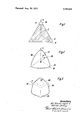
- FIG. 1 diagrammatically illustrates the last pass in a row of flat passes in a rolling mill in accordance with the invention
- FIG. 2 diagrammatically illustrates the first of two sizing passes in the rolling mill
- FIG. 3 diagrammatically illustrates the second or last sizing pass.
- successive passes in a rolling mill are defined by three-roller stands arranged in a line with the passes, are alternately angularly offset relatively to one another by half a pitch angle, i.e., half the angle between the roller axes.
- Two sizing passes are provided beyond a row of flat passes.
- the rollers are disc-like and in each stand, the three rollers are arranged with their axes at v to one another.
- the last pass 10 of the rowof flat passes is formed by three disc-like rollers 4, 6 and 8, whose perpheries only are shown and the strand or work-material leaves the last pass 10 with a hexagonal cross section which has three equal short sides and three equal long sides in alternating order.
- the long sides of the hexagonal cross section are produced by the rollers 4, 6 and 8 defining the pass, while the short sides are produced by slightly under-filling the pass between the rollers in the region 7 of the gaps 9 formed between adjacent rollers.
- the first sizing pass 12 illustrated in FIG. 2 is arranged immediately behind the last pass 10 and is formed by three rollers 14, 26 and 18 each of which has a pass groove with an arcuate profile.
- the radius 20 of curvature of the roller profile is greater than the distance 22 between the centre 24 of the pass and the bottom 26 of the pass groove.
- the first sizing pass which is the last pass but one, is disposed beyond the row of flat passes such that the long sides of the work-material 2 of hexagonal cross section abut against the arcuate profiles of the rollers 14, 16 and 18 while the short sides of the hexagon run into the pass 12 in the region of the gaps 9 located between adjacent rollers.
- the first sizing pass 12 is not angularly offset relative to the last pass in the row of flat passes.
- the cross section of the work-material running through the sizing pass 12 is subjected to the minimum of deformation so long as it runs through the pass 12 in a non-twisted state.
- the second or last sizing pass 34 formed by the rollers 28, 30 and 32 is angularly offset relative to the preceding sizing pass 12 by half a pitch angle, i.e., by 60 the pitch angle being the angle between the normals to the roller axes.
- the profiles of the pass grooves of the rollers 28, 30 and 32 forming this pass have an elliptical curvature which is symmetrical about the bottom of the pass groove.
- the shape of the ellipse is such that the radius 36 of the small circle at the bottom of the pass groove is less than the distance between the centre of the pass and the bottom of the pass groove, the radius of curvature of the bottom of the pass groove corresponding to the small circle radius 36 of the ellipse.
- the first sizing pass is angularly offset by half a pitch angle relative to the last pass in the row of flat passes, which might be more advantageous with respect to the arrangement of the drive mechanisms for the rollers and the direction of rotation, and, like the last sizing pass 34 illustrated in the drawings, has elliptical profiles in which the small circle of the ellipse is located in the bottom of the pass groove.
- the configuration and arrangement of the following sizing passes may be the same as in the case of the passes 12 and 34 of the previously described embodiment.
- two sizing passes are provided as in the case of the grooving illustrated in the drawings.
- two sizing passes are provided as in the case of the grooving illustrated in the drawings.
- the first sizing pass which has the same configuration as the pass 12 illustrated in FIG. 2, has to be angularly offset by half a pitch angle relative to the last pass in the row of flat passes.
- the last pass in the. row of flat passes has to be designed such that only a slight reduction in the cross section of the work-material is effected in this pass.
- the three sides of the hexagonal cross section of the work-material abutting against the rollers thus remain shorter than the three sides of the hexagon facing the gaps between the rollers.
- the reduction in the cross section is again a minimum in the first and second sizing passes when the work-material is not turned or twisted.
- a rolling mill comprising a roll line having a plurality of successive three-roll stands each defining a pass line including a last flat pass intermediate the ends of the pass line having rolls with means to roll metal stock into a generally equilateral triangle having equally truncated apices at all angles, at least two sizing passes disposed after said last flat pass, the rolls of a first sizing pass having arcuate sizing grooves so shaped that the radius of curvature at the bottom of the groove is greater than the distance between the axis of the pass and the bottom of the groove and the rolls of a second sizing pass having arcuate sizing grooves shaped so that the curvature of the grooves is elliptical with the radius of curvature at the bottom of the groove being a smaller circle and being less than the distance between the axis of the pass and the bottom of the arcuate groove, said rollers of said first and second sizing passes being offset relative to one another by half a pitch angle.
Landscapes
- Engineering & Computer Science (AREA)
- Mechanical Engineering (AREA)
- Metal Rolling (AREA)
- Reduction Rolling/Reduction Stand/Operation Of Reduction Machine (AREA)
Abstract
A rolling mill is provided having a roll line made up of a plurality of successive three roll stands, each defining a pass, which line includes at least two sizing passes disposed beyond a row of flat passes, the rolls of each sizing pass having sizing grooves shaped so that the reduction in cross section of the work in the pass defined by the sizing grooves is at an analytical minimum when the work is in a non twisted state between passes.
Description
United States Patent [1 1 Bindernagel et a1.
ROLLING MILLS Inventors: A11 Bindernagel,
Dusselfdorf-Oberkassel; Werner Demny, Dusseldorf, both of Germany Friedrick Rocks, Dusseldorf, Germany Filed: July 14, 1971 Appl. No.: 162,499
Assignee:
Foreign Application Priority m July 7, 1970 Germany P 20 35 482.9
US. Cl. 72/234, 72/224 Int. Cl B2lb 13/08, B21b 13/10 Field of Search 72/234, 235, 224
References Cited UNITED STATES PATENTS 2/1971 Cofer..; 164/76X Aug. 28, 1973 3,380,278 4/1968 Dilling 72/224 3,243,983 4/1966 Norlindh et a1 72/235 3,618,354 11/1971 Bindemagel et a1... 72/224 3,643,488 2/1972 Bretschneider 72/191 Primary Examiner-Milton S. Mehr Attorney-Eugene F. Buell et a1.
[57] ABSTRACT A rolling mill is provided having a roll line made up of a plurality of successive three roll stands, each defining a pass, which line includes at least two sizing passes disposed beyond a row of flat passes, the rolls of each sizing pass having sizing grooves shaped so that the reduction in cross section of the work in the pass defined by the sizing grooves is at an analytical minimum when the work is in a non twisted state between passes.
4 Claims, 3 Drawing Figures Patented Aug. 28, 1973 3,754,425
lnvenlars. 422'22' axmgyez ,2
ROLLING MILLS This invention relates to rolling mills and particularly to sizing passes for small-section rolling mills, such as wire rolling mills, having three-roller passes of which at least two sizing passes are provided beyond a row of flat passes.
In previously proposed rolling mills of this kind, a plurality of round passes for sizing directly follow a row of flat passes, all the passes in the row being alternately angularly offset relatively to one another by half the pitch angle between the roller axes. To enable the work-material to be broadened, the round passes are open towards the roller gap, the size of the opening becoming smaller towards the last pass. The workmaterial emerges from the last flat pass in the form of a hexagon whose cross section has three short sides and three long sides in an alternating order. The three long sides of the hexagonal cross section are produced by the working surfaces of the rollers of the last flat pass, while the three short sides are formed by slight underfilling of the pass in the region of the gaps. When the work-material, provided with this cross section, enters the first sizing pass, there is the risk of the workmaterial twisting between passes such that the short sides of the cross section lie in the pass openings located in the region of the gaps. Similarly, there is the risk of the work-material twisting by half a pitch angle between the individual round passes, so that the portion of the cross section, which has passed through the opening in the preceding round pass, again lies in the angularly offset opening in the next pass. This results in a surface finish marred by ribs which impair further processing. Moreover, twisting of the work-material results in a non-circular finished cross section, and the wear on the rollers is increased by non-uniform progress of the work-material through the passes.
Attempts have been made to prevent twisting of the work-material by means of additional guides, although this measure does not always act in a reliable manner and it is also expensive.
A feature of this invention is to design the calibrating passes such that stable, twist-free guidance of the workmaterial is ensured.
In accordance with the invention, the pass grooves in the sizing passes are so designed that the reductions in cross section achieved in the said passes are an analytical minimum when the work-material is in the nonturned state.
In rolling mills according to. this invention, the cross section of the work-material is always placed in the following pass in the position in which it receives the minimum reduction in cross section, i.e. it progresses through the passes without twisting.
A large number of shapes are possible for the pass grooves in the rolling mill according to the invention. Preferably, the rollers forming the sizing passes have conic profiles which are disposed symmetrically of the bottom of the pass groove and which, alternating from pass to pass, have in the bottom of each pass groove a radius of curvature which is alternately greater and less than the distance between the centre of the pass and the bottom of the pass groove.
The rollers can be readily provided with conic profiles by means of tools which may be manufactured by appropriate grinding of round steel.
Alternatively, the rollers of the last but one sizing pass or, if four or five sizing passes are provided, the last but three of the sizing passes, may have an arcuate profile whose radius of curvature is greater than the distance between the centre of the pass and the bottom of the pass grooves. The arcuate profile has the advantage that it is the simplest of all conic profiles to produce. However, the uneven numbered sizing passes, i.e., the last sizing pass and, if provided, the second from last and the fourth from last sizing passes, have to be formed by rollers whose profiles have a curvature composed of different radii of curvature, for example an elliptical curvature, the radius of curvature located in the bottom of the pass groove being the small circle. If an even number of sizing passes is provided, the first sizing pass following the row of flat passes may be disposed without angular displacement relative to the last pass in the row of flat passes.
However, when there is an even number of sizing passes and the first sizing pass has to be angularly offset relative to the last pass in the row of flat passes because of the arrangement of the roller drives, the last flat pass maybe provided with a comparatively slight reduction such that, in the hexagonal cross section resulting in the said flat pass, the three sides of the hexagon abutting against the rollers are the shorter.
Alternatively, however, the rollers of the last sizing pass may have an arcuate profile whose radius of curvature must, of course, be smaller than the distance between the centre of the pass and the bottoms of the pass grooves.
In the foregoing general description of this invention certain objects, purposes and advantages have been set out. Other objects purposes and advantages will be apparent from a consideration of the following description and the accompanying drawings, in which:
FIG. 1 diagrammatically illustrates the last pass in a row of flat passes in a rolling mill in accordance with the invention,
FIG. 2 diagrammatically illustrates the first of two sizing passes in the rolling mill, and
FIG. 3 diagrammatically illustrates the second or last sizing pass.
In the embodiment illustrated in the drawings, successive passes in a rolling mill, e.g., a rod mill, are defined by three-roller stands arranged in a line with the passes, are alternately angularly offset relatively to one another by half a pitch angle, i.e., half the angle between the roller axes. Two sizing passes are provided beyond a row of flat passes. The hexagonal cross section work-material emerging from the row of flat passes being rolled in the two sizing passes to a substantially round profile. The rollers are disc-like and in each stand, the three rollers are arranged with their axes at v to one another.
The last pass 10 of the rowof flat passes is formed by three disc-like rollers 4, 6 and 8, whose perpheries only are shown and the strand or work-material leaves the last pass 10 with a hexagonal cross section which has three equal short sides and three equal long sides in alternating order. The long sides of the hexagonal cross section are produced by the rollers 4, 6 and 8 defining the pass, while the short sides are produced by slightly under-filling the pass between the rollers in the region 7 of the gaps 9 formed between adjacent rollers.
The first sizing pass 12, illustrated in FIG. 2, is arranged immediately behind the last pass 10 and is formed by three rollers 14, 26 and 18 each of which has a pass groove with an arcuate profile. The radius 20 of curvature of the roller profile is greater than the distance 22 between the centre 24 of the pass and the bottom 26 of the pass groove.
The first sizing pass, which is the last pass but one, is disposed beyond the row of flat passes such that the long sides of the work-material 2 of hexagonal cross section abut against the arcuate profiles of the rollers 14, 16 and 18 while the short sides of the hexagon run into the pass 12 in the region of the gaps 9 located between adjacent rollers. In the illustrated embodiment, the first sizing pass 12 is not angularly offset relative to the last pass in the row of flat passes. The cross section of the work-material running through the sizing pass 12 is subjected to the minimum of deformation so long as it runs through the pass 12 in a non-twisted state.
Referring to FIG. 3, the second or last sizing pass 34 formed by the rollers 28, 30 and 32 is angularly offset relative to the preceding sizing pass 12 by half a pitch angle, i.e., by 60 the pitch angle being the angle between the normals to the roller axes. The profiles of the pass grooves of the rollers 28, 30 and 32 forming this pass have an elliptical curvature which is symmetrical about the bottom of the pass groove. The shape of the ellipse is such that the radius 36 of the small circle at the bottom of the pass groove is less than the distance between the centre of the pass and the bottom of the pass groove, the radius of curvature of the bottom of the pass groove corresponding to the small circle radius 36 of the ellipse.
When the last sizing pass 34 has such a configuration and is in this position, the reduction in the cross section of the work-material is again at a minimum so long as the work-material is in the non-twisted state, whereby the work-material is effectively prevented from twisting even in the last sizing pass.
In another embodiment (not illustrated), three sizing passes are provided. In this case, the first sizing pass is angularly offset by half a pitch angle relative to the last pass in the row of flat passes, which might be more advantageous with respect to the arrangement of the drive mechanisms for the rollers and the direction of rotation, and, like the last sizing pass 34 illustrated in the drawings, has elliptical profiles in which the small circle of the ellipse is located in the bottom of the pass groove. The configuration and arrangement of the following sizing passes may be the same as in the case of the passes 12 and 34 of the previously described embodiment.
In a further embodiment (also not illustrated in the drawings), two sizing passes are provided as in the case of the grooving illustrated in the drawings. However, as
a result of a given drive mechanism for the rollers, the first sizing pass, which has the same configuration as the pass 12 illustrated in FIG. 2, has to be angularly offset by half a pitch angle relative to the last pass in the row of flat passes. In this case, the last pass in the. row of flat passes has to be designed such that only a slight reduction in the cross section of the work-material is effected in this pass. The three sides of the hexagonal cross section of the work-material abutting against the rollers thus remain shorter than the three sides of the hexagon facing the gaps between the rollers. In such a case, the reduction in the cross section is again a minimum in the first and second sizing passes when the work-material is not turned or twisted.
In the foregoing specification certain preferred embodiments and practices of this invention have been set out, however it will be understood that this invention may be otherwise practiced within the scope of the following claims.
What we claim is:
l. A rolling mill comprising a roll line having a plurality of successive three-roll stands each defining a pass line including a last flat pass intermediate the ends of the pass line having rolls with means to roll metal stock into a generally equilateral triangle having equally truncated apices at all angles, at least two sizing passes disposed after said last flat pass, the rolls of a first sizing pass having arcuate sizing grooves so shaped that the radius of curvature at the bottom of the groove is greater than the distance between the axis of the pass and the bottom of the groove and the rolls of a second sizing pass having arcuate sizing grooves shaped so that the curvature of the grooves is elliptical with the radius of curvature at the bottom of the groove being a smaller circle and being less than the distance between the axis of the pass and the bottom of the arcuate groove, said rollers of said first and second sizing passes being offset relative to one another by half a pitch angle.
2. A rolling mill as claimed in claim 1, wherein a plurality of first and second sizing passes are provided.
3. A rolling mill as claimed in claim 2, in which the number of sizing passes is even and in which the rollers of the first sizing pass following the row of flat passes is angularly symmetrical relative to those of the last pass in the row of flat passes.
4. A rolling mill as claimed in claim 2, in which the number of sizing passes is even and all the stands are positioned in the line with; the rollers in adjacent stands angularly offset relative to one another, and in which the last flat pass is dimensioned to effect section transverse a reduction of a metal stock having said truncated apices transverse to said rollers.
l I" I =0 8 UNITED STATES PATENT OFFICE v CERTEFICATE 0F CORRECTION Patent No. 3 754 425 Dated August 28 1973 Inventor(s) Ali Bindernagel and Werner Demnv rs in the above-identified patent It is certified that error appea by corrected as shown below:
and that said Letters Patent are here line 49 after "with" delete the man 4 Col 4' Clalm "effect" delete semicolon; I lines 51 and 52 after -section transverse-.
Signed and sealed this 18th day of December 1973.
(SEAL) At'test:
RENE D. TEGTMEYER Attesting Officer
Claims (4)
1. A rolling mill comprising a roll line having a plurality of successive three-roll stands each defining a pass line including a last flat pass intermediate the ends of the pass line having rolls with means to roll metal stock into a generally equilateraL triangle having equally truncated apices at all angles, at least two sizing passes disposed after said last flat pass, the rolls of a first sizing pass having arcuate sizing grooves so shaped that the radius of curvature at the bottom of the groove is greater than the distance between the axis of the pass and the bottom of the groove and the rolls of a second sizing pass having arcuate sizing grooves shaped so that the curvature of the grooves is elliptical with the radius of curvature at the bottom of the groove being a smaller circle and being less than the distance between the axis of the pass and the bottom of the arcuate groove, said rollers of said first and second sizing passes being offset relative to one another by half a pitch angle.
2. A rolling mill as claimed in claim 1, wherein a plurality of first and second sizing passes are provided.
3. A rolling mill as claimed in claim 2, in which the number of sizing passes is even and in which the rollers of the first sizing pass following the row of flat passes is angularly symmetrical relative to those of the last pass in the row of flat passes.
4. A rolling mill as claimed in claim 2, in which the number of sizing passes is even and all the stands are positioned in the line with; the rollers in adjacent stands angularly offset relative to one another, and in which the last flat pass is dimensioned to effect section transverse a reduction of a metal stock having said truncated apices transverse to said rollers.
Applications Claiming Priority (1)
| Application Number | Priority Date | Filing Date | Title |
|---|---|---|---|
| DE19702035482 DE2035482C2 (en) | 1968-12-12 | 1970-07-17 | Roll calibration for fine iron, especially for wire rolling mills |
Publications (1)
| Publication Number | Publication Date |
|---|---|
| US3754425A true US3754425A (en) | 1973-08-28 |
Family
ID=5777047
Family Applications (1)
| Application Number | Title | Priority Date | Filing Date |
|---|---|---|---|
| US00162499A Expired - Lifetime US3754425A (en) | 1970-07-17 | 1971-07-14 | Rolling mills |
Country Status (2)
| Country | Link |
|---|---|
| US (1) | US3754425A (en) |
| JP (1) | JPS557321B1 (en) |
Cited By (6)
| Publication number | Priority date | Publication date | Assignee | Title |
|---|---|---|---|---|
| US3952570A (en) * | 1973-07-04 | 1976-04-27 | Firma Friedrich Kocks | Stretch reducing mills |
| FR2312307A1 (en) * | 1975-05-30 | 1976-12-24 | Nippon Steel Corp | PROCESS FOR LAMINING BARS AND RODS WITH A FOUR CYLINDER DEVICE AND APPARATUS FOR ITS IMPLEMENTATION |
| US4099402A (en) * | 1975-06-25 | 1978-07-11 | Mannesmannrohren-Werke, A.G. | Stretch reducing of hollow stock |
| US4838964A (en) * | 1987-03-20 | 1989-06-13 | Xerox Corporation | Process for preparing belts |
| US4959109A (en) * | 1986-03-27 | 1990-09-25 | Xerox Corporation | Apparatus and process for preparing belts |
| US4968369A (en) * | 1988-10-03 | 1990-11-06 | Xerox Corporation | Belt fabrication machine |
Citations (5)
| Publication number | Priority date | Publication date | Assignee | Title |
|---|---|---|---|---|
| US3243983A (en) * | 1962-05-02 | 1966-04-05 | Morgardshammars Mek Verkst Sa | Turnable roll pairs |
| US3380278A (en) * | 1965-10-21 | 1968-04-30 | Titanium Metals Corp | Method and apparatus for drawing solid wire stock |
| US3561105A (en) * | 1967-06-28 | 1971-02-09 | Southwire Co | Method of producing a hot-formed aluminum base product |
| US3618354A (en) * | 1970-05-06 | 1971-11-09 | Kocks Gmbh Friedrich | Methods and apparatus for metal rolling |
| US3643488A (en) * | 1968-12-07 | 1972-02-22 | Siemag Siegener Masch Bau | Rolling mill |
-
1971
- 1971-07-14 US US00162499A patent/US3754425A/en not_active Expired - Lifetime
- 1971-07-16 JP JP5248571A patent/JPS557321B1/ja active Pending
Patent Citations (5)
| Publication number | Priority date | Publication date | Assignee | Title |
|---|---|---|---|---|
| US3243983A (en) * | 1962-05-02 | 1966-04-05 | Morgardshammars Mek Verkst Sa | Turnable roll pairs |
| US3380278A (en) * | 1965-10-21 | 1968-04-30 | Titanium Metals Corp | Method and apparatus for drawing solid wire stock |
| US3561105A (en) * | 1967-06-28 | 1971-02-09 | Southwire Co | Method of producing a hot-formed aluminum base product |
| US3643488A (en) * | 1968-12-07 | 1972-02-22 | Siemag Siegener Masch Bau | Rolling mill |
| US3618354A (en) * | 1970-05-06 | 1971-11-09 | Kocks Gmbh Friedrich | Methods and apparatus for metal rolling |
Cited By (6)
| Publication number | Priority date | Publication date | Assignee | Title |
|---|---|---|---|---|
| US3952570A (en) * | 1973-07-04 | 1976-04-27 | Firma Friedrich Kocks | Stretch reducing mills |
| FR2312307A1 (en) * | 1975-05-30 | 1976-12-24 | Nippon Steel Corp | PROCESS FOR LAMINING BARS AND RODS WITH A FOUR CYLINDER DEVICE AND APPARATUS FOR ITS IMPLEMENTATION |
| US4099402A (en) * | 1975-06-25 | 1978-07-11 | Mannesmannrohren-Werke, A.G. | Stretch reducing of hollow stock |
| US4959109A (en) * | 1986-03-27 | 1990-09-25 | Xerox Corporation | Apparatus and process for preparing belts |
| US4838964A (en) * | 1987-03-20 | 1989-06-13 | Xerox Corporation | Process for preparing belts |
| US4968369A (en) * | 1988-10-03 | 1990-11-06 | Xerox Corporation | Belt fabrication machine |
Also Published As
| Publication number | Publication date |
|---|---|
| JPS557321B1 (en) | 1980-02-25 |
Similar Documents
| Publication | Publication Date | Title |
|---|---|---|
| US3709017A (en) | Method of rolling metal sheet articles between the driven rolls of the roll mill | |
| US3533260A (en) | Rolling of metal billets | |
| US3754425A (en) | Rolling mills | |
| US4191041A (en) | Rolling mills | |
| US5636544A (en) | Cold rolling method for a metal strip and a mill array | |
| AU710014B2 (en) | Method of rolling deformed bar and roll for deformed bar | |
| US3871221A (en) | Continuous strip rolling mill | |
| US3618354A (en) | Methods and apparatus for metal rolling | |
| SU1242267A1 (en) | Method of rolling strips | |
| US4070893A (en) | Finish rolling method for production of round cross-sectional shape materials | |
| SU858955A1 (en) | Continuous rolling mill | |
| RU2764911C1 (en) | Method for rolling railway rails with double slopes of the inner faces of the flanges of the base | |
| DE3924261C2 (en) | Caliber contour of the rolls of a reducing or stretch-reducing mill | |
| US4628718A (en) | Method of rolling to impart triangular section | |
| SU1036408A1 (en) | Blank rolling method | |
| JP3541464B2 (en) | Rolling method for strip steel | |
| JPH0215810A (en) | Roll hole die in roll stand with three or large number of roll | |
| US3533262A (en) | Multiroll tandem mill construction | |
| JPH01210102A (en) | Method for rolling of steel bar stock without holding guide | |
| US6408665B1 (en) | Finish hot rolling method for structural steels | |
| RU2187391C1 (en) | Billet rolling method | |
| SU722617A1 (en) | Round steel rolling method | |
| US3751959A (en) | Forging machine | |
| RU2201817C1 (en) | Installation for multiple-groove rolling of merchant bars | |
| RU2344007C1 (en) | System of roll-passes for rolling sectional rod iron |