US3749048A - Signal divider for speed control of direct reversing gas turbine - Google Patents
Signal divider for speed control of direct reversing gas turbine Download PDFInfo
- Publication number
- US3749048A US3749048A US00231181A US3749048DA US3749048A US 3749048 A US3749048 A US 3749048A US 00231181 A US00231181 A US 00231181A US 3749048D A US3749048D A US 3749048DA US 3749048 A US3749048 A US 3749048A
- Authority
- US
- United States
- Prior art keywords
- signal
- nozzle
- gas turbine
- control
- command signal
- Prior art date
- Legal status (The legal status is an assumption and is not a legal conclusion. Google has not performed a legal analysis and makes no representation as to the accuracy of the status listed.)
- Expired - Lifetime
Links
- 230000002441 reversible effect Effects 0.000 claims description 27
- 239000000446 fuel Substances 0.000 claims description 23
- 230000004044 response Effects 0.000 claims description 6
- 239000012530 fluid Substances 0.000 abstract description 8
- 238000002485 combustion reaction Methods 0.000 description 4
- 230000008901 benefit Effects 0.000 description 2
- 238000012888 cubic function Methods 0.000 description 2
- 230000000694 effects Effects 0.000 description 2
- 230000004048 modification Effects 0.000 description 2
- 238000012986 modification Methods 0.000 description 2
- 230000001133 acceleration Effects 0.000 description 1
- 230000008859 change Effects 0.000 description 1
- 238000010276 construction Methods 0.000 description 1
- 238000000034 method Methods 0.000 description 1
- 238000005192 partition Methods 0.000 description 1
Images
Classifications
-
- B—PERFORMING OPERATIONS; TRANSPORTING
- B63—SHIPS OR OTHER WATERBORNE VESSELS; RELATED EQUIPMENT
- B63H—MARINE PROPULSION OR STEERING
- B63H21/00—Use of propulsion power plant or units on vessels
- B63H21/22—Use of propulsion power plant or units on vessels the propulsion power units being controlled from exterior of engine room, e.g. from navigation bridge; Arrangements of order telegraphs
-
- F—MECHANICAL ENGINEERING; LIGHTING; HEATING; WEAPONS; BLASTING
- F01—MACHINES OR ENGINES IN GENERAL; ENGINE PLANTS IN GENERAL; STEAM ENGINES
- F01D—NON-POSITIVE DISPLACEMENT MACHINES OR ENGINES, e.g. STEAM TURBINES
- F01D1/00—Non-positive-displacement machines or engines, e.g. steam turbines
- F01D1/30—Non-positive-displacement machines or engines, e.g. steam turbines characterised by having a single rotor operable in either direction of rotation, e.g. by reversing of blades
-
- F—MECHANICAL ENGINEERING; LIGHTING; HEATING; WEAPONS; BLASTING
- F01—MACHINES OR ENGINES IN GENERAL; ENGINE PLANTS IN GENERAL; STEAM ENGINES
- F01D—NON-POSITIVE DISPLACEMENT MACHINES OR ENGINES, e.g. STEAM TURBINES
- F01D15/00—Adaptations of machines or engines for special use; Combinations of engines with devices driven thereby
- F01D15/02—Adaptations for driving vehicles, e.g. locomotives
- F01D15/04—Adaptations for driving vehicles, e.g. locomotives the vehicles being waterborne vessels
-
- F—MECHANICAL ENGINEERING; LIGHTING; HEATING; WEAPONS; BLASTING
- F02—COMBUSTION ENGINES; HOT-GAS OR COMBUSTION-PRODUCT ENGINE PLANTS
- F02C—GAS-TURBINE PLANTS; AIR INTAKES FOR JET-PROPULSION PLANTS; CONTROLLING FUEL SUPPLY IN AIR-BREATHING JET-PROPULSION PLANTS
- F02C9/00—Controlling gas-turbine plants; Controlling fuel supply in air- breathing jet-propulsion plants
- F02C9/16—Control of working fluid flow
- F02C9/20—Control of working fluid flow by throttling; by adjusting vanes
- F02C9/22—Control of working fluid flow by throttling; by adjusting vanes by adjusting turbine vanes
Definitions
- ABSTRACT A speed control for a direct reversing gas turbine of the type adapted to separately control the flow of motive fluid through two sets of individually adjustable nozzles into forward and reversing blades on the load turbine.
- a nozzle control derives a command signal for total nozzle flow area from various operating conditions of the gas turbine.
- the command signal is split into ahead and astern nozzle command signals in a ratio which is determined by comparing propulsion lever position and propeller speed.
- the system maintains the desired total nozzle opening from the nozzle control, as well as the desired ratio between ahead and astem nozzle opening.
- the invention relates generally to a speed control for a direct reversing gas turbine, and more particularly to a control for a marine propulsion turbine driving a fixed pitch propeller which is adapted to reverse the direction of the propeller under speed control by means of separately adjustable nozzle blades.
- Control systems for marine gas turbines are known, wherein reversing is accomplished through a reversible pitch propeller and means for adjusting the propeller pitch are incorporated into the control system.
- An example is found in U.S. Pat. No. 3,639,076 issued Feb. 1, I972 toW. l. Rowen and U.S. Pat. No. 2,912,824 issued Nov. 17, 1959 to F. H. Van Nest et al., both of these patents being assigned to the present assignee.
- U.S. Pat. No. 3,638,422 issued Feb. 1, I972 to A. Loft, et al., shows a two-shaft gas turbine control system for setting the total flow through the adjustable nozzle in accordance with a number of operating conditions such as compressor speed and exhaust temperature, so as to satisfy other requirements on the gas turbine, such as a temperature limitation. It would be desirable to continue. to obtain the benefits of the system which enables variations in total gas flow through a nozzle control while at the same time permitting a reversing gas turbine speed control.
- one object of the present invention is to provide an improved control system for a direct reversing gas turbine which splits a command signal for total motive fluid flow into forward and reverse nozzle command signals.
- Another object of the invention is to provide a reversing turbine control system which sets the ratio between ahead and astern nozzle command signals so as to control speed in accordance with a speed setting despite other requirements for flow of total motive fluid through the turbine.
- the invention comprises a control system which accepts a first command signal for total nozzle flow area from a separate nozzle control system and a second signal representing the integrated error between a desired propeller speed represented by propulsion lever setting and actual propeller speed.
- the total nozzle command signal is applied to a forward nozzle controller.
- a fraction of the total nozzle command signal is obtained, as determined by the second speed error signal, and applied with subtractive effect to the ahead nozzle controller.
- the fractional signal is also applied'at the same time to a"reverse nozzle controller.
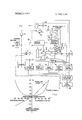
- FIG. I is a simplified schematic view of a marine direct reversing gas turbine with its control system
- FIG. 2 is a graph of propulsion lever characteristics for the direct reversing turbine driving a ship with fixed pitch propeller.
- a gas turbine shown generally as I, has a compressor 2, combustion chambers 3, and a turbine section 4 feeding exhaust gas through exhaust stack 5.
- Turbine section 4 includes two separate shafts, one attached to a turbine wheel 6 which drives compressor 2 and the other attached to a
- the load turbine wheel 7 carries a set of blades especially adapted to accomplish reversal of the load turbine.
- the blades are formed with an outer forward" blade section 13 and an inner reversing blade section 14.
- a circumferential row of outer adjustable nozzle blades 15 control flow of fluid through the forward blade sections 13, while an inner circumferential row of adjustable blades 16 control the flow of reversing motive fluid through the reversing blades 14.
- the arrangement shown is schematic only, but a suitable construction is shown in the aforementioned US. Pat. No. 3,286,982.
- Stationary nozzle blades 17 and turbine blades 18 for the compressor turbine may be conventional.
- the total energy delivered to both of the turbine wheels 6, 7 is determined by controlling the flow of fuel to the combustion chambers 3. This is carried out by means of a fuel control system shown generally at 19. The total energy released in the combustion chambers is divided between the two turbine shafts as determined by the nozzle control shown generally at 20.
- the fuel control 19 and the nozzle control 20 are indicated in very simple schematic form, since other types of fuel and nozzle controls than the ones shown would be suitable for carrying out the present invention. However for purposes of illustration, a typical example of these controls 19, 20, which may be found by reference to the aforementioned US. Pat. Nos. 3,638,422 and 3,639,076, is described briefly below.
- An average exhaust temperature is obtained by device 21 and furnished to a temperature control unit 22 in the fuel control and also to the nozzle control 20.
- a speed and load control 23 and an acceleration control 24 receive load turbine speed signals from sensor 12.
- a start-up control unit 25 develops a schedule of fuel flows for starting the turbine.
- a power governor unit 26 develops a fuel flow signal in accordance with a desired power output. All of the fuel flow signals from units 22-26 are supplied to a low value selecting device 27 which picks the lowest rate of fuel flow and, through a fuel control unit servo 28, sets the stroke of the variable delivery pump 10.
- the selection of the reference signal to the power governor unit 26 is determined by the position of a remote manual control lever 29 which is applied to a electronic cubic function generator 30, which is designed to provide a linear relationship between hand lever position and actual ship's speed.
- the actual fuel flow rate is determined in power governor 26 by a multiplying device which utilizes a signal from the shaft speed sensor 11 and the selected fuel flow signal coming from low value selector 27.
- the nozzle control 20 receives other signals representing operating conditions of the gas turbine such as compressor discharge pressure from a transducer 31 and a compressor shaft speed signal from sensor 11.
- the total nozzle command signal is used to hold the compressor speed constant.
- the actual compressor speed (sensor 11) is compared to a set point which is altered as necessary by variations in other operating conditions such as exhaust temperature and compressor discharge pressure.
- a signal divider for speed control of the reversing gas turbine is indicated generally within box 50.
- a first signal from the nozzle control 20 is applied to a multiplier 32.
- a second signal is applied to multiplier 32 from an integrating amplifier 33 having a diode 34 connected to prevent the output signal from becoming negative.
- a second diode 35 is connected to the tap of an adjustable potentiometer 36 which, in turn, is connected between a negative potential source and the output of amplifier 33.
- the position of the propulsion lever 29 is converted by a high gain device 37 to a signal proportional to position of the lever.
- An input signal of either polarity from device 37 is then applied to amplifier 33.
- a second input to amplifier 33 of opposite polarity and indieative of actual speed of the propeller shaft is obtained from speed sensor 12.
- the first and second signal applied to multiplier 32 are multiplied by one another in such a way that the signal obtained from multiplier 32 is a fractional part of the first signal applied thereto.
- the fraction is between the values of 0 and 1 in proportion to the magnitude of the second signal applied thereto.
- Such multipliers are commercially available, a suitable device being a quarter-squared multiplier, available from the General Electric Company as Directo-Matic II, part
- the output from multiplier 32 is applied to a first summing amplifier 38 which provides a reverse" nozzle command signal, and to a second summing amplifier 37 which when subtracted from a first command signal from the nozzle control, 20 representing desired total area, provides a forward" nozzle command signal.
- the forward nozzle command signal is applied to a positioning servomechanism 40 which adjusts the position of the forward adjustable nozzle blades 15.
- a feedback signal representing the forward nozzle blade positions is supplied back to the input of amplifier 37 through line 41.
- the reverse nozzle command signal from amplifier 38 is supplied to a positioning servo-mechanism 42 which sets the openings of the reverse nozzle blades 16 and their actual position is fed back to the input of amplifier 38 via a line 43.
- FIG. 2 is a graph showing the variations in the power command signal going to the power governor 26 for a given position of the propulsion lever 29, the curved characteristic being obtained from the cubic function generator 30.
- the graph also shows the propeller speed which would result under ideal conditions if the power delivered to the propeller is in accordance with the power command signal.
- the present invention providing for a division of the motive fluid between forward and reversing blade sections takes place in a range of propulsion hand lever positions on the order of 40 percent of the full ahead or astem lever range. In this range, the invention provides for a substantially linear variation of propeller speed with respect to propulsion lever position, while the lever simultaneously sets the total gas turbine available power through a fuel flow command signal.
- the nozzle control provides a total nozzle command signal which sets the combined effective flow area through the separate forward and reversing nozzle blades l5, 16. This total flow is largely determined by the speed of the compressor and has a marked effect on the turbine exhaust temperature.
- the nozzle control exemplified here happens to function so as to hold the compressor speed at a set point which is determined jointly by the exhaust temperature and the compressor discharge pressure.
- any type of nozzle control which gives a command signal for total nozzle flow is suitable for this invention. Accordingly, the total nozzle command signal from nozzle control 20 will vary in accordance with operating conditions of the gas turbine.
- the fraction of the total nozzle command signal which is used to split the flow between forward and reverse blade sections is determined by deviations between desired speed, as set by the propulsion lever 29, and actual propeller speed, as sensed by speed sensor 12. These equal and opposite signals are applied to the integrating amplifier 33 and the integrated error signal therefrom is applied to multiplier 32. The output from multiplier 32 is a fraction of the total nozzle command signal. This fractional signal is used as an input to the reverse nozzle amplifier 38 to set the opening of the reverse adjustable nozzle blades 16. The balance of the total nozzle command signal is obtained from the forward nozzle command amplifier 37 and used to set forward adjustable nozzle blades 15. This balance is obtained in amplifier 37 by subtracting the fractional signal from the total signal supplied by nozzle control 20.
- Deviations between desired propeller speed and actual speed continuously adjust the fractional part of the total nozzle command signal which is used to divide the flow between ahead and astem nozzles.
- the speed change response is good, the only significant inertial elements being the load turbine wheel and the propeller shafting.
- the nozzle control 20 is unaware of the propeller speed, except perhaps through variations in exhaust temperature. It functions in its normal way to keep the exhaust temperature under control by generating new total nozzle command signals so as to vary the power supplied to (and therefore the speed of) the compressor.
- a control system comprising:
- a nozzle control providing a first nozzle command signal in'response to selected operating conditions of the gas turbine for dividing available power between the gas turbine shafts and representing a desired total nozzle opening of both forward and reverse nozzle blades
- a plurality of positioning servomechanisms setting the positions of said forward and reversing adjustable nozzle blades in accordance with said forward and reverse command signals respectively.
- a first summing amplifier connected to receive said fractional signal and to supply the reverse nozzle command signal
- a second amplifier connected to receive said first signal and said fractional signal and to supply the difference therebetween as the forward nozzle command signal.
- said means providing said second signal comprises an integrating summing amplifier connected to receive a load shaft speed command signal and an actual load shaft speed signal and to supply the time integral of the difference therebetween as said second signal.
Landscapes
- Engineering & Computer Science (AREA)
- Mechanical Engineering (AREA)
- General Engineering & Computer Science (AREA)
- Chemical & Material Sciences (AREA)
- Combustion & Propulsion (AREA)
- Radar, Positioning & Navigation (AREA)
- Remote Sensing (AREA)
- Ocean & Marine Engineering (AREA)
- Physics & Mathematics (AREA)
- Fluid Mechanics (AREA)
- Control Of Turbines (AREA)
Applications Claiming Priority (1)
| Application Number | Priority Date | Filing Date | Title |
|---|---|---|---|
| US23118172A | 1972-03-02 | 1972-03-02 |
Publications (1)
| Publication Number | Publication Date |
|---|---|
| US3749048A true US3749048A (en) | 1973-07-31 |
Family
ID=22868078
Family Applications (1)
| Application Number | Title | Priority Date | Filing Date |
|---|---|---|---|
| US00231181A Expired - Lifetime US3749048A (en) | 1972-03-02 | 1972-03-02 | Signal divider for speed control of direct reversing gas turbine |
Country Status (4)
| Country | Link |
|---|---|
| US (1) | US3749048A (en。) |
| JP (1) | JPS5531302B2 (en。) |
| DE (1) | DE2258294A1 (en。) |
| GB (1) | GB1355730A (en。) |
Cited By (4)
| Publication number | Priority date | Publication date | Assignee | Title |
|---|---|---|---|---|
| US3880547A (en) * | 1972-03-28 | 1975-04-29 | Mtu Muenchen Gmbh | Retarding means for gas turbine driven vehicles |
| US4378673A (en) * | 1979-06-04 | 1983-04-05 | Nissan Motor Co., Ltd. | Fuel control system for gas turbine engine |
| US6485340B1 (en) | 1998-11-16 | 2002-11-26 | Bombardier Motor Corporation Of America | Electrically controlled shift and throttle system |
| US20160245172A1 (en) * | 2015-02-23 | 2016-08-25 | Mitsubishi Hitachi Power Systems, Ltd. | Two-Shaft Gas Turbine, and Control System and Control Method of the Gas Turbine |
Families Citing this family (2)
| Publication number | Priority date | Publication date | Assignee | Title |
|---|---|---|---|---|
| JPS50157713A (en。) * | 1974-06-13 | 1975-12-19 | ||
| JP2006274805A (ja) * | 2005-03-28 | 2006-10-12 | Mitsui Eng & Shipbuild Co Ltd | 炉頂圧回収タービンの制御システム |
-
1972
- 1972-03-02 US US00231181A patent/US3749048A/en not_active Expired - Lifetime
- 1972-11-14 GB GB5253572A patent/GB1355730A/en not_active Expired
- 1972-11-29 DE DE19722258294 patent/DE2258294A1/de active Pending
- 1972-12-01 JP JP11991872A patent/JPS5531302B2/ja not_active Expired
Cited By (5)
| Publication number | Priority date | Publication date | Assignee | Title |
|---|---|---|---|---|
| US3880547A (en) * | 1972-03-28 | 1975-04-29 | Mtu Muenchen Gmbh | Retarding means for gas turbine driven vehicles |
| US4378673A (en) * | 1979-06-04 | 1983-04-05 | Nissan Motor Co., Ltd. | Fuel control system for gas turbine engine |
| US6485340B1 (en) | 1998-11-16 | 2002-11-26 | Bombardier Motor Corporation Of America | Electrically controlled shift and throttle system |
| US20160245172A1 (en) * | 2015-02-23 | 2016-08-25 | Mitsubishi Hitachi Power Systems, Ltd. | Two-Shaft Gas Turbine, and Control System and Control Method of the Gas Turbine |
| US10323570B2 (en) * | 2015-02-23 | 2019-06-18 | Mitsubishi Hitachi Power Systems, Ltd. | Two-shaft gas turbine, and control system and control method of the gas turbine |
Also Published As
| Publication number | Publication date |
|---|---|
| JPS5531302B2 (en。) | 1980-08-16 |
| GB1355730A (en) | 1974-06-05 |
| DE2258294A1 (de) | 1973-09-06 |
| JPS48100512A (en。) | 1973-12-19 |
Similar Documents
| Publication | Publication Date | Title |
|---|---|---|
| US2306953A (en) | Gas turbine plant for propulsion of water and air craft | |
| US2280835A (en) | Aircraft | |
| US3932058A (en) | Control system for variable pitch fan propulsor | |
| US3639076A (en) | Constant power control system for gas turbine | |
| US3936226A (en) | Control system for variable pitch fan propulsor with reverse pitch | |
| US2219994A (en) | Gas turbine plant and regulating system therefor | |
| EP0034614B1 (en) | Control system for cheng dual-fluid cycle engine system | |
| US5142860A (en) | Constant thrust retention turbine temperature limit system | |
| US4242864A (en) | Integrated control system for a gas turbine engine | |
| US4648797A (en) | Torque control system | |
| US4772180A (en) | Aircraft thrust control | |
| US2857739A (en) | Control system for turbo-jet engine | |
| US4899537A (en) | Steam-injected free-turbine-type gas turbine | |
| US5211007A (en) | Method of pressure-ratio control of gas turbine engine | |
| US2816417A (en) | Control system for dual rotor pump drives | |
| GB2088961A (en) | Fuel control system for a gas turbine engine | |
| US2613500A (en) | Gas turbine power plant having means for joint control of the fuel and the air supply | |
| CA2976982C (en) | Power plant thrust management system for turboprop engines | |
| US4823546A (en) | Steam-injected free-turbine-type gas turbine | |
| US3168810A (en) | Two shaft gas turbine control system | |
| EP3835199B1 (en) | System and method for propeller speed governing | |
| CA1273211A (en) | Aircraft thrust control | |
| US3729928A (en) | Torque control system for a gas turbine | |
| US4206597A (en) | Fan R.P.M. control loop stabilization using high rotor speed | |
| US3749048A (en) | Signal divider for speed control of direct reversing gas turbine |