US3738457A - Friction mechanisms - Google Patents
Friction mechanisms Download PDFInfo
- Publication number
- US3738457A US3738457A US00104987A US3738457DA US3738457A US 3738457 A US3738457 A US 3738457A US 00104987 A US00104987 A US 00104987A US 3738457D A US3738457D A US 3738457DA US 3738457 A US3738457 A US 3738457A
- Authority
- US
- United States
- Prior art keywords
- friction
- outer layers
- elements
- inner layer
- layers
- Prior art date
- Legal status (The legal status is an assumption and is not a legal conclusion. Google has not performed a legal analysis and makes no representation as to the accuracy of the status listed.)
- Expired - Lifetime
Links
- 230000007246 mechanism Effects 0.000 title claims abstract description 22
- 238000010276 construction Methods 0.000 description 21
- 239000000463 material Substances 0.000 description 7
- 210000002105 tongue Anatomy 0.000 description 6
- 229910000831 Steel Inorganic materials 0.000 description 3
- 239000002131 composite material Substances 0.000 description 3
- 238000004519 manufacturing process Methods 0.000 description 3
- 239000010959 steel Substances 0.000 description 3
- 238000010586 diagram Methods 0.000 description 2
- 238000009826 distribution Methods 0.000 description 2
- 238000009987 spinning Methods 0.000 description 2
- ZOXJGFHDIHLPTG-UHFFFAOYSA-N Boron Chemical compound [B] ZOXJGFHDIHLPTG-UHFFFAOYSA-N 0.000 description 1
- 101100180402 Caenorhabditis elegans jun-1 gene Proteins 0.000 description 1
- OKTJSMMVPCPJKN-UHFFFAOYSA-N Carbon Chemical compound [C] OKTJSMMVPCPJKN-UHFFFAOYSA-N 0.000 description 1
- 229910052790 beryllium Inorganic materials 0.000 description 1
- ATBAMAFKBVZNFJ-UHFFFAOYSA-N beryllium atom Chemical compound [Be] ATBAMAFKBVZNFJ-UHFFFAOYSA-N 0.000 description 1
- 229910052796 boron Inorganic materials 0.000 description 1
- 229910052799 carbon Inorganic materials 0.000 description 1
- 230000006835 compression Effects 0.000 description 1
- 238000007906 compression Methods 0.000 description 1
- 210000005069 ears Anatomy 0.000 description 1
- 230000000694 effects Effects 0.000 description 1
- 238000000034 method Methods 0.000 description 1
- 239000000203 mixture Substances 0.000 description 1
Images


Classifications
-
- F—MECHANICAL ENGINEERING; LIGHTING; HEATING; WEAPONS; BLASTING
- F16—ENGINEERING ELEMENTS AND UNITS; GENERAL MEASURES FOR PRODUCING AND MAINTAINING EFFECTIVE FUNCTIONING OF MACHINES OR INSTALLATIONS; THERMAL INSULATION IN GENERAL
- F16D—COUPLINGS FOR TRANSMITTING ROTATION; CLUTCHES; BRAKES
- F16D65/00—Parts or details
- F16D65/02—Braking members; Mounting thereof
- F16D65/12—Discs; Drums for disc brakes
- F16D65/121—Discs; Drums for disc brakes consisting of at least three circumferentially arranged segments
-
- F—MECHANICAL ENGINEERING; LIGHTING; HEATING; WEAPONS; BLASTING
- F16—ENGINEERING ELEMENTS AND UNITS; GENERAL MEASURES FOR PRODUCING AND MAINTAINING EFFECTIVE FUNCTIONING OF MACHINES OR INSTALLATIONS; THERMAL INSULATION IN GENERAL
- F16D—COUPLINGS FOR TRANSMITTING ROTATION; CLUTCHES; BRAKES
- F16D65/00—Parts or details
- F16D65/02—Braking members; Mounting thereof
- F16D65/12—Discs; Drums for disc brakes
- F16D65/122—Discs; Drums for disc brakes adapted for mounting of friction pads
Definitions
- An annular friction member for use in a disc brake or like friction mechanism comprising a plurality of interconnected friction elements, each friction element being interconnected with the two circumfere'ntially adjacent elements, operatively associated with a rotatable or non-rotatable portion of the disc brake or like friction mechanism and also secured to a retaining ring arranged to extend adjacent one of the peripheries of the elements, of which the following is a specification.
- One object of the present invention is to provide an improved form of friction member for disc brakes.
- an annular friction member for use in a disc brake or like friction mechanism comprises a plurality of interconnected substantially segmental-shaped friction elements, each element being arranged to be operatively associated with either a rotatable or non-rotatable portion of the disc brake or friction mechanism, each of the friction elements being secured to a retaining ring arranged to extend adjacent one of the peripheries of the elements, each friction element being interconnected with the two circumferentially adjacent friction elements in such a manner as to resist any tendency of the element to rotate in its plane during braking under the action of a moment set up by the resultant frictional force acting on the element and the reaction force applied to the element by the rotatable or non-rotatable portion of the disc brake or friction mechanism.
- an annular friction member for use in a disc brake or like friction mechanism comprises a plurality of interconnected substantially segmental-shaped friction elements, each element being arranged to be operatively associated with either a rotatable or nonrotatable portion of the disc brake or friction mechanism, each element comprising a pair of principal loadcarrying outer layers and an inner layer sandwiched therebetween, the inner layer of each element being circumferentially displaced relative to the'outer layers of the element so that the outer layers of each element also overlap the inner layer of the circumferentially adjacent element, the outer layers of each of the friction elements being secured to a retaining ring arranged to extend adjacent one of the peripheries of the elements, the retaining ring being arranged to communicate the tendency of the two outer layers of each element to rotate in their own planes during braking, under the action of a moment set up by the resultant frictional force acting on the element and the reaction force applied to the element by the rotatable or non-rotatable portion of the disc brake
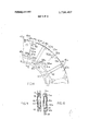
- FIG. 1 is a side view of part of a friction member in accordance with the present invention
- FIG. 2 is a cross-sectional view on the line AA of FIG. 1;
- FIG. 3 is a diagrammatic representation of the forces acting on inner layer 8 of element 2;
- FIG. 4 is a triangle of forces (not to scale) for the force distribution shown in FIG. 3;
- FIG. 5 is a diagrammatic representation of the forces acting on the outer layers 7 of element 4.
- FIG. 6 is a side view of part of another friction member in accordance with the present invention.
- FIG. 7 is a cross-sectional view on the line BB of Figure
- FIG. 8 is a side view of part of a further friction member in accordance with the present invention.
- FIG. 9 is a cross-sectional view on the line D-D of FIG. 8;
- FIG. 10 is a view in the direction of arrow C in FIG. 8 of insert 54;
- FIG. 11 is a diagrammatic representation forces acting on inner layer 47 of element 41;
- FIG. 12 is a diagrammatic representation forces acting on outer layer 46 of element 43;
- FIG. 13 is the triangle of forces (not to scale) for the force distribution shown in FIG. 12;
- FIG. 14 is a side view of part of a still further friction member in accordance with the present invention.
- FIG. 15 is a cross-sectional view on the line E-E of FIG. 14;
- FIG. 16 is a side view of part of a still further friction member in accordance with the present invention.
- FIG. 17 is a cross-sectional view on the line FF of FIG. 16 showing an element comprising a one-piece load-bearing portion (friction pad securing rivet omitted);
- FIG. 18 is a cross-sectional view on the line FF of FIG. 16 showing an element comprising a composite load-bearing portion;
- FIG. 19 is a side view of part of a still further friction member in accordance with the present invention.
- FIG. 20 is a cross-sectional view on the line GG of FIG. 19 showing an element comprising a one-piece load-bearing portion (friction pad securing rivet omitted), and
- FIG. 21 is a cross-sectional view on the line GG of FIG. 19 showing an element comprising a composite load-bearing portion.
- FIG. 1 shows a side view of part of an annular friction member in accordance with the present invention for use as a rotor in a multi-plate aircraft disc brake.
- the friction member 1 is made up of a plurality of substantially segmental-shaped elements, generally designated fro example 2, 3, 4, each element having a three-layer construction comprising two principal loadcarrying outer layers 5, 6 and 7 and a circumferentially displaced relatively low load-carrying inner layer 8, 9 and 10 (see FIG. 2). With this type of construction the outer layers of each element overlap the inner layer of the circumferentially adjacent element.
- the two outer principal load-carrying layers of each element are formed from a relatively strong material such as steel, while the inner layer may be utilized principally as a heat sink and formed from a material with a higher thermal capacity such as beryllium or a carbon or boron composition. Circumferentially adjacent inner layers are spaced from each other to allow for manufacturing inaccuracies and the effect of thermal expansion under braking.
- Both the outer layers of each element may carry friction pads 27, omitted from FIG. 1 for clarity, on their of the of the axially outer sides, or alternatively only one outer layer, or in some cases neither outer layer, may carry a friction pad.
- the outer layers are also provided with cut outs 11,12 to engage support means in the form of keys (not shown) which extend in a direction parallel to the axis of the annular friction member, the support means being associated with a rotatable portion of the associated aircraft wheel.
- the two outer layers of each element are rivetted 13,14, or secured in any other suitable manner, to a retaining ring 16 at a position adjacent their inner peripheries.
- each element is provided with abutment surfaces 17,18: 19:20 arranged to engage corresponding surfaces on abutments 21,22 formed on the retaining ring 16.
- each element is secured to the inner layer of each respective element and the circumferentially adjacent element at positions adjacent the outer peripheries of the inner layers by rivets 23,24: 25,26.
- the force X acting on inner layer 8 tends to rotate inner layer 8 in a clockwise direction. This tendency being resisted by forces X, and X exerted on inner layer 8 by rivets 23 and 26 (see FIG. 3).
- the forces acting on inner layer 8 must intersect at a point and on considering the diagrammatic representation of the forces acting on inner layer 8, shown in FIG. 3, it can be seen that for equilibrium the point of intersection of the rivet forces X,, X, and communicated force X must be on the line of action 30 of X.
- FIG. 4 shows the triangle of forces for inner layer 8 and illustrates, in dotted detail 33 and 34, the manner in which the forces exerted by rivets 23 and 26 must increase in order to maintain equilibrium, for a given magnitude of X, as rivets 23 and 26 are positioned closer to the axis of symmetry 31, as shown by dotted detail 35 and 36 in FIG. 3.
- rivets 23 and 26 This clearly demonstrates the desirability of spacing rivets 23 and 26 as far apart as possible in order to allow the inner layer to be formed from a structurally weaker material.
- the wide spacing of rivets 23 and 26 also has the advantage of bringing the pairs of rivets 26,25: 24,23 in each outer layer of the rotor closer together which assists in minimizing the shear loading exerted on these pairs of rivets due to the heat shrinkage of the outer layers.
- FIGS. 6 and 7 show a friction member in accordance with the present invention for use as a stator in a multiplate aircraft disc brake.
- the elements are arranged to engage support means in the form of axially extending keyways 29 at their inner peripheries.
- the friction elements are otherwise substantially identical in construction with the elements shown in FIGS. 1 and 2 and like or equivalent components and forces have therefore been indicated with the same numerals with a suffix a added.
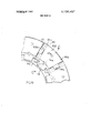
- FIGS. 8 and 9 show a further example of part of a friction member 40 in accordance with the present invention for use as a rotor in a multi-plate aircraft disc brake.
- the friction member is made up of a plurality of substantially sector-shaped elements generally designated for example 41,42,43 each element having a three-layer construction comprising two principal loadcarrying outer layers 44,45,46 and a circumferentially displaced relatively low load-carrying inner layer 47,48 amd 49.
- the outer layers of each element overlap the inner layer of the circumferentially adjacent element and the outer principal load-carrying layers of each element are.
- Inserts 53 and 54 are in turn arranged to engage support means in the form of keys (not shown) associated with a rotatable portion of the associated aircraft wheel. Rivets 55 and 56 secure inserts 53 and 54 in position, each insert being provided with two pairs of ears 57,58: 59,60 (see FIG. which abut the sides of the associated cut out and transmit torque directly from the inserts to the outer layers of the elements.
- each element The two outer layers of each element are rivetted 61,62 or otherwise secured to a retaining ring 63 at their inner peripheries.
- the radially inner corners of each inner layer of each element are chamfered to provide inclined abutment surfaces 64,65: 66,67 which are arranged to engage corresponding abutment surfaces on circumferentially spaced abutments 68,69 formed on retaining ring 63.
- the radially outer corners of each inner layer of each element are also chamfered to provide inclined abutment surfaces 70,71: 72:73 which are arranged to engage corresponding abutment surfaces on inserts 53,54.
- each inner layer is located at each corner relative to the circumferentially adjacent outer layers without being directly secured thereto.
- the rivets used in the element construction shown in FIGS. 8 and 9 are countersunk into the inner layer so as to increase the cross-sectional area of material subjected to shear at the inner and outer layer interfaces.
- This rivet countersinking technique can also be used on any of the other composite element constructions disclosed in this application.
- outer layers 46 of element 43 are subjected to the same resultant frictional force F and reaction R as the element 4 shown in FIG. 1.
- outer layers 46 also tend to rotate in a clockwise direction when the rotor is subjected to braking forces while spinning in a clockwise direction.
- This tendency to rotate in a clockwise direction is transmitted to ring 63 via rivet 62 causing ring 63 to move slightly in an anticlockwise direction to make abutting contact with surfaces 65,66, etc. on inner layers 47,48, etc.
- the tendency of the outer layers 46 of element 43 to rotate is communicated to inner layer 47 as a force Y acting at right angles to abutment face 65 (see FIG. 11).
- the inner layer 47 therefore tends to rotate clockwise slightly thereby generating a reaction force from insert 53 acting on abutment face 70.
- abutment faces 65 and 70 By arranging diagonally opposite abutment faces 65 and 70 to be parallel to each other the magnitudes of Y and the reaction force Y generated at abutment face 70 can be made of equal magnitude and also arranged to have the same line of action though acting in opposite senses (see FIG. 11). Hence the tendency of outer layer 46 to rotate in a clockwise direction is resisted by placing inner layer 47 in compression across surfaces and 70.
- FIGS. 14 and 15 show another form of friction member in accordance with the present invention for use as a stator in a multi-plate aircraft disc brake.
- the friction member elements are arranged to engage support means in the form of axially extending keyways 80 at their inner peripheries by rivetting the outer layers of each element to a ring 81 provided with radially inwardly projecting tongues 82 arranged to engage keyways 80.
- the friction elements of the friction member shown in FIGS. 14 and 15 are otherwise substantially identical to the construction of the elements shown in FIGS. 8 and 9 and like or equivalent components and forces have therefore been indicated with the same numerals with the suffix a added.
- FIGS. 16-18 show a further alternative form of the present invention, as applied to aircraft disc brake rotors, in which the circumferentially overlapping kind of element described above is not employed.
- each element comprises asubstantially segmental-shaped load-bearing portion generally designated 86 which may be a one-piece construction (see FIGS. 17) of steel or other suitable material or alternatively may again be a three-layer construction (see FIG. 18) in which the inner layer 87 is a high thermal capacity structurally weaker material and the outer principal load-carrying layers 88 are formed from steel or other suitable material.
- Each load bearing portion carries a friction pad 89 on one, both or neither axially outer sides depending on the design of the brake for which the element is intended. The friction pad or pads may be secured to the load bearing portion by rivetting 93 or any other suitable means. 7
- Each element is provided with a cut-out or cut-outs 90, depending on whether a one-piece load-bearing portion is adopted, to engage support means in the form of keys (not shown) in the manner previously described with reference to the FIGS. 1 and 8.
- Each element 6 is also secured at a position adjacent its inner periphery to a retaining ring or rings 91 by means of a rivet 90.
- FIG, 17 shows the manner in which two axially spaced rings set into circumferentially extending grooves in the side faces of a' one-piece load-bearing portion can be utilized in place of a single ring.
- each element rotates under braking torque, previously described above, is resisted by providing each element with a circumferentially extending tongue 94, or other suitable interconnecting means, on one radially extending face and a slot 95, or other corresponding suitable interconnecting means, on the other radially extending face to receive the corresponding circumferentially extending tongue, or other interconnecting means of the adjacent element.
- the rotor elements shown in FIG. 16 tend to rotate in a clockwise manner under the action of the resultant frictional force F and support reaction R when the rotor is subjected to braking forces while rotating in a clockwise direction.
- adjacent radially extending faces of adjacent elements are attempting to move in opposite directions; the faces of the elements provided with tongues in FIG. 16 attempting to move radially inwardly and the other faces of the elements provided with cut outs attempting to move radially outwardly.
- the tongue of each element experiences an upward force from the cut-out of the adjacent element and the cut-out of each element experiences a downward force from the tongue of the adjacent element.
- FIGS. 19-21 show a still further form of the present invention, as applied to an aircraft disc brake stator, in which the elements 100 are arranged to engage support means in the form of axially extending keyways 101 at their inner peripheries.
- the friction elements are otherwise substantially identical in construction with the elements shown in FIGS. 16-18 and like or equivalent components and forces have been indicated with the same numerals with a suffix a.
- An annular friction member for use in a disc brake or like friction mechanism, a plurality of interconnected substantially segmental-shaped friction elements, each element being arranged to be operatively associated with either a rotatable or nonrotatable portion of the disc brake or friction mechanism, each of the friction elements having a single attachment to said retaining ring to provide unrestricted thermal expan sion and thermal shrinkage independently of said retaining ring which is proportioned to extend adjacent one of the peripheries of the elements, and each such frictional element comprising a pair of principal loadcarrying outer layers and an inner layer sandwiched therebetween, the inner layer of each element being circumferentially displaced relative to the outer layers of the element so that the outer layers of each element also overlap the innerlayer of the circumferentially ad- 20 jacent element, the outer layers of each of the friction elements being secured to a retaining ring arranged to extend adjacent one of the peripheries of the elements, the retaining ring arranged to communicate the tendency of the two outer layers of each element
- a friction member according to claim 1 wherein the corners of the inner layers of the elements are chamfered to engage corresponding abutment surfaces on the ring and inserts, the angle of chamfer of diagonally opposite corners of the inner layers being equal so that the diagonally opposite abutment faces so formed on the inner layers are parallel.
- a friction member according to claim wherein rotatable or nonrotatable portions of the disc brake or friction mechanisms have inserts arranged to engage therewith.
Landscapes
- Engineering & Computer Science (AREA)
- General Engineering & Computer Science (AREA)
- Mechanical Engineering (AREA)
- Braking Arrangements (AREA)
Applications Claiming Priority (1)
| Application Number | Priority Date | Filing Date | Title |
|---|---|---|---|
| GB175970 | 1970-01-14 |
Publications (1)
| Publication Number | Publication Date |
|---|---|
| US3738457A true US3738457A (en) | 1973-06-12 |
Family
ID=9727486
Family Applications (1)
| Application Number | Title | Priority Date | Filing Date |
|---|---|---|---|
| US00104987A Expired - Lifetime US3738457A (en) | 1970-01-14 | 1971-01-08 | Friction mechanisms |
Country Status (4)
| Country | Link |
|---|---|
| US (1) | US3738457A (enExample) |
| DE (1) | DE2101019C3 (enExample) |
| FR (1) | FR2075491A5 (enExample) |
| GB (1) | GB1330891A (enExample) |
Cited By (5)
| Publication number | Priority date | Publication date | Assignee | Title |
|---|---|---|---|---|
| US3934686A (en) * | 1972-12-20 | 1976-01-27 | Dunlop Limited | Carbon friction members having torque transmitting formations |
| US4600090A (en) * | 1983-08-22 | 1986-07-15 | Wabco Fahrzeugbremsen Gmbh | Brake lining support in disc brakes |
| US5868233A (en) * | 1997-02-19 | 1999-02-09 | The Montalvo Corporation | Modular brakes with replaceable friction pads |
| US6062348A (en) * | 1997-12-04 | 2000-05-16 | Atkinson, Jr.; John H. | Rapidly-deployable vehicle snow chain system having individually-replaceable interlocking chain attachment plates |
| US20070144840A1 (en) * | 2005-12-23 | 2007-06-28 | Brembo Ceramic Brake Systems S.P.A. | Disc for Disc Brakes |
Families Citing this family (2)
| Publication number | Priority date | Publication date | Assignee | Title |
|---|---|---|---|---|
| CA1174988A (en) * | 1981-01-24 | 1984-09-25 | Takeshi Kawaguchi | Disc brake for motorcycles |
| GB2119879B (en) * | 1982-04-27 | 1986-03-19 | Lucas Ind Plc | Disc brakes |
Citations (5)
| Publication number | Priority date | Publication date | Assignee | Title |
|---|---|---|---|---|
| US3371749A (en) * | 1966-04-20 | 1968-03-05 | Rech Etudes Prod | Segmented disc brake |
| US3422936A (en) * | 1966-05-05 | 1969-01-21 | Hispano Suiza Lallemant Soc | Sector type friction brake disc |
| US3426871A (en) * | 1967-06-08 | 1969-02-11 | Bendix Corp | Laminated segmented rotor |
| US3599766A (en) * | 1969-09-02 | 1971-08-17 | Goodrich Co B F | Segmented friction member for brake or clutch |
| US3613851A (en) * | 1969-08-04 | 1971-10-19 | Goodrich Co B F | Segmented friction member for brake or clutch |
-
1970
- 1970-12-29 GB GB175970*[A patent/GB1330891A/en not_active Expired
-
1971
- 1971-01-08 US US00104987A patent/US3738457A/en not_active Expired - Lifetime
- 1971-01-11 DE DE2101019A patent/DE2101019C3/de not_active Expired
- 1971-01-13 FR FR7100946A patent/FR2075491A5/fr not_active Expired
Patent Citations (5)
| Publication number | Priority date | Publication date | Assignee | Title |
|---|---|---|---|---|
| US3371749A (en) * | 1966-04-20 | 1968-03-05 | Rech Etudes Prod | Segmented disc brake |
| US3422936A (en) * | 1966-05-05 | 1969-01-21 | Hispano Suiza Lallemant Soc | Sector type friction brake disc |
| US3426871A (en) * | 1967-06-08 | 1969-02-11 | Bendix Corp | Laminated segmented rotor |
| US3613851A (en) * | 1969-08-04 | 1971-10-19 | Goodrich Co B F | Segmented friction member for brake or clutch |
| US3599766A (en) * | 1969-09-02 | 1971-08-17 | Goodrich Co B F | Segmented friction member for brake or clutch |
Cited By (5)
| Publication number | Priority date | Publication date | Assignee | Title |
|---|---|---|---|---|
| US3934686A (en) * | 1972-12-20 | 1976-01-27 | Dunlop Limited | Carbon friction members having torque transmitting formations |
| US4600090A (en) * | 1983-08-22 | 1986-07-15 | Wabco Fahrzeugbremsen Gmbh | Brake lining support in disc brakes |
| US5868233A (en) * | 1997-02-19 | 1999-02-09 | The Montalvo Corporation | Modular brakes with replaceable friction pads |
| US6062348A (en) * | 1997-12-04 | 2000-05-16 | Atkinson, Jr.; John H. | Rapidly-deployable vehicle snow chain system having individually-replaceable interlocking chain attachment plates |
| US20070144840A1 (en) * | 2005-12-23 | 2007-06-28 | Brembo Ceramic Brake Systems S.P.A. | Disc for Disc Brakes |
Also Published As
| Publication number | Publication date |
|---|---|
| DE2101019A1 (de) | 1971-12-30 |
| DE2101019B2 (de) | 1979-09-20 |
| DE2101019C3 (de) | 1980-06-04 |
| GB1330891A (en) | 1973-09-19 |
| FR2075491A5 (enExample) | 1971-10-08 |
Similar Documents
| Publication | Publication Date | Title |
|---|---|---|
| US3198295A (en) | Friction couple cooling device | |
| US4878563A (en) | Brake apparatus | |
| US3613851A (en) | Segmented friction member for brake or clutch | |
| US3972393A (en) | Friction pad and support for a disc brake | |
| US3895693A (en) | Disc-brakes with graphite friction linings | |
| US3759354A (en) | Brake disc structure | |
| US3738457A (en) | Friction mechanisms | |
| US3907076A (en) | Key slot segments for driving brake discs | |
| US3425524A (en) | Brake disc structure | |
| US3295641A (en) | Wheels | |
| US2893519A (en) | Brake assembly | |
| US3250349A (en) | Disc brake | |
| US3605968A (en) | Segmented friction member for brake or clutch | |
| US5085295A (en) | Brake rotor and stator discs with multiple rings joined by pins | |
| US3764230A (en) | Articulated helicopter rotor utilizing plural elastomeric bearings for articulated support of the blade from the rotor hub | |
| US3807534A (en) | Friction disc | |
| JPH0356330B2 (enExample) | ||
| US3599766A (en) | Segmented friction member for brake or clutch | |
| US3483953A (en) | Disc element construction for disc brake | |
| GB1112906A (en) | Improvements in or relating to disc brakes | |
| US3456768A (en) | Disc element construction for disc brake | |
| US4290505A (en) | Pin centered brake | |
| US3726374A (en) | Circular segmented friction member for brake or clutch | |
| US3430741A (en) | Disc brakes | |
| US4013147A (en) | Segmented friction disc for brakes |