US373676A - Ventilator - Google Patents
Ventilator Download PDFInfo
- Publication number
- US373676A US373676A US373676DA US373676A US 373676 A US373676 A US 373676A US 373676D A US373676D A US 373676DA US 373676 A US373676 A US 373676A
- Authority
- US
- United States
- Prior art keywords
- head
- tube
- ventilator
- elbow
- secured
- Prior art date
- Legal status (The legal status is an assumption and is not a legal conclusion. Google has not performed a legal analysis and makes no representation as to the accuracy of the status listed.)
- Expired - Lifetime
Links
- 239000002184 metal Substances 0.000 description 3
- 241000511582 Actinomyces meyeri Species 0.000 description 2
- 239000003818 cinder Substances 0.000 description 1
- 238000010276 construction Methods 0.000 description 1
- 239000000428 dust Substances 0.000 description 1
- 239000010985 leather Substances 0.000 description 1
- 239000000463 material Substances 0.000 description 1
- 239000005060 rubber Substances 0.000 description 1
Images
Classifications
-
- F—MECHANICAL ENGINEERING; LIGHTING; HEATING; WEAPONS; BLASTING
- F23—COMBUSTION APPARATUS; COMBUSTION PROCESSES
- F23L—SUPPLYING AIR OR NON-COMBUSTIBLE LIQUIDS OR GASES TO COMBUSTION APPARATUS IN GENERAL ; VALVES OR DAMPERS SPECIALLY ADAPTED FOR CONTROLLING AIR SUPPLY OR DRAUGHT IN COMBUSTION APPARATUS; INDUCING DRAUGHT IN COMBUSTION APPARATUS; TOPS FOR CHIMNEYS OR VENTILATING SHAFTS; TERMINALS FOR FLUES
- F23L17/00—Inducing draught; Tops for chimneys or ventilating shafts; Terminals for flues
- F23L17/02—Tops for chimneys or ventilating shafts; Terminals for flues
- F23L17/10—Tops for chimneys or ventilating shafts; Terminals for flues wherein the top moves as a whole
Definitions
- the object of my invention is to produce a 4ventilator particularly applicable to steamcars, but which can also be employed in ventilating buildings and other places, or as a chimney-cowl.
- Figure l represents a side elevation of a ventilator embodying my invention.
- Fig. 2 is a front view of the same, and
- Fig. 3 is a longitudinal vertical section taken on line x :o of Fig. 2.
- Fig. l represents a vertical section of the ventilator, with holes in the tube for creating greater draft.
- A is a metal tube provided at its lower end with a collar, ll.
- this collar is shown as a flat piece of metal secured to the tube A at an angle of ninety degrees; but f of course the shape of the collar and base of the tube will have to be modified according to the place and position the ventilator is to oc cupy.
- the upper end of the tube A is turned inward and wired, as shown at a, Fig. 3, and at a suitable distance from the upper edge is provided a recess, b.
- C is the head of the ventilator, preferably formed rounding at the top and flat on its lower side, which, however, is rounded out toward the front to form around flaring mouth, D.
- the rear of the head is partly closed by a cover, E, to prevent the entrance of cinders, dust, ttc.
- an elbow, E projecting upward and opening out toward the rear of the head, and to the under side of the bottom is secured a tube, G, the lower end of which is turned in ward and wired, as shown at g, Fig. 3. It will be seen that the projecting portion g of the tube G lits loosely into the depression b,
- H is a ring of leather, rubber, metal, or other suitable material secured onto the lower side of the head C, and rests upon the top of be blown so as to enter the rear of the venti-l lator-head they will be prevented from enterA ing the elbow F.
- a wing, J, or other device for keeping the ventilaton head in proper position to the wind.
Landscapes
- Engineering & Computer Science (AREA)
- Chemical & Material Sciences (AREA)
- Combustion & Propulsion (AREA)
- Mechanical Engineering (AREA)
- General Engineering & Computer Science (AREA)
- Duct Arrangements (AREA)
- Ventilation (AREA)
- Building Environments (AREA)
Description
(No Model.) Y l A. A. MEYER.
VBNTI'LATOR. No. 373,676. Patented NOV.22,1887.
UNITED STATES PATENT Enron,
ANDREIV A. MEYER, OE
BGSTON, MASSACHUSETTS.
VENTI LATOR.
PECIPICATION forming part of Letters Patent No. 373,676, dated November 22, 1887.
Application filed January 13, 1887. Serial No. 224,300.
(No model.)
.To o/ZZ whom t may concern.-
Be it known that I, ANDREW A. MEYER, a citizen of the United States, residing at Boston, in the county of Suffolk and State of Massachusetts, have invented a new. and useful Improvement in Ventilators, of which the following is a specification.
The object of my invention is to produce a 4ventilator particularly applicable to steamcars, but which can also be employed in ventilating buildings and other places, or as a chimney-cowl.
The invention consists in certain details of construction, hereinafter fully set forth, and pointed out in the claim.
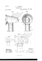
Referring to the accompanying drawings, Figure l represents a side elevation of a ventilator embodying my invention. Fig. 2 is a front view of the same, and Fig. 3 is a longitudinal vertical section taken on line x :o of Fig. 2. Fig. l represents a vertical section of the ventilator, with holes in the tube for creating greater draft. Y
A is a metal tube provided at its lower end with a collar, ll. In the drawings this collar is shown as a flat piece of metal secured to the tube A at an angle of ninety degrees; but f of course the shape of the collar and base of the tube will have to be modified according to the place and position the ventilator is to oc cupy.
The upper end of the tube A is turned inward and wired, as shown at a, Fig. 3, and at a suitable distance from the upper edge is provided a recess, b.
C is the head of the ventilator, preferably formed rounding at the top and flat on its lower side, which, however, is rounded out toward the front to form around flaring mouth, D. The rear of the head is partly closed by a cover, E, to prevent the entrance of cinders, dust, ttc. To the bottoni of the head C is secured an elbow, E, projecting upward and opening out toward the rear of the head, and to the under side of the bottom is secured a tube, G, the lower end of which is turned in ward and wired, as shown at g, Fig. 3. It will be seen that the projecting portion g of the tube G lits loosely into the depression b,
formed in the tube A, so that while'the tube G is free to revolve around the tube A it cannot be drawn off except by unusual force.
H is a ring of leather, rubber, metal, or other suitable material secured onto the lower side of the head C, and rests upon the top of be blown so as to enter the rear of the venti-l lator-head they will be prevented from enterA ing the elbow F.
On the top of the head is secured a wing, J, or other device for keeping the ventilaton head in proper position to the wind.
In operation, supposing the ventilator is applied toa car, the flaring mouth will stand facing the direction in which the train is moving and a strong draft of air will pass through the head in the direction of the arrows marked l, thereby creating a partial vacuum in the elbow F and causing the vitiated air in the car to ascend and pass out in the direction of the arrows marked 2.
If a very strong draft is required, instead of making a recess as shown in Figs. l, 2, and 3, I make a recess as shown in Fig. 4, and provide a series of holes round its upper edge, as shown at o', so that atmospheric air may pass into the tube in the direction of the arrows 3 and escape with the vitiated air out of the head C. This arrangement is particularly applicable when the ventilator is applied to buildings.
What I claim as my invention is- In a ventilator, the combination of the revolving head C, the elbow F, and cover E, the lower edge ofthe elbow being above the lower edge of the cover, substantially as and for the purposes set forth.
In testimony whereof I have signed my name to this specification in thc presence of two subscribing witnesses.
ANDREW A. MEYER.
Vi tnesses:
L. NV. HowEs,
E. PLANTA..
Publications (1)
| Publication Number | Publication Date |
|---|---|
| US373676A true US373676A (en) | 1887-11-22 |
Family
ID=2442686
Family Applications (1)
| Application Number | Title | Priority Date | Filing Date |
|---|---|---|---|
| US373676D Expired - Lifetime US373676A (en) | Ventilator |
Country Status (1)
| Country | Link |
|---|---|
| US (1) | US373676A (en) |
-
0
- US US373676D patent/US373676A/en not_active Expired - Lifetime
Similar Documents
| Publication | Publication Date | Title |
|---|---|---|
| US622375A (en) | Joseph leather | |
| US891967A (en) | Ventilator. | |
| US116049A (en) | Improvement in ventilators | |
| US432395A (en) | Automatic ventilator | |
| US195039A (en) | Improvement in ventilators | |
| US174237A (en) | Improvement in ventilators for chimneys | |
| US162261A (en) | Improvement in ridge-ventilators | |
| US638503A (en) | Ventilator. | |
| US384184A (en) | Weight | |
| US756057A (en) | Hood or injector for car-ventilators. | |
| US1097387A (en) | Ventilator. | |
| US260564A (en) | Hermann hahn | |
| US778554A (en) | Chimney-cowl. | |
| US441236A (en) | Chimney-cowl | |
| US6449A (en) | Chimney-cap | |
| US710350A (en) | Ventilator. | |
| US1275211A (en) | Ventilator. | |
| US901085A (en) | Wind-actuated ventilator. | |
| US499008A (en) | Window | |
| US830749A (en) | Ventilating device. | |
| US391902A (en) | Ventilator | |
| US265814A (en) | Ventilator or chimney-cap | |
| US183848A (en) | Improvement in ventilators | |
| US1133350A (en) | Air-heater. | |
| US1124805A (en) | Ventilator. |