US3735936A - Web separating device - Google Patents
Web separating device Download PDFInfo
- Publication number
- US3735936A US3735936A US00167195A US3735936DA US3735936A US 3735936 A US3735936 A US 3735936A US 00167195 A US00167195 A US 00167195A US 3735936D A US3735936D A US 3735936DA US 3735936 A US3735936 A US 3735936A
- Authority
- US
- United States
- Prior art keywords
- web
- cartridge
- slot
- enclosure
- webs
- Prior art date
- Legal status (The legal status is an assumption and is not a legal conclusion. Google has not performed a legal analysis and makes no representation as to the accuracy of the status listed.)
- Expired - Lifetime
Links
- 230000000694 effects Effects 0.000 claims description 6
- 238000000926 separation method Methods 0.000 claims description 3
- 238000003780 insertion Methods 0.000 abstract description 6
- 230000037431 insertion Effects 0.000 abstract description 6
- 239000000839 emulsion Substances 0.000 description 8
- 238000004804 winding Methods 0.000 description 4
- 230000001681 protective effect Effects 0.000 description 2
- 230000005855 radiation Effects 0.000 description 2
- 239000000463 material Substances 0.000 description 1
- 238000000034 method Methods 0.000 description 1
- 238000012986 modification Methods 0.000 description 1
- 230000004048 modification Effects 0.000 description 1
- 229920000136 polysorbate Polymers 0.000 description 1
Images

Classifications
-
- G—PHYSICS
- G03—PHOTOGRAPHY; CINEMATOGRAPHY; ANALOGOUS TECHNIQUES USING WAVES OTHER THAN OPTICAL WAVES; ELECTROGRAPHY; HOLOGRAPHY
- G03B—APPARATUS OR ARRANGEMENTS FOR TAKING PHOTOGRAPHS OR FOR PROJECTING OR VIEWING THEM; APPARATUS OR ARRANGEMENTS EMPLOYING ANALOGOUS TECHNIQUES USING WAVES OTHER THAN OPTICAL WAVES; ACCESSORIES THEREFOR
- G03B17/00—Details of cameras or camera bodies; Accessories therefor
- G03B17/28—Locating light-sensitive material within camera
- G03B17/30—Locating spools or other rotatable holders of coiled film
-
- G—PHYSICS
- G03—PHOTOGRAPHY; CINEMATOGRAPHY; ANALOGOUS TECHNIQUES USING WAVES OTHER THAN OPTICAL WAVES; ELECTROGRAPHY; HOLOGRAPHY
- G03B—APPARATUS OR ARRANGEMENTS FOR TAKING PHOTOGRAPHS OR FOR PROJECTING OR VIEWING THEM; APPARATUS OR ARRANGEMENTS EMPLOYING ANALOGOUS TECHNIQUES USING WAVES OTHER THAN OPTICAL WAVES; ACCESSORIES THEREFOR
- G03B27/00—Photographic printing apparatus
- G03B27/02—Exposure apparatus for contact printing
- G03B27/14—Details
- G03B27/28—Edge-masking devices
Definitions
- ABSTRACT An enclosure is adapted to receive a cartridge in which first and second webs are wound in substantially contiguous relation on a common core, the cartridge being provided with an opening through which such webs can be advanced.
- the enclosure includes a wall member in which a web egress slot is disposed and a projecting member which is engageable with a corresponding member of the cartridge.
- the cartridge When so engaged, the cartridge will be oriented within the enclosure in a manner such that if the first and second webs are advanced from the cartridge opening, the first web will be positioned for movement through the web egress slot, and the second web will be positioned to abut against the wall member of the enclosure and thus separate from the first web upon movement of the first web through the web egress slot.
- the periphery of the web egress slot is shaped to support the opposed edges of the first web while maintaining a spaced relation with at least one of the web faces.
- the wall member includes an open-ended guideway which communicates with the slot so that such web end can be readily directed into the slot.
- the present invention relates to a device for separating two or more webs, such as a photographic filmstrip and a radiation protective backing web, which are disposed in substantially contiguous relation. More particularly, this invention relates to a web separating device wherein the contiguously disposed webs, to be separated, are wound on a common core within a cartridge.
- Known apparatus of this kind such as the device disclosed in U.S. Pat. No. 751,553, generally includes an enclosure which is adapted to receive the web roll and in which the web roll is intended to be rotatably supported.
- the enclosure is provided with a web egress slot or opening through which a first of the webs may be advanced upon unwinding from a web roll supported in the enclosure.
- the second or remaining web is either collected within the enclosure or diverted elsewhere by a suitable guide member of the enclosure.
- web separating devices substantially of the foregoing configuration are particularly suited for separating an exposed filmstrip on which is recorded a latent image and a paper backing web which is contiguously disposed along the base side of such filmstrip to shield the filmstrip from unintentional exposure to light.
- the two webs are wound together on a common core so as to effect a web roll which comprises successive, alternate convolutions of filmstrip and backing web.
- the web roll is best handled in a darkened environment to minimize the possibility of unintentional exposure, difficulty will be encountered in orienting a free leading end of the filmstrip for insertion into the web egress slot should the web roll be rotatably supported in the enclosure.
- the web egress slot is generally of cross-sectional dimensions slightly greater than the corresponding dimensions of the filmstrip, difficulty will be encountered in inserting the leading filmstrip end into such slot without the presence of visually assisting light.
- Another object of the present invention is to provide an improved web separating device which is adapted for use with a cartridge in which at least two contiguously disposed webs are wound on a common core.
- an enclosure adapted to receive a cartridge in which first and second webs are wound in substantially contiguous relation on a common core.
- the cartridge is provided with an opening through which the first and second webs can be advanced.
- the enclosure includes a wall member in which a web egress slot is disposed and a projecting member which is engageable with a corresponding member of the cartridge.
- the cartridge When so engaged, the cartridge will be oriented within the enclosure in a manner such that if the first and second webs are advanced from the cartridge opening, the first web will be positioned for movement through the web egress slot, and the second web will be positioned to abut against the wall member of the enclosure and thus separate from the first web upon movement of the first web through the web egress slot.
- the periphery of the web egress slot is shaped to support the opposed edges of the first web while maintaining a spaced relation with at least one of the web faces. Accordingly, at least one face of the first web is prevented from abutting against,
- the wall member includes an open-ended guideway which communicates with the slot so that such web end can be readily directed into the slot.
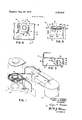
- FIG. 2 is a perspective front view of a web separating device, according to a preferred embodiment of the present invention, and a take-up chamber of the cartridge depicted in FIG. 1;
- FIG. 3 is a top plan view of the web separating device as depicted in FIG. 2;
- FIG. 4 is a cross-sectional elevation view of the web separating device and the take-up chamber of the cartridge, showing such chamber supported in the web separating device and the manner in which the filmstrip and the backing web are separated;
- FIG. is a side elevation view of the web separating device as depicted in FIG. 4, showing the manner in which a free leading end portion of the filmstrip is inserted in a web egress slot of the web separating device;
- FIG. 6 is a cross-sectional elevation view of the web separating device and the take-up chamber of the cartridge, showing the manner in which the web separating device is adapted to prevent improper receipt of such chamber.
- FIG. 1 a cartridge with which such device is adapted to be used.
- a cartridge with which such device is adapted to be used.
- this cartridge 1 is provided with a contiguously disposed filmstrip 2 and paper backing web 3 which are wound together in a convoluted manner, within the cartridge, such that successive convolutions are alternately formed by filmstrip and backing web portions.
- the filmstrip 2 is not attached to the backing web 3 but rather is simply in frictional contact with such web. Since the backing web 3 is intended to shield the the filmstrip 2 from unintentional exposure to light via a rectangular aperture 4 in the cartridge 1, the filmstrip and the backing web are wound so that the outermost convolution is formed by a backing web portion.
- a substantial length of the filmstrip 2 and a corresponding length of paper backing web 3 are wound together in a supply chamber 5 of the cartridge, with leading portions of the filmstrip and the backing web secured about a winding core 6 rotatably supported within a take-up chamber 7 of the cartridge.
- the filmstrip 2 and the backing web 3 will be simultaneously drawn out of the supply chamber 5, through an intermediate guide chamber 8, and thence into the take-up chamber 7. Accordingly, a web roll comprising successive alternate convolutions of the filmstrip 2 and the backing web 3 will be formed about the winding core 6, with the outermost convolution being formed by a backing web portion.
- the cartridge 1 should now be broken apart or severed, by any suitable mechanism, transversely across the intermediate guide chamber 8 so as to separate the supply and take-up chambers 5 and 7 in the manner shown in FIG. 1, it will then be possible to draw the filmstrip 2 and the backing web 3 (by their respective free leading end portions 9 and 10) simultaneously off the winding core 6 and out of the take-up chamber.
- the filmstrip 2 is of the kind provided with a base side or face 11 and with an emulsion side or face 12.
- the base side 11 of the filmstrip 2 generally exerts less of a frictional force on a convolution of the paper backing web 3 than the frictional force exerted by the emulsion side 12 of the filmstrip on the same convolution. This is so because the base side 11 is relatively smoother than the emulsion side 12 and because of the clock-spring tendency of the filmstrip 2, when wound, to move the next inwardly succeeding convolution of the backing web 3 into abutment against the emulsion side.
- FIGS. 2 and 3 a web separating device generally designated by the reference number 13.
- This device comprises a box-like enclosure 14 which is adapted to receive the take-up chamber 7 of the cartridge 1, including the commonly wound filmstrip 2 and paper backing web 3 (see FIG. 2).
- the take-up chamber 7 is provided with a recess 15 in which a spindle member 16 of the enclosure 14 can be located for rotatably supporting the take-up chamber within the enclosure.
- the enclosure 14 includes a wall member 17, in which a web egress slot 18 is disposed, and a projecting or tab member 19, which is engageable with an exterior lip member 20 of the take-up chamber 7.
- the take-up chamber 7 When the tab and lip members 19 and 20 are engaged, the take-up chamber 7 will be prevented from rotating within the enclosure 14 in a clockwise direction as viewed in FIG. 4. Moreover, the take-up chamber 7 will be oriented with respect to the web egress slot 18 in a manner such that if the filmstrip 2 and the backing web 3 are advanced from the take-up chamber, and the free leading end portion 9 of the filmstrip 2 is then moved through the web egress slot, the free leading end portion 10 of the backing web 3 will overlap the wall member 17 as shown in FIG. 4. Upon drawing a length 2' of the filmstrip 2 outwardly through the web egress slot 18, a loop 3' of the backing web 3 will be effected, as schematically illustrated in FIG. 4, for the reasons adequately described hereinbefore.
- This loop 3' will abut against a web guide surface 21 of the wall member 17 and thus separate from the filmstrip 2.
- the loop 3' Upon drawing a further length 2" of the filmstrip 2 outwardly through the web egress slot 18, the loop 3' will be enlarged so as to form a loop 3" and will be guided along the web guide surface 21 toward the bottom 22 of the enclosure 14. In this manner, the filmstrip 2 and the backing web 3 will be completely separated, the backing web either collecting within the bottom 22 of the enclosure or, if such bottom is open (not shown), passing from the enclosure into an appropriate receptacle (not shown).
- the tab member 19 of the web separating device 13 and the lip member 20 of the take-up chamber 7 are adapted for engagement when such chamber is oriented, within the enclosure 14, to position the free leading end portion 9 of the filmstrip 2 for insertion into the web egress slot, 18.
- This last-mentioned feature is especially useful in situations where a latent image is recorded on the filmstrip 2, so that the take-up chamber 7 would be best handled in a darkened environment to minimize the possibility of unintentional exposure of the filmstrip to light.
- the periphery of the web egress slot 18 is adapted to provide support for the longitudinal opposed edges of the filmstrip 2 while maintaining a spaced relation with the base and emulsion sides 11 and 12 of the filmstrip. More specifically, the web egress slot 18 comprises two spaced opposed edges or surfaces 23 and 24 and an interconnecting V-shaped edge or surface 25. The two slot edges 23 and 24 serve to support, in a guiding manner, the longitudinal opposed edges of the filmstrip 2, while the particular shape or outline of the web egress slot 18 effects a spaced relation between such slot and the base and emulsion sides 11 and 12 of the filmstrip 2. Accordingly, the emulsion side 12 of the filmstrip 2 is prevented from abutting against, and possibly being scratched by, the web egress slot 18 upon movement of the filmstrip through such slot.
- the wall member 17 of the enclosure 13 includes an open-ended guideway which is defined by angularly disposed surfaces 26,27 and 28, 29 and which communicates with the web egress slot.
- the surfaces 26 and 27 connect with the edge 23 of the web egress slot 18 and the surfaces 28 and 29 connect with the edge 24 of such slot, so as to provide a means for readily directing the free leading end portion 9 of the filmstrip 2 into the web egress slot.
- FIGS. 2, 3 and 6, there is shown a backstop 30 which angularly extends from a guide wall 31 of the enclosure 14.
- the guide wall 31 serves to direct the take-up chamber 7 onto the spindle member 16.
- the backstop 30 is adapted to prevent substantial receipt of the take-up chamber 7 on the spindle member 16 should an attempt be made to incorrectly position such chamber on the spindle member in the manner shown in FIG. 6.
- the web separating device 13 has been considered for use with the filmstrip 2 and the paper backing web 3, it will of course be appreciated that such device can be similarly used with other kinds of web or strip material.
- e. means, engageable with the engageable member of a cartridge so supported, for orienting the cartridge opening with respect to said web egress slot in a manner such that should first and second webs be advanced from the supported cartridge, the first web will be positioned for movement through said slot, and the second web will be positioned to abut against said web guide surface and thus separate from the first web upon movement of the first web through said slot.
- a tab member disposed within said enclosure and adapted to engage the lip member of a supported cartridge upon orientation of the cartridge opening, with respect to said web egress slot, for separation of the first and second webs.
- said enclosure including:
- e. means, engageable with the engageable member of a cartridge so supported, for preventing rota-.
- tion of the supported cartridge in a predetermined direction and for orienting the cartridge opening with respect to said web egress slot in a fining means includes:
- a web separating device as recited in claim 6,
- the first 10 wherein the first web is further provided with a free web will be positioned for movement through leading end, and wherein said enclosure further insaid slot, and the second web will be positioned eludes:
Landscapes
- Physics & Mathematics (AREA)
- General Physics & Mathematics (AREA)
- Sheets, Magazines, And Separation Thereof (AREA)
- Packaging Of Machine Parts And Wound Products (AREA)
- Replacement Of Web Rolls (AREA)
Applications Claiming Priority (1)
| Application Number | Priority Date | Filing Date | Title |
|---|---|---|---|
| US16719571A | 1971-07-29 | 1971-07-29 |
Publications (1)
| Publication Number | Publication Date |
|---|---|
| US3735936A true US3735936A (en) | 1973-05-29 |
Family
ID=22606340
Family Applications (1)
| Application Number | Title | Priority Date | Filing Date |
|---|---|---|---|
| US00167195A Expired - Lifetime US3735936A (en) | 1971-07-29 | 1971-07-29 | Web separating device |
Country Status (4)
| Country | Link |
|---|---|
| US (1) | US3735936A (show.php) |
| DE (1) | DE7228094U (show.php) |
| FR (1) | FR2134065B1 (show.php) |
| GB (1) | GB1402333A (show.php) |
Cited By (1)
| Publication number | Priority date | Publication date | Assignee | Title |
|---|---|---|---|---|
| EP0083873A3 (en) * | 1981-12-31 | 1984-08-29 | EASTMAN KODAK COMPANY (a New Jersey corporation) | Photographic roll film cartridge and film strip assembly |
Citations (4)
| Publication number | Priority date | Publication date | Assignee | Title |
|---|---|---|---|---|
| US2555202A (en) * | 1948-07-16 | 1951-05-29 | Willard C Ormond | Roll film developing tank |
| US2562877A (en) * | 1948-05-12 | 1951-08-07 | Albert W Balluff | Daylight loading roll film developing tank |
| US2692541A (en) * | 1950-11-25 | 1954-10-26 | Lesjak Babette Viktoria | Daylight developing tank for roll film having paper protective strips |
| US2693138A (en) * | 1950-05-11 | 1954-11-02 | Lesjak Michael | Daylight developing tank for roll films having protective paper strips |
-
1971
- 1971-07-29 US US00167195A patent/US3735936A/en not_active Expired - Lifetime
-
1972
- 1972-05-18 FR FR727217771A patent/FR2134065B1/fr not_active Expired
- 1972-07-27 GB GB3517672A patent/GB1402333A/en not_active Expired
- 1972-07-28 DE DE19727228094U patent/DE7228094U/de not_active Expired
Patent Citations (4)
| Publication number | Priority date | Publication date | Assignee | Title |
|---|---|---|---|---|
| US2562877A (en) * | 1948-05-12 | 1951-08-07 | Albert W Balluff | Daylight loading roll film developing tank |
| US2555202A (en) * | 1948-07-16 | 1951-05-29 | Willard C Ormond | Roll film developing tank |
| US2693138A (en) * | 1950-05-11 | 1954-11-02 | Lesjak Michael | Daylight developing tank for roll films having protective paper strips |
| US2692541A (en) * | 1950-11-25 | 1954-10-26 | Lesjak Babette Viktoria | Daylight developing tank for roll film having paper protective strips |
Cited By (1)
| Publication number | Priority date | Publication date | Assignee | Title |
|---|---|---|---|---|
| EP0083873A3 (en) * | 1981-12-31 | 1984-08-29 | EASTMAN KODAK COMPANY (a New Jersey corporation) | Photographic roll film cartridge and film strip assembly |
Also Published As
| Publication number | Publication date |
|---|---|
| GB1402333A (en) | 1975-08-06 |
| DE7228094U (de) | 1972-12-14 |
| FR2134065B1 (show.php) | 1973-07-13 |
| FR2134065A1 (show.php) | 1972-12-01 |
Similar Documents
| Publication | Publication Date | Title |
|---|---|---|
| JPH037932B2 (show.php) | ||
| US3008661A (en) | Antisnubber arrangement for film handling apparatus | |
| US3467340A (en) | Apparatus for and method of feeding strip material | |
| US3695160A (en) | Film cartridge for preventing the end of a filmstrip from entering a cartridge chamber | |
| US1921560A (en) | Film spool for roll film cameras | |
| US3712558A (en) | Take-up device for a strip of web material | |
| US3416427A (en) | Photographic apparatus | |
| US5226613A (en) | Photographic film cassette | |
| US3614012A (en) | Elimination of backing paper shortage in roll film cartridges | |
| US3800306A (en) | Method of operating a film handling cassette | |
| US1469485A (en) | Magazine box for cinematographic or photographic apparatus | |
| US3322366A (en) | Automatic take-up cartridge | |
| US3735936A (en) | Web separating device | |
| US4325624A (en) | Self-developing type film processor kit | |
| US2153149A (en) | Lantern slide | |
| USRE28438E (en) | Ray film package | |
| US3364835A (en) | Photographic apparatus and method | |
| US3183809A (en) | Photographic apparatus for use with image transfer film product | |
| US3698654A (en) | Self-threading take-up device | |
| US3539257A (en) | Document photographing machine | |
| US3662972A (en) | Magazine for a reel of film or the like | |
| US3323744A (en) | Film strip canister | |
| US3722055A (en) | Cartridge opening device | |
| US3480226A (en) | Projection cartridge | |
| US3780922A (en) | Cartridge stripper |