United States Patent Biermann 1 March 6, 1973 TOE IRON FOR SAFETY SKI BINDINGS Primary Examiner-Leo Friaglia [75] Inventor: Peter Biermann, Garmisch-Parten- Assistant 'f' Song kitchen, Germany AttorneyFleit, Gipple & Jacobson [73] Assignee: Hannes Marker, Garmisch-Parten- 57] ABSTRACT kirchen, Germany F] d De 1 1970 A pivoted member carries at least one soleholder and l e c.
Appl. N0.: 93,942
is mounted on a vertical carrying pin that is rigid with a base plate. The pivoted member is movable from its normal position against the force of at least one spring. At least one vertical and preferably flat surface is formed on that half of the carrying pin which is adjacent to the soleholder. A mating surface of the pivoted member is associated with each of said vertical surfaces and engages the same when the pivoted member is in its normal position. The mating surface or surfaces is a portion or are portions of the wall of the bearing of the pivoted member. Said bearing is clear of that half of the carrying pin which is remote from the soleholder when the pivoted member is in its normal position.
8 Claims, 10 Drawing Figures PATENIEUHAR ems 3,719,368
sum 10F a a A Q Q 1L qiim wall/11111111474 may Biermann PATENTEDMR m SHEET 2 [IF 3 PATENTEU 6 SHEET 30F a TOE IRON FOR SAFETY SKI BINDINGS The present invention relates to toe irons for safety ski bindings, which toe irons comprise a pivoted member, which carries at least one soleholder and is mounted on a vertical carrying pin that is rigid with a base plate, the pivoted member being movable from its normal position against the force of at least one spring.
Known toe irons of that type have generally the essential disadvantage that the pivotal member is swung forwardly, toward the tip of the ski from the very beginning of its outward pivotal movement so that the skiing boot which engages the soleholder or soleholders moves forwardly too. Thereafter, an automatic return of the toe iron and the skiing boot to their normal position cannot be ensured within the so-called elastic range usually because the forward movement of the skiing boot has resulted in a relaxation of the spring which acts on the heel and urges the boot against the toe iron. The skiing boot will remain in an oblique position to which it has been moved on the ski by forces which act only as shocks and do not cause a release of the toe iron. The oblique position of the skiing boot prevents a reliable and exact control of the ski and may often result in atypical skiing injuries if the toe iron is subsequently released unexpectedly and for no apparent reason.
In other known toe irons of the kind defined first hereinbefore, a satisfactory return of the skiing boot within the elastic range is ensured because the soleholder is provided with two eccentric teeth, which are impressed into the toe portion of the sole of the skiing boot. During an outward pivotal movement of such toe iron, the trailing tooth moves initially on an arc of a circle slightly to the rear, toward the rear end of the ski, so that a forward movement of the skiing boot is prevented and the toe iron and skiing boot can return to their central position within the elastic range. To ensure that the teeth of the soleholder will reliably hold the skiing boot against a movement transverse to the longitudinal direction of the ski, particularly during an outward pivotal movement within the elastic zone, even when only one of the teeth still engages the toe portion of the sole, it is generally necessary to provide said sole with two notches, which receive the two teeth when the skiing boot is in its normal position. The sole is damaged when these notches are subsequently formed. These toe irons have the additional disadvantage that their exact function will be ensured only when the skier stepping into the binding takes care to see that both teeth are received by the notches of the skiing boot. This is relatively difficult in deep snow or on a hill so that there is again a risk that the skiing boot may assume an oblique position and be improperly held on the ski and there is a great danger of injury caused by -a subsequent fall, which would not be necessary otherwise.
For this reason it is an object of the invention so to improve a toe iron of the kind defined first hereinbefore that the disadvantages of the known toe irons of this kind are avoided in a simple and reliable manner.
In a toe iron for safety ski bindings, which toe iron comprises a pivoted member, which carries at least one soleholder and is mounted on a vertical carrying pin that is rigid with a base plate, the pivoted member being movable from its normal position against the force of at least one spring, the above-mentioned object is accomplished according to the invention in that at least one vertical and preferably flat surface is formed on that half of the carrying pin which is adjacent to the soleholder, a mating surface of the pivoted member is associated with each of said vertical surfaces and engages the same when the pivoted member is in its normal position, the mating surface or surfaces is a portion or are portions of the wall of the bearing of the pivoted member, and said bearing is clear of that half of the carrying pin which is remote from the soleholder when the pivoted member is in its normal position. As a result of this special mounting of the pivoted member on the carrying pin, an outward pivotal movement of the pivoted member will cause the latter to perform not only an angular movement but also a rearward shift relative to the carrying pin so that the soleholder or soleholders is or are moved in this phase along an are which is tangent to or intersects the arc of a circle which is described by the toe portion of the skiing boot and is centered on the axis of rotation of the skiing boot on the ski. This arrangement results in an elastic range in which the skiing boot cannot be shifted forwardly during an outward pivotal movement and in which the toe iron and the skiing boot can easily be returned to their normal position. Besides, the soleholder or soleholders may be designed to engage the toe portion of the skiing boot on a large surface so that the skier can step into this binding much more easily than into one which comprises the above-mentioned toe iron.
The carrying pin will have a simple design if it has only a single vertical flat surface, which extends transversely to the longitudinal direction of the toe iron.
To improve the centering of the pivoted member in its normal position, it has been found desirable to provide the carrying pin with two flat vertical surfaces, which converge toward the soleholder and have a vertex that is disposed in the central vertical longitudinal plane of the toe iron.
In a development of the invention, the mating surface or each of the mating surfaces may be formed with a recess, which is defined by vertical edge lands. The carrying pin can enter the recess or recesses when the pivoted member has performed a pivotal movement through a predetermined angle. During a continued pivotal movement, the pivoted member will no longer be shifted longitudinally at the carrying pin or such longitudinal shift will only be very small so as to ensure an automatic return of the pivoted member. This arrangement will ensure a fast and reliable release of the boot in the case of danger.
if the spring is a helical compression spring which is mounted in a horizontal recess of the pivoted member and bears with one end on the pivoted member whereas the other end of the spring acts by means of a piston on the carrying pin, an arrangement has been found desirable in a development of the invention in which that half of the carrying pin which is remote from the soleholder is symmetrical relative to the other half and the piston has a mating surface which engages the carryin'g pin when the pivoted member is in its normal position. This arrangement affords the advantage that a spring having a flatter characteristic curve may be used to present a given resistance to a release of the toe iron because an outward pivotal movement of the pivoted member causes also the piston to be forced away from the carrying pin so that the distance by which the spring is compressed is doubled.
If the toe iron according to the invention is to be provided with a detent and returning device having a spring which consists of a helical compression spring that is mounted in a vertical bore of the pivoted member and with its upper end bears on the pivoted member whereas the lower end of the spring acts on a detent member to urge the same against a locking and guiding track provided on the baseplate, the locking and guiding track will suitably extend upwardly symmetrically to the central longitudinal axis of the toe iron and will extend toward the rear end of the 'ski in accordance with the path described by the: pivoted member during an outward pivotal movement thereof.
To ensure that the skiing boot will be held as safely as in the normal position until the boot is released, each soleholder may preferably by mounted on the pivoted member so as to be capable of a limited pivotal movement about a respective vertical axis. On the other hand, the safety release function of the toe iron according to the invention will not be adversely affected if each soleholder is nonrotatably held on the pivoted member.
Embodiments of the invention will be described more fully hereinafter with reference to the accompanying drawings, in which FIG. 1 is a top plan view showing a toe iron according to the invention in its normal position, with portions cut away.
FIG. 2 is a top plan view showing the toe iron of FIG. 1 in the instantaneous position at the end of the elastic range.
FIG. 3 shows the toe iron according to FIG. 1 having completed its outward pivotal movement.
FIG. 4 is a view which is similar to FIG. 1 and shows a second embodiment of the toe iron according to the invention.
FIG. 5 shows the toe iron of FIG. 4 in the instantaneous position at the end of the elastic range.
FIG. 6 shows the toe iron of FIG. 4 having completed its outward pivotal movement.
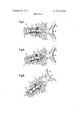
FIG. 7 is a top plan view showing another embodiment of the toe iron according to the invention in its normal position.
FIG. 8 is a sectional view showing the toe iron and taken on line VIII-VIII in FIG. 7.
FIG. 9 shows the toe iron of FIG. 7 in the instantaneous position at the end of the elastic range.
FIG. 10 shows the toe iron of FIG. 7 having completed its outward pivotal movement.
The toe iron shown in FIGS. l-3 comprises a base plate 1, which is adapted to be secured to a ski, e.g., by means of screws, and for this reason is provided with screw holes 2. The base plate 1 carries a vertical carrying pin 3, which on that half which faces the rear end of the ski is provided with a flat surface 4, which extends vertically and transversely to the longitudinal direction of the toe iron. A pivoted member 5 is mounted on the carrying pin 3 and for this purpose has a vertical aperture 6 in the form of a slot which has a width that is equal to the diameter of the carrying pin. Part of the surface which defines the aperture 6 consists also of a flat vertical surface 7 and constitutes a mating surface for cooperation with the flat 4, which is engaged by the pivoted member 5 when it is in its normal position. The pivoted member 5 also comprises a horizontal longitudinal bore 8, which is provided at its outer end with intemal screw threads 9. A piston 10 is guided in the bore 8 and is urged against the carrying pin 3 by one end of a helical compression spring 11. The other end of the spring bears on a screw plug 12, which is threaded into the threads 9. The spring is guided by a piston rod 13 and the latter is slidably guided in an internal bore 14 of the screw plug 12. By means of two pins 15, two soleholders 16 are pivoted to the pivoted member in a manner which is not described in detail because it is known per se. The soleholders 16 can be adjusted in height by the turning of a screw 17.
The surface 7 is formed with a recess 18 in such a manner that two vertical edge lands 19 formed by the surface 7 are left on both sides of the recess 18. The contour of the recess 18 comprises two arcuate portions, which have a slightly smaller radius than the carrying pin 3 and which are spaced apart by a nose 20. The purpose of this recess 18 will be described more in detail hereinafter.
When one of the soleholders 16 is acted upon by a force which is transverse to the longitudinal direction of the ski and, e.g., upwardly directed in FIGS. 1-3, and this force overcomes the spring force of the helical compression spring, the surface 7 of the pivoted member 5 will turn on the leading edge of the flat 4 so that the pivoted member is shifted to the rear, to the right in the drawing. The piston 10 cannot follow said longitudinal movement because it engages the carrying pin 3, which is rigid with the base plate. As a result, the spring 1 1 is stressed.
If the acting force is smaller than the force required for a release or acts only as a shock, the spring 11 will relax and return the toe iron to its normal position when the force decreases. As has been explained hereinbefore, the toe iron and skiing boot can be returned because the point of contact between the toe iron and the skiing boot describes, during the outward pivotal movement of the pivoted member, an arc of a circle which is tangent to or intersects the arc of a circle described by the toe portion of the skiing boot as the latter turns about the heel. As a result, the skiing boot cannot move forwardly during an outward pivotal movement, and only frictional forces, particularly between the ski and the sole of the skiing boot, must be overcome by the helical compression spring 11 in returning the toe iron.
When one of the soleholders 16 is acted upon by a force which exceeds the preset force required for a release and which does not act only as a shock, the pivoted member will turn on the carrying pin 3 as described hereinbefore until the position at the end of the elastic range has been reached. This position is shown in FIG. 2. As the pivotal movement is continued, the fulcrum on the carrying pin 3 enters the recess 18, which is defined by arcs which have a slightly smaller radius than the carrying pin. As a result, the stress of the helical compression spring 1 1 will be increased only slightly until the skiing boot is ultimately released so that there is hardly an increase of the force required for a continued pivotal movement. This force increases only to such an extent that the frictional forces can be overcome which oppose an automatic return of the toe iron to its central position when the boot has been released. To ensure that the outward pivotal movement of the pivoted member 5 will not exceed a certain angle, which limits the range in which the spring force acts in such a direction that an automatic return is ensured, the outward pivotal movement of the pivoted member is limited by the stop 20, as is shown in FIG. 3. In this position, that end of the aperture 6 of the pivoted member which is remote from the soleholders engages the carrying pin 3. The force required for a release of the toe iron is determined by the initial stress of the helical compression spring 11 and this initial stress is adjustable by means of the screw 12.
FIGS. 4-6 show a second embodiment of the toe iron according to the invention. Like parts are provided with the same reference numbers as in the first embodiment. The base plate 1 has screw holes 2 for the fixation of the base plate to the ski. A carrying pin 30 extends at right angles to the base plate 1 and is formed with four vertical flats 31, 32. The two flats 31 converge to the rear end of the ski and the two flats 32 converge to the tip of the ski. The vertices of these flats extend in the central vertical longitudinal plane of the toe iron. A pivoted member 33 is mounted on the carrying pin 30. A soleholder 34 is pivoted by a pin 35 to the pivoted member 33, which has a vertical aperture 36, which is hexagonal in cross-section and has a longest diagonal that is longer than the diagonal of the carrying pin 30 and extends in the longitudinal axis of the toe iron when the same is in normal position. In its normal position, shown in FIG. 4, those surfaces which define the aperture 36 that converges toward the soleholder 34 positively engage the carrying pin 30. As in the first embodiment, the pivoted member 33 has also a horizontal bore 8, which is closed on the outside by a screw plug 12 and in which a piston 37 is guided. In the normal position of the toe iron, this piston 37 also positively engages the carrying pin 30 and for this reason has a correspondingly shaped recess. A helical compression spring 11 is mounted on a piston rod 38 and at one end bears on the screw plug 12 whereas the other end of the spring bears on the piston 37 to urge it against the carrying pin 30. The force required for a release will depend on the initial stress of the spring. This initial stress can be changed by a turning of the screw plug 12 in the pivoted member 33.
This toe iron has basically the same function as the first embodiment. When the soleholder 34 is acted upon by a force which is transverse to the longitudinal direction of the ski, e.g., upwardly directed in FIGS. 4-6, and this force overcomes the spring force of the helical compression spring 11, the pivoted member will disengage its centering mounting means and will turn on the carrying pin 30. In this phase, the pivoted member 33 and the soleholder 34 are not only rotated but also shifted to the rear, to the right in FIGS. 46, so that the soleholder 34 follows the movement of the skiing boot and prevents a forward movement of the boot during the outward pivotal movement. Owing to the special mounting of the piston 37 on the carrying pin 30, the helical compression spring 11 is stressed not only by the rearward movement of the pivoted member 33 but also by the forward displacement of the piston 37 because the same turns on the carrying pin 20. As a result, a larger resistance to a release can be presented in a toe iron in which the pivoted member 33 must perform an outward pivotal movement through the same angle as in the first embodiment for a release and in which the same spring having the same initial stress is used as in said first embodiment. To limit the angle of the outward pivotal movement within a range in which an automatic return of the toe iron is enabled, the second embodiment is provided with stops for the piston 37. These stops are formed by the pins 39 of two screws 39, which are laterally and radially threaded into the pivoted member 33. As in shown in FIG. 6, the pins 39 extend into the bore 8 and limit the rearward movement of the piston 37 and the pivotal movement of the pivoted member 33.
In the embodiment of the invention shown in FIGS. 7-10, the detent and return spring is indirectly stressed by the displacement of the pivoted member in a direction which is radial relative to the carrying pin. As in the preceding embodiments, a base plate 40 is adapted to be secured to a ski by means of screws and for this purpose is provided with two screw holes 41. The base plate 40 carries also a vertical carrying pin 42, which has two flats 43, which converge toward the central vertical longitudinal plane and which have adjacent to the soleholder a vertex disposed in said longitudinal plane. A pivoted member 44 is formed with an aperture 45, which in the longitudinal direction of the pivoted member exceeds the diameter of the carrying pin 42 and which has also two converging vertical flats 46 (see particularly FIGS. 9 and 10), which constitute mating surfaces for engaging the carrying pin 42. The carrying pin 42 is provided at its top end with a collar 47, which covers the aperture 45 and prevents a lifting of the pivoted member 44 regardless of the position thereof. Such collar may also be provided in the embodiments described before to hold the pivoted member on the carrying pin. Two soleholders 49 are mounted by two pivots 48 on the pivoted member 44 and just as in the first embodiment can be adjusted in height by a screw 50. At that end which is remote from the soleholders 49, the pivoted member has a stepped vertical bore 51 (see particularly FIG. 8), which receives part of a detent and return device. A sleeve 53 is provided with a flange 52 and rotatably and axially slidably guided in the bore 51 and is biased by a helical compression spring 54 urging the flange 52 upwardly against an abutment 56, which is secured to the pivoted member 44 by means of a screw 55. The other end of the spring 54 bears on a ball 57 (see FIG. 8), which is axially displaceably guided in the lower portion of the stepped bore 51 and which bears on an upturned lug 58 of the base plate 40. The top edge of the lug 58 constitutes a locking and guiding track, which extends upwardly symmetrically to the central longitudinal axis of the toe iron and toward the rear end of the ski in accordance with the path described by the pivoted member 44 and the ball 57 during an outward pivotal movement. To ensure a satisfactory centering of the toe iron in its normal position, shown in FIGS. 7 and 8, the guiding track has in the middle a notch 59 (see FIG. 8), which receives the ball in the normal position. In known manner, the abutment 56 and the flange 52 of the sleeve 53 are stepped so that the initial stress of the spring and the force required for a release can .be adjusted by an axial displacement and subsequentrotation of the sleeve 53.
When the pivoted member is acted upon by a force which is is transverse to the longitudinal direction of the ski and, e.g., upwardly directed in the drawing, and which overcomes the initial stress of the helical compression spring 54, the pivoted member 44 turns on the carrying pin 42 as in the embodiments described hereinbefore and in addition to its pivotal movement is shifted to the rear in accordance with the teaching of the invention. During this phase, the detent ball 57 rolls on the guiding track 58 and owing to the configuration of said track the ball is raised so that the helical compression spring 54 is stressed (see FIGS. 9 and 10).
When the acting force decreases, the helical compression spring 54 forces the detent ball downwardly along the guiding track 58 so that the pivoted member is returned to its normal position.
When the pivoted member has performed a pivotal movement to a predetermined position, which is shown in FIG. 9 and indicates that the force required for a release has been reached, the ball will roll on a less steep portion of the guiding track 58 so that a further pivotal movement of the pivoted member until the release of the skiing boot (see FIG. 10), will result in an only small increase of the stress of the helical compres sion spring. This increase is merely sufficient to enable subsequently an automatic return of the toe iron to its normal position.
What is claimed is:
l. A toe iron for safety ski bindings, which toe iron comprises a pivoted member, a base plate, a vertical carrying pin rigid with said base plate, at least one soleholder carried by said pivoted member, and at least one spring in cooperating relationship with said pivoted member, the pivoted member being movable from its normal position against the force of said spring, said carrying pin having at least one vertical surface formed on a half of the carrying pin adjacent to the soleholder, said pivoted member having a vertical bore forming a bearing surface, a portion of said bearing surface comprising a mating surface, said mating surface engaging said vertical surface of said carrying pin when the pivoted member is in its normal position, said bearing surface being free from engagement with the half of the carrying pin which faces away from the soleholder when the pivoted member is in its normal position, and the radius of curvature of said mating surface being less than the radius of curvature of said vertical surface of said carrying pin such that said pivoted member and said soleholder are moved rearward during the outward pivotal movement of said pivoted member and such that said soleholder prevents the forward movement of the ski boot.
2. A toe iron according to claim 1, wherein said at least one vertical siirface is flat and extends tranversely to the longitudinal direction of the toe iron.
3. A toe iron according to claim 1, wherein said at least one vertical surface comprises two flat vertical surfaces which converge toward the soleholder and which define a vertex disposed on a central vertical longitudinal plane of the toe iron.
4. A toe iron according to claim 1 wherein said mating surface of said pivoted member has a recess which is defined by vertical edge lands.
5. A toe iron according to claim 1 wherein said pivoted member defines a horizontal recess, said spring being a helical compression spring mounted in said horizontal recess with one end of the spring bearing on the pivoted member, a piston in cooperating relationship with the spring, a second end of the spring acting by means of said piston on the carrying pin, that half of the carrying pin which is remote from the soleholder being symmetrical relative to the other half, and the piston defining a mating surface which engages the carrying pin when the pivoted member is in its normal position.
6. A toe iron according to claim 1 wherein said pivoted member has a second vertical bore and wherein said toe iron includes a locking and guiding track provided in said baseplate and a detent and returning device including a detent member and said at least one spring which consists of a helical compression spring mounted in said second vertical bore of said pivoted member and with its upper end bearing on said pivoted member and its lower end acting on said detent member to urge said detent member against said locking and guiding track, said locking and guiding track extending upwardly symmetrically to the central longitudinal axis of said toe iron and extending toward the rear end of the ski along the path followed by said pivoted member during its outward pivotal movement.
7. A toe iron according to claim 1 wherein said at least one soleholder is mounted on said pivoted member so that /it is capable of making a limited vertical pivotal movement about a vertical axis.
8. A toe iron according to claim 1 wherein said at least one soleholder is nonrotatably mounted on said pivoted member.