US3698764A - Chaise lounge - Google Patents
Chaise lounge Download PDFInfo
- Publication number
- US3698764A US3698764A US116184A US3698764DA US3698764A US 3698764 A US3698764 A US 3698764A US 116184 A US116184 A US 116184A US 3698764D A US3698764D A US 3698764DA US 3698764 A US3698764 A US 3698764A
- Authority
- US
- United States
- Prior art keywords
- frame
- notch
- backrest
- latch
- swingably
- Prior art date
- Legal status (The legal status is an assumption and is not a legal conclusion. Google has not performed a legal analysis and makes no representation as to the accuracy of the status listed.)
- Expired - Lifetime
Links
Images


Classifications
-
- A—HUMAN NECESSITIES
- A47—FURNITURE; DOMESTIC ARTICLES OR APPLIANCES; COFFEE MILLS; SPICE MILLS; SUCTION CLEANERS IN GENERAL
- A47C—CHAIRS; SOFAS; BEDS
- A47C17/00—Sofas; Couches; Beds
- A47C17/04—Seating furniture, e.g. sofas, couches, settees, or the like, with movable parts changeable to beds; Chair beds
- A47C17/045—Seating furniture having loose or by fabric hinge connected cushions changeable to beds
-
- A—HUMAN NECESSITIES
- A47—FURNITURE; DOMESTIC ARTICLES OR APPLIANCES; COFFEE MILLS; SPICE MILLS; SUCTION CLEANERS IN GENERAL
- A47C—CHAIRS; SOFAS; BEDS
- A47C1/00—Chairs adapted for special purposes
- A47C1/02—Reclining or easy chairs
- A47C1/022—Reclining or easy chairs having independently-adjustable supporting parts
- A47C1/024—Reclining or easy chairs having independently-adjustable supporting parts the parts, being the back-rest, or the back-rest and seat unit, having adjustable and lockable inclination
- A47C1/026—Reclining or easy chairs having independently-adjustable supporting parts the parts, being the back-rest, or the back-rest and seat unit, having adjustable and lockable inclination by means of peg-and-notch or pawl-and-ratchet mechanism
-
- A—HUMAN NECESSITIES
- A47—FURNITURE; DOMESTIC ARTICLES OR APPLIANCES; COFFEE MILLS; SPICE MILLS; SUCTION CLEANERS IN GENERAL
- A47C—CHAIRS; SOFAS; BEDS
- A47C1/00—Chairs adapted for special purposes
- A47C1/02—Reclining or easy chairs
- A47C1/031—Reclining or easy chairs having coupled concurrently adjustable supporting parts
- A47C1/036—Reclining or easy chairs having coupled concurrently adjustable supporting parts the parts including a head-rest
-
- A—HUMAN NECESSITIES
- A47—FURNITURE; DOMESTIC ARTICLES OR APPLIANCES; COFFEE MILLS; SPICE MILLS; SUCTION CLEANERS IN GENERAL
- A47C—CHAIRS; SOFAS; BEDS
- A47C1/00—Chairs adapted for special purposes
- A47C1/14—Beach chairs ; Chairs for outdoor use, e.g. chairs for relaxation or sun-tanning
- A47C1/143—Chaise lounges
-
- A—HUMAN NECESSITIES
- A47—FURNITURE; DOMESTIC ARTICLES OR APPLIANCES; COFFEE MILLS; SPICE MILLS; SUCTION CLEANERS IN GENERAL
- A47C—CHAIRS; SOFAS; BEDS
- A47C31/00—Details or accessories for chairs, beds, or the like, not provided for in other groups of this subclass, e.g. upholstery fasteners, mattress protectors, stretching devices for mattress nets
- A47C31/10—Loose or removable furniture covers
- A47C31/11—Loose or removable furniture covers for chairs
Definitions
- a chaise lounge having a base frame and a body 4 Field of Search 372, 441, 219, mounted thereon with an extension of said body form- 297/218,191,377,410,452;5/353-2 ing a backrest adjustable from a horizontal to an inclined position, and a flexible generally horizontal References cued mounted support carried between spaced cross mem- UNITED STATES PATENTS bers beneath said backrest with an adjustable braeket for maintaining said backrest In an elevated position, 3,310,343 3/1967 Schultz ..297/445 and a removable covering f i body, Said body 714,177 11/1902 Harris ..297/356 being id d ith d v tailed grooving along the- 663,582 12/1900 Robbin ..297/356 s and said covering being retained therein by a 17
- the present invention is a chaise longue having a portable base with a support frame and an adjustable backrest mounted thereon.
- One or more cushions are carried by the frame and a covering extends across such cushions and is removably connected to the frame.
- a caddy or support for small articles is mounted on the base below the headrest.
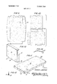
- FIG. 1 is a perspective illustrating one application of the invention.
- FIG. 2 is an exploded view of the chaise longue.
- FIG. 3 is a central longitudinal section.
- FIG. 4 is a transverse section on the line 4-4 of FIG. 2.
- FIG. 5 is an enlarged fragmentary detail section on the line of 5-5 of FIG. 3.
- FIG. 6 is an enlarged fragmentary detail viewed from the underside of the longue on the line 6-6 of FIG. 4.
- FIG. 7 is an enlarged fragmentary transverse detail section on the line 7-7 of FIG. 4.
- FIG. 8 is a'fragmentary longitudinal section through a portion of the supporting bracket and revealing the latch or pawl.
- FIGS. 9 and 10 are layouts of the coverings for the cushions of the chaise longue.
- FIGS. 11 and 12 are the coverings of FIGS. 9-and l0 shaped and sewn ready for application.
- FIG. 13 is a section on the line 13-13 of FIG. 11 revealing the hem and resilient retention member.
- FIG. 14 is a view of the retention member itself.
- FIG. 15 is an enlarged fragmentary section similar to FIG. 7 of a modified form of the invention.
- the frame 16 includes a pair of side members l8 and end members 19 and 20.
- a cushion support or platform 21, such as a pegboard having multiple small openings 21' is fastened to the side members 18 and end members 19 and 20.
- the side members 18 and the end member 19 are provided with grooves 18 and 19 in which the edges of the platform 21 are received.
- the other end of the platform abuts the end member 20, and a pair of reinforcing blocks 23 and 24 overlie the joint and are fastened in place by adhesive or other fastening means, not shown.
- the backrest is substantially square with a cushion support or platform 25, such as a pegboard (FIG. 3) supported on side members 26 and end members 27 and 28.
- the backrest is connected by a piano hinge 29 with the end member 20 permitting the backrest to be disposed in a generally horizontal position or in multiple elevated positions.
- the hinge 29, as well as the cushions or padding 30 and 31 on the platforms 21 and 25 of the frame 16 and backrest 17, are provided with a covering 32.
- Such covering may be of woven or nonwoven material which is either waterproof or non-waterproof as desired.
- the end member 19 is provided with dovetail grooves 33 and 34 in its upper and lower surfaces
- the end member 20 is provided with a groove 34' in its bottom surface
- the side members 18 are provided with upper and lower dovetail grooves 35 and 36.
- the backrest is provided with corresponding grooves in its sides 26 and its end 28, while on its end 27 there are spaced parallel grooves on the vertical surface facing the bottom portion of the chaise longue. In these several grooves the covering 32 is inserted and retained.
- the covering is provided with a hem 37 along its margin in which is received a yieldable insert 38 of rubber slightly larger in diameter than the width of the grooves which will retain the covering in place when the yieldable insert is forced into the dovetail grooving around the margin of the respective areas.
- the covering for the frame and frame cushion of the chaise longue may be formed from a single sheet with a tuck at each corner so that the covering will fit.
- the covering for the backrest is formed from a single sheet large enough to cover the front and three sides of the backrest, with a separate sheet at the back so that when the sides are sewn together it will provide in effect an envelope or afive-sided bag with an open end.
- the covering preferably is prefabricated so that it may be readily applied and, if desired, removed and replaced by the user without requiring the services of an upholsterer. When thus installed the covering will be smooth and unwrinkled and retain the cushions 30 and 31 in place.
- the backrest may also carry a headrest 39 supported'by a pair of brackets 40 slidable in fittings 41 fastened to the end member 28 of the backrest and clamped in place by knurled screws 42.
- a pair of spaced, generally parallel arms 43 are connected to the ventilating support or pegboard 25 lengthwise of the backrest 17 and extend through an opening 44 in the end members 27 (FIG. 6) of the backrest.
- a generally hollow housing 45 having side walls 46 and a bottom wall 47 is disposed below the platform 21 and is provided with a hook 48 at one end adapted to be received in an opening in an attaching member 49 fixed to the end wall 19 of the frame 16 so that it may have a limited swinging movement.
- An extensible member or tongue 50 is slidably mounted for lengthwise movement within thehousing 45.
- One end of the tongue 50 is swingably connected to the parallel arms 43 in any desired manner, such as a hook 51 which extends about and pivots upon one of a pairof dowels 52 at the end of the arms 43.
- the upper portion of the tongue 50 is provided with a cam surface 53 having indentations or pockets 54 and 55 at opposite ends and one or more intermediate notches 56.
- the side walls 46 of the housing are connected by a transverse pivot pin 57 on which a latch or pawl 58 is swingably mounted. Such pawl normally is urged into contact with the cam surface 53 by an elastic or spring member 59.
- the pawl 58 When the backrest 17 is in collapsed positions as illustrated in FIG. 3, the pawl 58 will be disposed in a generally vertical position within the pocket 54.
- the arms 43 When the backrest is raised about the hinge 29, the arms 43 will move the tongue 50 outwardly of the housing 45 so that the cam surface 53 will engage the pawl 58 and swing the same about the pin 57.
- the intermediate notches 56 Continued outward movement of the tongue 50 will cause the intermediate notches 56 to pass under the pawl 58 and permit the end of the pawl to engage one notch at a time and secure the backrest in adjusted position.
- the tongue 50 has notches of a depth less than the depth of the latch or pawl, which will be engaged by the latch or pawl and prevent the two members from collapsing and maintain them in their expanded position until the tongue is fully extended and permits the latch or pawl to drop into the deeper notch and revolve past dead center, thus allowing the members 45 and 50 to retelescope.
- the backrest can be disposed in horizontal or in multiple elevated positions in accordance with the movement relative to notches in which the latch or pawl can be received.
- the extensible member is provided with a shoulder 60 adapted to engage a cross pin or stop 61 carried by he side walls 46 and which extends across the path of movement of the shoulder and limits the longitudinal separation of the members 45 and 50.
- the padding is constructedof resilient material such as sponge rubber, foam plastic or other resilient cellular material.
- the platforms 2] and 25 may be constructed of solid non-perforated material such as plywood or the like instead of the pegboard as previously described, and the covering 32 may be of any flexible waterproof material such as sheet rubbe or thermoplastic material in sheet form.
- the frame 16 and covering 32 should be substantially airtight; however, in order for the cushions or padding 30 nd 31 to expand and contract with the weight of a person, air must be permitted to enter and i leave the cushions.
- each of the platforms 21 and 25 includes at least two openings 64 and 65 which receive inlet and outlet valves 66 and 67, respectively.
- the inlet valve 66 preferably includes a generally cylindrical housing 68 with a perforated plate 69 at one end and a flapper type valve 70 at the opposite end.
- the flapper valve 70 is adapted to open inwardly to permit air to enter the housing 68 and pass through the perforated plate 69 into the area of the padding or cushions.
- a desiccant 71 such as phosphorus pentoxide P 0 aluminum oxide Al 0 calcium oxide Ca 0, or the like, is located between the perforated plate 69 and the flapper valve 70.
- the desiccant may be in either crystalline or powder form.
- the inlet valve may be large enough to supply aid to the entire cushion, or if desired a plurality of smaller inlet valves could be spaced about the platforms 21 and 25. In any event, provision should be made for separating the inlet valve 66 so that the desiccant 71 can be replaced.
- the outlet valve 67 includes a cylindrical housing 72 having a perforated plate 73 at one end and a flapper type valve 74 at the opposite end.
- the flapper valve 74 is adapted to swing outwardly of the housing to permit air to be discharged from the cushion when a weight is applied thereon.
- a single relatively large outlet valve can be provided to accommodate the entire cushion, or a plurality of smaller outlet valves can be spaced throughout the platforms 21 and 25
- each of the cushions 30 and 31 could be independently enclosed in an airtight envelope with one or more inlet and outlet valves 66 and 67 mounted within the envelope material in which case the covering 32 could be of woven or other non-waterproof material and he platforms 21 and 25 could be perforated as previously described.
- An articulated supporting frame for a cushion comprising a first portion and a second portion connected together by hinge means, a cushion carried by said frame, said first frame portion normally supported in a generally horizontal position and said second frame portion being swingable from a horizontally supported coextensive position with said first portion to an inclined position, means for securing said second portion in at least one inclined position, said securing means including arm means fixed to said second portion and having one end extending outwardly to a position underlying said first portion when said first and second portions are coextensive, a first member swingably mounted on said first portion in a position remote from said hinge, a second member telescopically connected to said first member and having one end swingably connected to said arm means, said second member including a cam surface having a recess at each end and at least one notch intermediate the ends, latch means swingably carried by said first member with biasing means for causing said latch means to selectively engage said cam surface, and said latch means adapted to engage said notch when said second member is moved
- the structure of claim 1 including a base for supporting said frame.
- a chaise longue comprising a base, a first frame horizontally supported by said base, a second frame swingably connected to said first frame and providing a back rest, said second frame being movable from a horizontally supported position to at least one inclined position, means for securing said second frame in inclined position, said securing means including arm means mounted on said second frame and extending outwardly beneath a portion of said first frame in spaced relation to said swingable connection, a housing swingably mounted on said first frame, tongue means telescopically carried by said housing and having one end extending therefrom, said one end being swingably connected to said arm means, a portion of said tongue means including a cam surface having a recess at each end and at least one notch intermediate the ends thereof, latch means swingably mounted within said
Landscapes
- Health & Medical Sciences (AREA)
- General Health & Medical Sciences (AREA)
- Dentistry (AREA)
- Nursing (AREA)
- Chairs For Special Purposes, Such As Reclining Chairs (AREA)
Abstract
A chaise lounge having a base frame and a body mounted thereon with an extension of said body forming a backrest adjustable from a horizontal to an inclined position, and a flexible generally horizontal mounted support carried between spaced cross members beneath said backrest with an adjustable bracket for maintaining said backrest in an elevated position, and a removable covering for said body, said body being provided with dovetailed grooving along the same and said covering being retained therein by a resilient compressed insert.
Description
United States Patent [151 3,698,764 Geddings 1 Oct. 17, 1972 [541 cIIAIsE LOUNGE 3,205,005 9/1965 1 Brown ..2'97/410 x Inventor: Arthur J. di g w Reeve X 23223 Myrtle Bead" FOREIGN PATENTS OR APPLICATIONS Filed: Feb. 1971 444,184 l/1949 Italy ..297/372 [21] App1.No.: 116,184 Primary Examiner-Francis K. Zugel Attorney-A. Yates Dowell and A. Yates Dowell, Jr. [52] US. Cl. ..297/356, 297/377, ABSTRACT [51] lnt.Cl ..A47c 17/16 A chaise lounge having a base frame and a body 4 Field of Search 372, 441, 219, mounted thereon with an extension of said body form- 297/218,191,377,410,452;5/353-2 ing a backrest adjustable from a horizontal to an inclined position, and a flexible generally horizontal References cued mounted support carried between spaced cross mem- UNITED STATES PATENTS bers beneath said backrest with an adjustable braeket for maintaining said backrest In an elevated position, 3,310,343 3/1967 Schultz ..297/445 and a removable covering f i body, Said body 714,177 11/1902 Harris ..297/356 being id d ith d v tailed grooving along the- 663,582 12/1900 Robbin ..297/356 s and said covering being retained therein by a 175,211 3/1876 Unver zagt ..297/372 X resilient compressed insert 3,197,789 8/1965 Ashkouti ..5/353.2 X 3,298,743 1/1967 Albinson ..297/452 X 5 Claims, 15 Drawing Figures 1 F f I] /9 27A 2.; /9 Iv 34 BACKGROUND OF THE INVENTION 1. Field of the Invention The invention relates to furniture of the more or less leisure time type for promoting rest and relaxation, and relates especially to chaise longues.
2. Description of the Prior Art Various types of chaise longues have been provided all of which have been subject to criticism for various reasons, including unsuitability for either or both indoor and outdoor use, lacking interchangeability of coverings and a caddy or flexible horizontal support beneath an adjustable backrest so that inadvertent lowering of the backrest into contact with articles on the support would not cause damage to such articles due to yieldability. of the flexible support.
SUMMARY OF THE INVENTION AND OBJECTS The present invention is a chaise longue having a portable base with a support frame and an adjustable backrest mounted thereon. One or more cushions are carried by the frame and a covering extends across such cushions and is removably connected to the frame. A caddy or support for small articles is mounted on the base below the headrest.
It is an object of the invention to provide a chaise longue having a simple, inexpensive base frame with a body portion and an adjustable backrest hinged thereto, with the shorter backrest portion elevatable to multiple adjusted positions, with a flexible caddy or support for small objects beneath the same and with selective coverings and each removably held by dovetailing in which the fabric is inserted and held therein by a resilient compressed filler piece.
BRIEF DESCRIPTION OF THE DRAWINGS FIG. 1 is a perspective illustrating one application of the invention.
FIG. 2 is an exploded view of the chaise longue.
FIG. 3 is a central longitudinal section.
FIG. 4 is a transverse section on the line 4-4 of FIG. 2.
FIG. 5 is an enlarged fragmentary detail section on the line of 5-5 of FIG. 3.
FIG. 6 is an enlarged fragmentary detail viewed from the underside of the longue on the line 6-6 of FIG. 4.
FIG. 7 is an enlarged fragmentary transverse detail section on the line 7-7 of FIG. 4.
FIG. 8 is a'fragmentary longitudinal section through a portion of the supporting bracket and revealing the latch or pawl.
FIGS. 9 and 10 are layouts of the coverings for the cushions of the chaise longue.
FIGS. 11 and 12 are the coverings of FIGS. 9-and l0 shaped and sewn ready for application.
FIG. 13 is a section on the line 13-13 of FIG. 11 revealing the hem and resilient retention member.
FIG. 14 is a view of the retention member itself.
FIG. 15 is an enlarged fragmentary section similar to FIG. 7 of a modified form of the invention.
DESCRIPTION OF THE PREFERRED EMBODIMENTS rungs 12, 13 and 14 with a fabric 15 attached about and between the cross rungs 13 and 14 to provide a caddy, or support, for miscellaneous articles such as books, magazines, lotion or other articles. By using the fabric, a yieldable support is provided which will reduce breakage due to its yieldability when the backrest is lowered and which would not be the case if a solid support were provided.
On the base frame 10 is mounted a frame 16 and a backrest 17. The frame 16 includes a pair of side members l8 and end members 19 and 20. A cushion support or platform 21, such as a pegboard having multiple small openings 21' is fastened to the side members 18 and end members 19 and 20. The side members 18 and the end member 19 are provided with grooves 18 and 19 in which the edges of the platform 21 are received. The other end of the platform abuts the end member 20, and a pair of reinforcing blocks 23 and 24 overlie the joint and are fastened in place by adhesive or other fastening means, not shown.
The backrest is substantially square with a cushion support or platform 25, such as a pegboard (FIG. 3) supported on side members 26 and end members 27 and 28. The backrest is connected by a piano hinge 29 with the end member 20 permitting the backrest to be disposed in a generally horizontal position or in multiple elevated positions. Preferably the hinge 29, as well as the cushions or padding 30 and 31 on the platforms 21 and 25 of the frame 16 and backrest 17, are provided with a covering 32. Such covering may be of woven or nonwoven material which is either waterproof or non-waterproof as desired.
In order to fasten the covering 32 in place, the end member 19 is provided with dovetail grooves 33 and 34 in its upper and lower surfaces, the end member 20 is provided with a groove 34' in its bottom surface, and the side members 18 are provided with upper and lower dovetail grooves 35 and 36. In like manner, the backrest is provided with corresponding grooves in its sides 26 and its end 28, while on its end 27 there are spaced parallel grooves on the vertical surface facing the bottom portion of the chaise longue. In these several grooves the covering 32 is inserted and retained. The covering is provided with a hem 37 along its margin in which is received a yieldable insert 38 of rubber slightly larger in diameter than the width of the grooves which will retain the covering in place when the yieldable insert is forced into the dovetail grooving around the margin of the respective areas.
The covering for the frame and frame cushion of the chaise longue may be formed from a single sheet with a tuck at each corner so that the covering will fit. The covering for the backrest is formed from a single sheet large enough to cover the front and three sides of the backrest, with a separate sheet at the back so that when the sides are sewn together it will provide in effect an envelope or afive-sided bag with an open end. The
margin of the covering for the backrest is provided with a hem with a yieldable insert by means of which the covering may be fastened in place. The covering preferably is prefabricated so that it may be readily applied and, if desired, removed and replaced by the user without requiring the services of an upholsterer. When thus installed the covering will be smooth and unwrinkled and retain the cushions 30 and 31 in place.
For greater comfort the backrest may also carry a headrest 39 supported'by a pair of brackets 40 slidable in fittings 41 fastened to the end member 28 of the backrest and clamped in place by knurled screws 42.
In order to support the backrest with the headrest attached thereto in adjusted elevated position, a pair of spaced, generally parallel arms 43 are connected to the ventilating support or pegboard 25 lengthwise of the backrest 17 and extend through an opening 44 in the end members 27 (FIG. 6) of the backrest. A generally hollow housing 45 having side walls 46 and a bottom wall 47 is disposed below the platform 21 and is provided with a hook 48 at one end adapted to be received in an opening in an attaching member 49 fixed to the end wall 19 of the frame 16 so that it may have a limited swinging movement.
An extensible member or tongue 50 is slidably mounted for lengthwise movement within thehousing 45. One end of the tongue 50 is swingably connected to the parallel arms 43 in any desired manner, such as a hook 51 which extends about and pivots upon one of a pairof dowels 52 at the end of the arms 43. The upper portion of the tongue 50 is provided with a cam surface 53 having indentations or pockets 54 and 55 at opposite ends and one or more intermediate notches 56. In order to secure the housing 45 and the tongue 50in a fixed position of adjustment, the side walls 46 of the housing are connected by a transverse pivot pin 57 on which a latch or pawl 58 is swingably mounted. Such pawl normally is urged into contact with the cam surface 53 by an elastic or spring member 59. When the backrest 17 is in collapsed positions as illustrated in FIG. 3, the pawl 58 will be disposed in a generally vertical position within the pocket 54. When the backrest is raised about the hinge 29, the arms 43 will move the tongue 50 outwardly of the housing 45 so that the cam surface 53 will engage the pawl 58 and swing the same about the pin 57. Continued outward movement of the tongue 50 will cause the intermediate notches 56 to pass under the pawl 58 and permit the end of the pawl to engage one notch at a time and secure the backrest in adjusted position.
To lower the backrest, such backrest is raised until the pawl 58 enters the pocket 55 and assumes a vertical position, after which the backrest is lowered and the tongue 50 is moved into the housing 45. During the return movement of the tongue, the cam surface 53 will swing the pawl 58 in the opposite direction so that it will merely ride over the intermediate notches 56 until the backrest is in collapsed position again. In other words, the tongue 50 has notches of a depth less than the depth of the latch or pawl, which will be engaged by the latch or pawl and prevent the two members from collapsing and maintain them in their expanded position until the tongue is fully extended and permits the latch or pawl to drop into the deeper notch and revolve past dead center, thus allowing the members 45 and 50 to retelescope. Thus the backrest can be disposed in horizontal or in multiple elevated positions in accordance with the movement relative to notches in which the latch or pawl can be received. Preferably the extensible member is provided with a shoulder 60 adapted to engage a cross pin or stop 61 carried by he side walls 46 and which extends across the path of movement of the shoulder and limits the longitudinal separation of the members 45 and 50.
With reference to FIG. 15, when the chaise longue of the present invention is to be used in areas of high humidity, such as adjacent to swimming pools or large bodies of water, it is desirable to exclude the moisture from the padding or cushions and 31. As illustrated, the padding is constructedof resilient material such as sponge rubber, foam plastic or other resilient cellular material. In this modification the platforms 2] and 25 may be constructed of solid non-perforated material such as plywood or the like instead of the pegboard as previously described, and the covering 32 may be of any flexible waterproof material such as sheet rubbe or thermoplastic material in sheet form. The frame 16 and covering 32 should be substantially airtight; however, in order for the cushions or padding 30 nd 31 to expand and contract with the weight of a person, air must be permitted to enter and i leave the cushions. As illustrated, each of the platforms 21 and 25 includes at least two openings 64 and 65 which receive inlet and outlet valves 66 and 67, respectively. The inlet valve 66 preferably includes a generally cylindrical housing 68 with a perforated plate 69 at one end and a flapper type valve 70 at the opposite end. The flapper valve 70 is adapted to open inwardly to permit air to enter the housing 68 and pass through the perforated plate 69 into the area of the padding or cushions.
In order to absorb moisture passing through the inlet valve 66, a desiccant 71 such as phosphorus pentoxide P 0 aluminum oxide Al 0 calcium oxide Ca 0, or the like, is located between the perforated plate 69 and the flapper valve 70. The desiccant may be in either crystalline or powder form. r V
The inlet valve may be large enough to supply aid to the entire cushion, or if desired a plurality of smaller inlet valves could be spaced about the platforms 21 and 25. In any event, provision should be made for separating the inlet valve 66 so that the desiccant 71 can be replaced.
The outlet valve 67 includes a cylindrical housing 72 having a perforated plate 73 at one end and a flapper type valve 74 at the opposite end. The flapper valve 74 is adapted to swing outwardly of the housing to permit air to be discharged from the cushion when a weight is applied thereon. A single relatively large outlet valve can be provided to accommodate the entire cushion, or a plurality of smaller outlet valves can be spaced throughout the platforms 21 and 25 As an alternative, each of the cushions 30 and 31 could be independently enclosed in an airtight envelope with one or more inlet and outlet valves 66 and 67 mounted within the envelope material in which case the covering 32 could be of woven or other non-waterproof material and he platforms 21 and 25 could be perforated as previously described.
It will be apparent from the foregoing that a simple, inexpensive chaise longue is provided which may be readily manufactured from readily available materials and if desired the coverings may be readily changed or different color schemes or motifs.
Iclaim:
1. An articulated supporting frame for a cushion, said frame comprising a first portion and a second portion connected together by hinge means, a cushion carried by said frame, said first frame portion normally supported in a generally horizontal position and said second frame portion being swingable from a horizontally supported coextensive position with said first portion to an inclined position, means for securing said second portion in at least one inclined position, said securing means including arm means fixed to said second portion and having one end extending outwardly to a position underlying said first portion when said first and second portions are coextensive, a first member swingably mounted on said first portion in a position remote from said hinge, a second member telescopically connected to said first member and having one end swingably connected to said arm means, said second member including a cam surface having a recess at each end and at least one notch intermediate the ends, latch means swingably carried by said first member with biasing means for causing said latch means to selectively engage said cam surface, and said latch means adapted to engage said notch when said second member is moved in one direction and to bypass said notch when said second member is moved in the opposite direction, whereby said second frame portion can be swung about said hinge means and cause said second member to be extended from said first member carried by said first frame portion and said latch means selectively engages said notch to support said second frame portion in adjusted position.
2. The structure of claim 1 including stop means for limiting the movement of said second member relative to said first member.
3. The structure of claim 1 including a base for supporting said frame.
4. The structure of claim 1 including dovetail grooving about the periphery of said frame, sheet material covering said cushion and having portions extending into said grooving, and resilient retention means compressed within said dovetail grooving to maintain said portions of sheet material in said grooving but permitting removal and replacement thereof.
5. A chaise longue comprising a base, a first frame horizontally supported by said base, a second frame swingably connected to said first frame and providing a back rest, said second frame being movable from a horizontally supported position to at least one inclined position, means for securing said second frame in inclined position, said securing means including arm means mounted on said second frame and extending outwardly beneath a portion of said first frame in spaced relation to said swingable connection, a housing swingably mounted on said first frame, tongue means telescopically carried by said housing and having one end extending therefrom, said one end being swingably connected to said arm means, a portion of said tongue means including a cam surface having a recess at each end and at least one notch intermediate the ends thereof, latch means swingably mounted within said
Claims (5)
1. An articulated supporting frame for a cushion, said frame comprising a first portion and a second portion connected together by hinge means, a cushion carried by said frame, said first frame portion normally supported in a generally horizontal position and said second frame portion being swingable from a horizontally supported coextensive position with said first portion to an inclined position, means for securing said second portion in at least one inclined position, said securing means including arm means fixed to said second portion and having one end extending outwardly to a position underlying said first portion when said first and second portions are coextensive, a first member swingably mounted on said first portion in a position remote from said hinge, a second member telescopically connected to said first member and having one end swingably connected to said arm means, said second member including a cam surface having a recess at each end and at least one notch intermediate the ends, latch means swingably carried by said first member with biasing means for causing said latch means to selectively engage said cam surface, and said latch means adapted to engage said notch when said second member is moved in one direction and to bypass said notch when said second member is moved in the opposite direction, whereby said second frame portion can be swung about said hinge means and cause said second member to be extended from said first member carried by said first frame portion and said latch means selectively engages said notch to support said second frame portion in adjusted position.
2. The structure of cLaim 1 including stop means for limiting the movement of said second member relative to said first member.
3. The structure of claim 1 including a base for supporting said frame.
4. The structure of claim 1 including dovetail grooving about the periphery of said frame, sheet material covering said cushion and having portions extending into said grooving, and resilient retention means compressed within said dovetail grooving to maintain said portions of sheet material in said grooving but permitting removal and replacement thereof.
5. A chaise longue comprising a base, a first frame horizontally supported by said base, a second frame swingably connected to said first frame and providing a back rest, said second frame being movable from a horizontally supported position to at least one inclined position, means for securing said second frame in inclined position, said securing means including arm means mounted on said second frame and extending outwardly beneath a portion of said first frame in spaced relation to said swingable connection, a housing swingably mounted on said first frame, tongue means telescopically carried by said housing and having one end extending therefrom, said one end being swingably connected to said arm means, a portion of said tongue means including a cam surface having a recess at each end and at least one notch intermediate the ends thereof, latch means swingably mounted within said housing, elastic means for causing said latch means to selectively engage said cam surface when said surface is moved in one direction, and said latch means adapted to engage said notch when the tongue means is moved in said one direction, whereby said second frame can be swung about the connection to said first frame and said arm means causes said tongue means to be extended from the housing carried by said first frame, and said latch means engages said notch to support said second frame in adjusted position.
Applications Claiming Priority (1)
| Application Number | Priority Date | Filing Date | Title |
|---|---|---|---|
| US11618471A | 1971-02-17 | 1971-02-17 |
Publications (1)
| Publication Number | Publication Date |
|---|---|
| US3698764A true US3698764A (en) | 1972-10-17 |
Family
ID=22365770
Family Applications (1)
| Application Number | Title | Priority Date | Filing Date |
|---|---|---|---|
| US116184A Expired - Lifetime US3698764A (en) | 1971-02-17 | 1971-02-17 | Chaise lounge |
Country Status (1)
| Country | Link |
|---|---|
| US (1) | US3698764A (en) |
Cited By (13)
| Publication number | Priority date | Publication date | Assignee | Title |
|---|---|---|---|---|
| US4421035A (en) * | 1980-04-15 | 1983-12-20 | Triumph-Adler A.G. Fur Buro-Und Informationstechnik | Apparatus for locking a keyboard at selected inclinations to a horizontal reference |
| US4824174A (en) * | 1988-05-02 | 1989-04-25 | Dunn Richard A Sr | Seating device |
| US5397168A (en) * | 1993-09-02 | 1995-03-14 | Bemis Manufacturing Company | Chair with adjustable backrest |
| US20060267393A1 (en) * | 2005-05-04 | 2006-11-30 | Benites Gabriel M | Utility bench |
| US9089224B1 (en) * | 2014-06-21 | 2015-07-28 | L&P Property Management Company | Replaceable basecover mechanism |
| US9414693B2 (en) | 2014-06-21 | 2016-08-16 | L & P Property Management Company | Replaceable basecover mechanism |
| US9420896B2 (en) | 2014-06-21 | 2016-08-23 | L&P Property Management Company | Replaceable basecover mechanism |
| US10058179B2 (en) * | 2015-11-30 | 2018-08-28 | Era Nouveau, LLC | Adjustable fully upholstered chaise lounger |
| EP3369345A1 (en) * | 2017-03-01 | 2018-09-05 | Doc AG | Reclining surface with tilt adjusters |
| USD880882S1 (en) * | 2017-12-20 | 2020-04-14 | Rh Us, Llc | Chaise |
| USD891801S1 (en) * | 2017-12-21 | 2020-08-04 | Rh Us, Llc | Chaise |
| USD925242S1 (en) * | 2019-05-15 | 2021-07-20 | Blu Dot Design & Manufacturing, Inc. | Lounger |
| USD939229S1 (en) * | 2019-08-29 | 2021-12-28 | Keter Plastic Ltd. | Sun lounger |
-
1971
- 1971-02-17 US US116184A patent/US3698764A/en not_active Expired - Lifetime
Cited By (17)
| Publication number | Priority date | Publication date | Assignee | Title |
|---|---|---|---|---|
| US4421035A (en) * | 1980-04-15 | 1983-12-20 | Triumph-Adler A.G. Fur Buro-Und Informationstechnik | Apparatus for locking a keyboard at selected inclinations to a horizontal reference |
| US4824174A (en) * | 1988-05-02 | 1989-04-25 | Dunn Richard A Sr | Seating device |
| US5397168A (en) * | 1993-09-02 | 1995-03-14 | Bemis Manufacturing Company | Chair with adjustable backrest |
| US20060267393A1 (en) * | 2005-05-04 | 2006-11-30 | Benites Gabriel M | Utility bench |
| US9089224B1 (en) * | 2014-06-21 | 2015-07-28 | L&P Property Management Company | Replaceable basecover mechanism |
| US9414693B2 (en) | 2014-06-21 | 2016-08-16 | L & P Property Management Company | Replaceable basecover mechanism |
| US9420896B2 (en) | 2014-06-21 | 2016-08-23 | L&P Property Management Company | Replaceable basecover mechanism |
| US11134779B2 (en) * | 2015-11-30 | 2021-10-05 | Era Nouveau, LLC | Adjustable fully upholstered chaise lounger |
| US10058179B2 (en) * | 2015-11-30 | 2018-08-28 | Era Nouveau, LLC | Adjustable fully upholstered chaise lounger |
| US11849848B2 (en) * | 2015-11-30 | 2023-12-26 | Era Nouveau, LLC | Adjustable fully upholstered chaise lounger |
| US20190059591A1 (en) * | 2015-11-30 | 2019-02-28 | Era Nouveau, LLC | Adjustable fully upholstered chaise lounger |
| EP3369345A1 (en) * | 2017-03-01 | 2018-09-05 | Doc AG | Reclining surface with tilt adjusters |
| CN108606540A (en) * | 2017-03-01 | 2018-10-02 | 道格有限公司 | The face that lies down with inclination angle adjustor |
| USD880882S1 (en) * | 2017-12-20 | 2020-04-14 | Rh Us, Llc | Chaise |
| USD891801S1 (en) * | 2017-12-21 | 2020-08-04 | Rh Us, Llc | Chaise |
| USD925242S1 (en) * | 2019-05-15 | 2021-07-20 | Blu Dot Design & Manufacturing, Inc. | Lounger |
| USD939229S1 (en) * | 2019-08-29 | 2021-12-28 | Keter Plastic Ltd. | Sun lounger |
Similar Documents
| Publication | Publication Date | Title |
|---|---|---|
| US4484781A (en) | Flotation chair | |
| US3698764A (en) | Chaise lounge | |
| US3761131A (en) | Article of furniture and method of manufacturing same | |
| US3792501A (en) | Air chairs and convertible sofas | |
| US4654907A (en) | Folding recreation chair-pad | |
| US4442556A (en) | Sofa bed with inflatable mattress | |
| US3743351A (en) | Laterally expandable couch | |
| US3944281A (en) | Modular members for composing pieces of furniture, as padded chairs, easy-chairs, divans and divans convertible in beds | |
| US6155647A (en) | Upholstered seat systems for leisure chairs | |
| US3070402A (en) | Upholstered seating and furniture | |
| US2864438A (en) | Upholstered furniture | |
| GB2042333A (en) | Ottoman convertible to a bed | |
| US8939505B1 (en) | Adjustable portable booster cushion for adults | |
| US3643997A (en) | Seating unit and web therefor | |
| US3685063A (en) | Furniture | |
| US20160278533A1 (en) | Sofa-bed Air Mattress Combination | |
| US4232411A (en) | Combination bed and lounge assembly | |
| US3560049A (en) | Sofa with integral cushion | |
| US20140130252A1 (en) | Pnuematic bed system with table | |
| US5865504A (en) | Reclining backrest system for a person in a wheelchair | |
| US4326309A (en) | Bedding device | |
| US3916460A (en) | Sofa bed and mechanism therefor | |
| US2878860A (en) | Seat construction | |
| US10813482B2 (en) | Portable mattress seating apparatus | |
| US4343509A (en) | Piece of seating furniture |