US3694271A - Method of producing articles of composite material,and resulting products - Google Patents
Method of producing articles of composite material,and resulting products Download PDFInfo
- Publication number
- US3694271A US3694271A US152156A US3694271DA US3694271A US 3694271 A US3694271 A US 3694271A US 152156 A US152156 A US 152156A US 3694271D A US3694271D A US 3694271DA US 3694271 A US3694271 A US 3694271A
- Authority
- US
- United States
- Prior art keywords
- steel
- ferritic
- austenitic
- composite material
- temperature
- Prior art date
- Legal status (The legal status is an assumption and is not a legal conclusion. Google has not performed a legal analysis and makes no representation as to the accuracy of the status listed.)
- Expired - Lifetime
Links
Images
Classifications
-
- B—PERFORMING OPERATIONS; TRANSPORTING
- B32—LAYERED PRODUCTS
- B32B—LAYERED PRODUCTS, i.e. PRODUCTS BUILT-UP OF STRATA OF FLAT OR NON-FLAT, e.g. CELLULAR OR HONEYCOMB, FORM
- B32B15/00—Layered products comprising a layer of metal
- B32B15/01—Layered products comprising a layer of metal all layers being exclusively metallic
- B32B15/011—Layered products comprising a layer of metal all layers being exclusively metallic all layers being formed of iron alloys or steels
-
- B—PERFORMING OPERATIONS; TRANSPORTING
- B23—MACHINE TOOLS; METAL-WORKING NOT OTHERWISE PROVIDED FOR
- B23K—SOLDERING OR UNSOLDERING; WELDING; CLADDING OR PLATING BY SOLDERING OR WELDING; CUTTING BY APPLYING HEAT LOCALLY, e.g. FLAME CUTTING; WORKING BY LASER BEAM
- B23K20/00—Non-electric welding by applying impact or other pressure, with or without the application of heat, e.g. cladding or plating
- B23K20/22—Non-electric welding by applying impact or other pressure, with or without the application of heat, e.g. cladding or plating taking account of the properties of the materials to be welded
- B23K20/227—Non-electric welding by applying impact or other pressure, with or without the application of heat, e.g. cladding or plating taking account of the properties of the materials to be welded with ferrous layer
-
- B—PERFORMING OPERATIONS; TRANSPORTING
- B23—MACHINE TOOLS; METAL-WORKING NOT OTHERWISE PROVIDED FOR
- B23K—SOLDERING OR UNSOLDERING; WELDING; CLADDING OR PLATING BY SOLDERING OR WELDING; CUTTING BY APPLYING HEAT LOCALLY, e.g. FLAME CUTTING; WORKING BY LASER BEAM
- B23K35/00—Rods, electrodes, materials, or media, for use in soldering, welding, or cutting
- B23K35/02—Rods, electrodes, materials, or media, for use in soldering, welding, or cutting characterised by mechanical features, e.g. shape
- B23K35/0255—Rods, electrodes, materials, or media, for use in soldering, welding, or cutting characterised by mechanical features, e.g. shape for use in welding
-
- B—PERFORMING OPERATIONS; TRANSPORTING
- B23—MACHINE TOOLS; METAL-WORKING NOT OTHERWISE PROVIDED FOR
- B23K—SOLDERING OR UNSOLDERING; WELDING; CLADDING OR PLATING BY SOLDERING OR WELDING; CUTTING BY APPLYING HEAT LOCALLY, e.g. FLAME CUTTING; WORKING BY LASER BEAM
- B23K35/00—Rods, electrodes, materials, or media, for use in soldering, welding, or cutting
- B23K35/22—Rods, electrodes, materials, or media, for use in soldering, welding, or cutting characterised by the composition or nature of the material
- B23K35/24—Selection of soldering or welding materials proper
- B23K35/30—Selection of soldering or welding materials proper with the principal constituent melting at less than 1550°C
- B23K35/3053—Fe as the principal constituent
-
- B—PERFORMING OPERATIONS; TRANSPORTING
- B32—LAYERED PRODUCTS
- B32B—LAYERED PRODUCTS, i.e. PRODUCTS BUILT-UP OF STRATA OF FLAT OR NON-FLAT, e.g. CELLULAR OR HONEYCOMB, FORM
- B32B15/00—Layered products comprising a layer of metal
- B32B15/01—Layered products comprising a layer of metal all layers being exclusively metallic
-
- C—CHEMISTRY; METALLURGY
- C21—METALLURGY OF IRON
- C21D—MODIFYING THE PHYSICAL STRUCTURE OF FERROUS METALS; GENERAL DEVICES FOR HEAT TREATMENT OF FERROUS OR NON-FERROUS METALS OR ALLOYS; MAKING METAL MALLEABLE, e.g. BY DECARBURISATION OR TEMPERING
- C21D8/00—Modifying the physical properties of ferrous metals or ferrous alloys by deformation combined with, or followed by, heat treatment
-
- C—CHEMISTRY; METALLURGY
- C22—METALLURGY; FERROUS OR NON-FERROUS ALLOYS; TREATMENT OF ALLOYS OR NON-FERROUS METALS
- C22C—ALLOYS
- C22C38/00—Ferrous alloys, e.g. steel alloys
- C22C38/18—Ferrous alloys, e.g. steel alloys containing chromium
- C22C38/40—Ferrous alloys, e.g. steel alloys containing chromium with nickel
- C22C38/54—Ferrous alloys, e.g. steel alloys containing chromium with nickel with boron
-
- F—MECHANICAL ENGINEERING; LIGHTING; HEATING; WEAPONS; BLASTING
- F28—HEAT EXCHANGE IN GENERAL
- F28F—DETAILS OF HEAT-EXCHANGE AND HEAT-TRANSFER APPARATUS, OF GENERAL APPLICATION
- F28F21/00—Constructions of heat-exchange apparatus characterised by the selection of particular materials
- F28F21/08—Constructions of heat-exchange apparatus characterised by the selection of particular materials of metal
- F28F21/081—Heat exchange elements made from metals or metal alloys
- F28F21/082—Heat exchange elements made from metals or metal alloys from steel or ferrous alloys
- F28F21/083—Heat exchange elements made from metals or metal alloys from steel or ferrous alloys from stainless steel
-
- Y—GENERAL TAGGING OF NEW TECHNOLOGICAL DEVELOPMENTS; GENERAL TAGGING OF CROSS-SECTIONAL TECHNOLOGIES SPANNING OVER SEVERAL SECTIONS OF THE IPC; TECHNICAL SUBJECTS COVERED BY FORMER USPC CROSS-REFERENCE ART COLLECTIONS [XRACs] AND DIGESTS
- Y10—TECHNICAL SUBJECTS COVERED BY FORMER USPC
- Y10T—TECHNICAL SUBJECTS COVERED BY FORMER US CLASSIFICATION
- Y10T428/00—Stock material or miscellaneous articles
- Y10T428/12—All metal or with adjacent metals
- Y10T428/12493—Composite; i.e., plural, adjacent, spatially distinct metal components [e.g., layers, joint, etc.]
- Y10T428/12771—Transition metal-base component
- Y10T428/12861—Group VIII or IB metal-base component
- Y10T428/12951—Fe-base component
- Y10T428/12958—Next to Fe-base component
- Y10T428/12965—Both containing 0.01-1.7% carbon [i.e., steel]
Definitions
- a duplex metal article, for high-temperature use, consisting of a high-strength austenitic stainless steel and a layer of ferritic stainless steel having high resistance to stress corrosion is produced by the steps of forming a composite billet of the two metals, heat-treating the billet in the way normal for austenitic steel, cold-working the billet, and heat-treating the resulting article at such a temperature that only the ferritic steel is re-crystallized.
- the present invention relates to a method of producing duplex metal articles (i.e., articles of composite materials) for use at high temperatures and consisting of,
- the invention also includes objects such as tubing, strip and plate manufactured according to the method.
- Austenitic stainless steels have good general resistance to corrosion and, as a rule, at higher temperatures also high creep strength. At temperatures above about 100 C., the fitness for use of these steels is restricted, however, because of the susceptibility to halogen-induced stress corrosion. In steam generators and superheaters, for example, there is a certain enrichment of chlorides on the tube surfaces where water evaporation occurs. In tubes of austenitic steel the consequence will be stress corrosion attack. Accordingly, a careful water control is a pre-requisite for the use of austenitic stainless steel in such cases. In spite of these measures, the risks of developing such stress corrosion has to be regarded as considerable, particularly in the temperature range of BOO-550 C.
- a solution of the above-mentioned problem would involve manufacturing of a composite material consisting of a supporting layer of austenitic stainless steel which on one or both sides is supplied with outer layers of ferritic stainless steel having high resistance to stress corrosion.
- a tube, manufactured of such composite material having the ferritic layer along the interior surface, should in that may be protected against stress corrosion at the mentioned surface.
- the supporting layer of austenitic stainless steel in the composite material is preferably chosen among the high temperature steels with high creep strength, and should contain at the lowest 14% chromium and at the lowest 8% nickel; the layer (or the layers) of ferritic 3,694,271 Patented Sept. 26, 1972 stainless steel, on the other hand, consists of a steel-resistant to halogen induced stress corrosion-having a chromium content below 14%.
- a supporting layer of an austenitic steel of the type containing about 18% Cr, 12% Ni and 2.5% Mo combined with a layer of a ferritic steel containing about 13% Cr.
- a similar combination is a supporting layer of an austenitic steel containing about 15% Cr, 15% Ni, 1.2% Mo and 0.4% Ti, combined with a covering layer or layers of a ferritic steel containing about 12% Cr, 1% Al and 0.4% Ti.
- Another critical condition precedent for the use of the composite material at high temperatures is that contact between the components (i.e., layers) shall not be lost. This makes necessary a metallurgical bond, attained by some kind of hot working, for instance, rolling or extrusion.
- the present invention principally relates to a method of manufacturing articles of the above-described composite material in which method the finishing, workingand heat-treating operations have been adjusted so that the desired, favorable properties are attained in the austenitic component as well as in the ferritic component.
- the austenitic stainless steel shall be the strength supporting component and that the chosen heat-treatment conditions shall give optimum strength.
- the normally occurring heat-treatment is quenching from a temperature above 1000 C., for instance 1050 C.
- the quenching is done from temperatures above 1050 C. in order to give high creep strength.
- Such a structure has low ductility, which characteristic has been found to be very unfavorable.
- a more fine grained, more ductile, structure in the ferritic steeland, at the same time, an essentially improved strength in the austenitic steel-are attained according to the invention by cold working a billet of the composite material, after quenching from normal temperature for austenitic steels, and then heat-treating at such a temperature that only the ferritic steel recrystallizes.
- the austenitic steel After the quenching, which is usually done from a temperature above 1000 C., for instance between 1030- 1230 C., but before the cold-working, the austenitic steel has good creep strength at the same time as the yield strength is relatively low, while the layer of ferritic steel has acquired the mentioned unfavorable coarse structure.
- the cross-sectional area of the billet of the composite material shall be reduced between 5- 70%, preferably between -45%.
- the ensuing coldrolling makes a recrystallization possible at the following heat-treatment, which heat-treatment is performed as an annealing at a temperature between 650-950 C., preferably between 700-850 C.
- heat-treatment is performed as an annealing at a temperature between 650-950 C., preferably between 700-850 C.
- the method according to the invention leads to a recrystallized fine-grained structure in the ferritic component as well as very high strength in the austenitic component mainly because of the great increase in yield strength.
- the cold-working in the manufacture of tubes of the composite material is preferably done by drawing, rolling and/or bending, at which the bending may be performed in connection with the tube manufacturing or with the production of heat exchangers or the like articles.
- the coarse structure of the ferritic steel after the quenching shows grains with a mean grain area in the order of 2000 (square microns).
- the mean grain area of the fine-grained structure of the steel after the recrystallization annealing may for instance be between 300600,u
- a composite material consisted of a supporting layer of an austenitic steel of the type AISI 321 (SIS 2337) containing 0.07% C; 0.6% Si; 1.5% Mn; 17.5% Cr; 10.5% Ni; 0.4% Ti and the rest mainly iron, provided with a surface layer of a steel resistant to stress corrosion, said layer consisting of a ferritic 13 percent chromium steel with the composition: 0.04% C; 0.3% Si; 0.3% Mn; 13% Cr and the rest mainly iron. After quenching from about 1060 C. the composite material showed quite normal properties concerning the austenitic component while the ferritic component had acquired a coarse structure with a mean grain area equivalent to about 200013.
- the quenching was followed by a cold-working procedure in which the cross-sectional area of the material was reduced By means of the cold-working the yield strength of the austenitic steel was substantially increased.
- the material was annealed at a temperature between 700-800 C.
- the ferritic steel recrystallized and acquired a fine-grained structure with a mean grain area of about 500,41 while the austenitic steel maintained the increased strength attained by the coldworking without recrystallizing.
- the reduction must not exceed 30% if the effect according to the invention should be obtained. The reason therefore is that the recrystallization temperature of the austenitic component decreases at increasing degree of cold-working.
- the composite material is chosen from a high temperature strength austenitic steel of the type 0.10% C; 0.4% Si; 1.8% Mn; Cr; 15% Ni; 1.2% Mo; 0.45% Ti; 0.006% B and the rest mainly iron, with a surface layer resistant to stress corrosion in a 13 percent ferritic chromium steel, for example of the earlier mentioned kind or in a ferritic chromium steel of the type 0.06% C; 0.3% Si; 0.3% Mn; 12% Cr; 0.45% Ti; 1.0% A1 and the rest mainly iron, the conditions precedent for the method will be changed in comparison with the preceding case because the high creep strength austenitic steel has a considerably higher recrystallization temperature than has the austenitic steel of the type AISI 321 (SIS 2337).
- the recrystallization temperature of the austenitic component is about 850 C. At higher degrees of reduction the recrystallization temperature of this component gradually decreases.
- the recrystallization annealing of the ferritic component is performed at 700 (3., the reduction of the cross-sectional area of the mentioned composite material by cold-working must not exceed about 60% if the recrystallization of the austenitic component shall be avoided.
- the use of high creep strength austenitic steel thus ensures greater margins concerning the degree of cold-working and the recrystallization temperature in the accomplishment of the method according to the invention.
- An additional improvement in the mentioned respect can be obtained by increasing the quench annealing temperature. If this is increased from 1100 to 1150 C., a corresponding rise in the recrystallization temperature of the mentioned high-creep strength austenitic steel occurs at the same time.
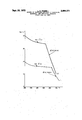
- the diagram of the appended drawing shows the improvide strength which the mentioned high-creep strength austenitic steel acquires by means of the procedure according to the invention.
- the curves in the diagram illustrate the minimum yield point (min. 00.2) respectively the creep rupture strength at 100.000 hours (acB/ 100.00) for the steels at temperatures between 200 and 700 C.
- the yield strength and the creep rupture strength represent the normally used data for design calculations, the yield strength at temperatures below the intersection of the respective strength values and the creep rupture strength above the mentioned point of intersection. From the curves in the diagram it is evident that the yield strength as well as the creep rupture strength, is increased by practicing the described procedure, the first one about This means a considerably increased possibility to use the austenitic steels as a strength-supporting component in a composite material in particular in the earliermentioned temperature range of 300550 C.
- austenitic stainless steels of the high-temperature strength type As an example of this kind of steel the following analysis may be mentioned: 0.030.20% C; up to 1% Si; 0.2-3% Mn; 14-20% Cr; 12.5-35% Ni; 0.3- 0.8% Ti; 0.2-1.7% Mo; 0.002-0.020% B; up to 0.5% V
- W, Nb and/or Ta up to 1% Co; at the most 0.5% Cu; up to 0.2% Ce and/or Zr and the rest iron with insignificant amounts of impurities.
- the ferritic stainless steel may-except iron with insignificant amounts of impurities-contain: 0.03-0.10% C; for instance 0.06% C; 1'0-14% Cr; up to 1% Si; up to 1% Mn; up to 1% Tifor instance, 03-06% Ti; up to 1.5 Ta and/or Nb, for instance 0.61.2% Ta and/or Nb; and up to 3% Al, for instance 0.51.5% Al.
- EXAMPLE '1 In the manufacture of tubes for steam generators and superheaters there were used composite tube billets composed of austenitic stainless steel standard steel ATSI 316 (SIS 2343) and a ferritic stainless 13 percent chromium steel, possibly containing additions of further alloying elements as Al, Ti, Nb and/ or Ta.
- the billet was hotextruded and cold-rolled to tubes with an outer diameter of 27 mm. and a W311i thioknes of 3.5 mm., of which 3 mm. was the layer of austenitic steel and 0.5 mm. was the layer of ferritic steel.
- the cold-rolling was followed by solution heat-treatment at 1060 C. and fast cooling. Then the wall thickness was reduced 10% by cold-working.
- the article was annealed at 750 C. by which treatment the ferritic layer obtained by recrystallization a finegrained structure with a mean grain area of about 400 1 while no recrystallization occurred in the austenitic layer, which latter maintained the high yield strength and creep strength obtained through the cold-rolling.
- EXAMPLE 2 The manufacturing was performed according to Example 1 with the difference that the tubes, after the 10 percent reduction by cold-working, were cold-bent the U-bends, after which the total reduction in the bends were at the most 25%.
- Composite tubes for the purpose mentioned in Example 1 were made of a composite material consisting of high-temperature strength austenitic steel with the composition: O.10% C; 0.4% Si; 1.8% Mn; 15% Cr; 15% Ni; 1.2% Mo; 0.45% Ti; 0.006% B and the rest iron, and a ferritic chromium steel with the composition: 0.06% C; 0.3% Mn; 12% Cr; 0.45% Ti; 1.0% A1 and the rest iron. After hot-extrusion and cold-rolling, quenching from 1150" C. was effected.
- Method of making a tube, strip or plate article of composite material for use at high temperatures and consisting of a supporting layer of austenitic stainless steel which on at least one side is bonded to an outer layer of ferritic stainless steel having high resistance to stress corrosion comprising the steps of forming a composite billet of said austenitic and ferritic stainless steels; heat-treating the billet of composite material in a normal way for austenitic steel, said heat-treatment including solution heat treatment followed by fast cooling, cold-working and finally heat-treating the resulting article at such a temperature that only the ferritic steel is recrystallized.
- the austenitic steel is a high-temperature steel containing at the least 14% chromium and at the lowest 8% nickel, whilst the ferritic steel is resistant to halogen-induced stress corrosion and has a chromium content of less than 14%.
- the austenitic steel consists of 0.03-0.20% carbon; at the most 1% silicon; 0.2-3% manganese; 14-20% chromium; 12.5- 35% nickel; 0.30.8% titanium; 0.2-l.7% molybdenum; 0.-002-0.020% boron; at the most 0.5% vanadium, tungsten, niobium and/or tantalum; at the most 1% cobalt; at the most 0.5 copper and at the most 0.2% each of cerium and/or zirconium, balance iron and insignificant amounts of impurities, which austenitic steel is firmly bonded to a layer of ferritic steel.
- the ferritic steel contains 1014% chromium, up to 3% aluminum, up to 1% titanium and up to 1.5% niobium and/ or tantalum.
Landscapes
- Chemical & Material Sciences (AREA)
- Engineering & Computer Science (AREA)
- Mechanical Engineering (AREA)
- Materials Engineering (AREA)
- Metallurgy (AREA)
- Organic Chemistry (AREA)
- Physics & Mathematics (AREA)
- Thermal Sciences (AREA)
- Crystallography & Structural Chemistry (AREA)
- Heat Treatment Of Steel (AREA)
- Pressure Welding/Diffusion-Bonding (AREA)
Abstract
A DUPLEX METAL ARTICLE, FOR HIGH-TEMPERATURE USE, CONSISTING OF A HIGH-STRENGHT AUSTENTIC STAINLESS STEEL AND A LAYER OF FERRITIC STAINLESS STEEL HAVING HIGH RESISTANCE TO STRESS CORROSION IS PRODUCED BY THE STEPS OF FORMING A COMPOSITE BILLET OF THE TWO METALS, HEAT-TREATING THE BILLET IN THE WAY NORMAL FOR AUSTENITIC STEEL, COLD-WORKING THE BILLET, AND HEAT-TREATING THE RESULTING ARTICLE AT SUCH A TEMPERATURE THAT ONLY THE FERRITIC STEEL IS RE-CRYSTALLIZED.
Description
Sept. 26, 1972 L. O. EGNELL METHOD OF PRODUCING ARTICLES OF COMPOSITE MATERIAL, AND RESULTING PRODUCTS Filed June 11, 1971 min 6 02 x o 200 360 1.60 560 660 V 760 fc United States Patent US. Cl. 148-12 Claims ABSTRACT OF THE DISCLOSURE A duplex metal article, for high-temperature use, consisting of a high-strength austenitic stainless steel and a layer of ferritic stainless steel having high resistance to stress corrosion is produced by the steps of forming a composite billet of the two metals, heat-treating the billet in the way normal for austenitic steel, cold-working the billet, and heat-treating the resulting article at such a temperature that only the ferritic steel is re-crystallized.
The present invention relates to a method of producing duplex metal articles (i.e., articles of composite materials) for use at high temperatures and consisting of,
a supporting intermediate layer of austenitic stainless steel which on at least one and usually on both sides is covered with outer layers of ferritic stainless steel having high resistance to stress corrosion. The invention also includes objects such as tubing, strip and plate manufactured according to the method.
Austenitic stainless steels have good general resistance to corrosion and, as a rule, at higher temperatures also high creep strength. At temperatures above about 100 C., the fitness for use of these steels is restricted, however, because of the susceptibility to halogen-induced stress corrosion. In steam generators and superheaters, for example, there is a certain enrichment of chlorides on the tube surfaces where water evaporation occurs. In tubes of austenitic steel the consequence will be stress corrosion attack. Accordingly, a careful water control is a pre-requisite for the use of austenitic stainless steel in such cases. In spite of these measures, the risks of developing such stress corrosion has to be regarded as considerable, particularly in the temperature range of BOO-550 C.
A solution of the above-mentioned problem would involve manufacturing of a composite material consisting of a supporting layer of austenitic stainless steel which on one or both sides is supplied with outer layers of ferritic stainless steel having high resistance to stress corrosion. For example a tube, manufactured of such composite material having the ferritic layer along the interior surface, should in that may be protected against stress corrosion at the mentioned surface.
It has been found, however, that the desired favorable properties in articles of the above-mentioned composite material cannot be obtained except when observing a special method of manufacture adapted to the metallic properties of the two materials.
Only by the invention has it been possible to make objects of such composite material with desired favorable properties in the mentioned (and other) respects, including a considerably increased strength of the austenitic component at elevated temperatures and a favorable fine grained structure of the ferritic component.
The supporting layer of austenitic stainless steel in the composite material is preferably chosen among the high temperature steels with high creep strength, and should contain at the lowest 14% chromium and at the lowest 8% nickel; the layer (or the layers) of ferritic 3,694,271 Patented Sept. 26, 1972 stainless steel, on the other hand, consists of a steel-resistant to halogen induced stress corrosion-having a chromium content below 14%. As examples of material combinations may be mentioned a supporting layer of an austenitic steel of the type containing about 18% Cr, 12% Ni and 2.5% Mo, combined with a layer of a ferritic steel containing about 13% Cr. A similar combination is a supporting layer of an austenitic steel containing about 15% Cr, 15% Ni, 1.2% Mo and 0.4% Ti, combined with a covering layer or layers of a ferritic steel containing about 12% Cr, 1% Al and 0.4% Ti.
It is often suitable to choose such a composition of the ferritic steel that it shall not become hardened in connection with welding and also not be embrittled after long time use because of socalled 475 C.-embrittlement. In the last-mentioned respect, additions of Al up to 3%-for instance, between O.5-2%have been found to prevent 475 C.-embrittlement.
Another critical condition precedent for the use of the composite material at high temperatures is that contact between the components (i.e., layers) shall not be lost. This makes necessary a metallurgical bond, attained by some kind of hot working, for instance, rolling or extrusion.
The present invention principally relates to a method of manufacturing articles of the above-described composite material in which method the finishing, workingand heat-treating operations have been adjusted so that the desired, favorable properties are attained in the austenitic component as well as in the ferritic component.
One of the conditions precedent is that the austenitic stainless steel shall be the strength supporting component and that the chosen heat-treatment conditions shall give optimum strength. The normally occurring heat-treatment is quenching from a temperature above 1000 C., for instance 1050 C. For certain austenitic steels the quenching is done from temperatures above 1050 C. in order to give high creep strength.
If the quenching is performed from above-mentioned temperatures the layer of ferritic stainless steel-which should be thinner than the layer of strength-supporting austenitic steel-will acquire a coarse structure, which is characterized by large grains. Such a structure has low ductility, which characteristic has been found to be very unfavorable.
Because the thermal expansion properties of the respective materials are very different-the ferritic material expands much more than does the austenitic-the thinner ferritic layer is exposed to strain fatigue at normally present temperature variations during operation conditions causing crack-formation in case of a coarse structure. The tendency to cracking is dependent on the structure and will begin earlier the coarser is the structure.
It is, therefore, essential to produce a fine-grained struc-= ture in the ferritic material. This also causes the material to have improved corrosion-resistance properties.
A more fine grained, more ductile, structure in the ferritic steeland, at the same time, an essentially improved strength in the austenitic steel-are attained according to the invention by cold working a billet of the composite material, after quenching from normal temperature for austenitic steels, and then heat-treating at such a temperature that only the ferritic steel recrystallizes.
After the quenching, which is usually done from a temperature above 1000 C., for instance between 1030- 1230 C., but before the cold-working, the austenitic steel has good creep strength at the same time as the yield strength is relatively low, while the layer of ferritic steel has acquired the mentioned unfavorable coarse structure. In the cold-working the cross-sectional area of the billet of the composite material shall be reduced between 5- 70%, preferably between -45%. By this operation the yield strength of the austenitic steel is raised very much even at low reductions, at the same time as its creep strength, also is increased. For the ferritic steel, particularly if it is all ferritic, containing for instance titanium, aluminum, niobium and/or tantalum, the ensuing coldrolling makes a recrystallization possible at the following heat-treatment, which heat-treatment is performed as an annealing at a temperature between 650-950 C., preferably between 700-850 C. By this heat-treatment the ferritic steel acquires the desired favorable fine-grained structure whilst the risk of intergranular corrosion after, for instance, welding is decreased; at the same time, the austenitic steel only undergoes a recovery, meaning that the internal stresses in it are somewhat reduced.
The method according to the invention leads to a recrystallized fine-grained structure in the ferritic component as well as very high strength in the austenitic component mainly because of the great increase in yield strength.
It may be mentioned that the cold-working in the manufacture of tubes of the composite material is preferably done by drawing, rolling and/or bending, at which the bending may be performed in connection with the tube manufacturing or with the production of heat exchangers or the like articles.
It may be mentioned further, that the coarse structure of the ferritic steel after the quenching shows grains with a mean grain area in the order of 2000 (square microns). The mean grain area of the fine-grained structure of the steel after the recrystallization annealing may for instance be between 300600,u
The advantages which are obtained by the described method and the conditions precedent for its accomplishment will be fore specifically described in the following, taken in connection with the showing in the appended drawing, in which the single figure is a diagrammatic showing of strength improvements realized by following the concepts of the present invention.
A composite material consisted of a supporting layer of an austenitic steel of the type AISI 321 (SIS 2337) containing 0.07% C; 0.6% Si; 1.5% Mn; 17.5% Cr; 10.5% Ni; 0.4% Ti and the rest mainly iron, provided with a surface layer of a steel resistant to stress corrosion, said layer consisting of a ferritic 13 percent chromium steel with the composition: 0.04% C; 0.3% Si; 0.3% Mn; 13% Cr and the rest mainly iron. After quenching from about 1060 C. the composite material showed quite normal properties concerning the austenitic component while the ferritic component had acquired a coarse structure with a mean grain area equivalent to about 200013. The quenching was followed by a cold-working procedure in which the cross-sectional area of the material was reduced By means of the cold-working the yield strength of the austenitic steel was substantially increased. Finally, the material was annealed at a temperature between 700-800 C. By this expedient the ferritic steel recrystallized and acquired a fine-grained structure with a mean grain area of about 500,41 while the austenitic steel maintained the increased strength attained by the coldworking without recrystallizing. For a composite material with the mentioned components and an annealing temperature between 700-800 C. it has been found necessary that the reduction must not exceed 30% if the effect according to the invention should be obtained. The reason therefore is that the recrystallization temperature of the austenitic component decreases at increasing degree of cold-working.
If the composite material is chosen from a high temperature strength austenitic steel of the type 0.10% C; 0.4% Si; 1.8% Mn; Cr; 15% Ni; 1.2% Mo; 0.45% Ti; 0.006% B and the rest mainly iron, with a surface layer resistant to stress corrosion in a 13 percent ferritic chromium steel, for example of the earlier mentioned kind or in a ferritic chromium steel of the type 0.06% C; 0.3% Si; 0.3% Mn; 12% Cr; 0.45% Ti; 1.0% A1 and the rest mainly iron, the conditions precedent for the method will be changed in comparison with the preceding case because the high creep strength austenitic steel has a considerably higher recrystallization temperature than has the austenitic steel of the type AISI 321 (SIS 2337). After quenching at 1100 C. and 30% reduction of the cross-sectional area by means of cold-working, the recrystallization temperature of the austenitic component is about 850 C. At higher degrees of reduction the recrystallization temperature of this component gradually decreases. Thus if the recrystallization annealing of the ferritic component is performed at 700 (3., the reduction of the cross-sectional area of the mentioned composite material by cold-working must not exceed about 60% if the recrystallization of the austenitic component shall be avoided. The use of high creep strength austenitic steel thus ensures greater margins concerning the degree of cold-working and the recrystallization temperature in the accomplishment of the method according to the invention. An additional improvement in the mentioned respect can be obtained by increasing the quench annealing temperature. If this is increased from 1100 to 1150 C., a corresponding rise in the recrystallization temperature of the mentioned high-creep strength austenitic steel occurs at the same time.
The diagram of the appended drawing shows the improvide strength which the mentioned high-creep strength austenitic steel acquires by means of the procedure according to the invention. The curves in the diagram illustrate the minimum yield point (min. 00.2) respectively the creep rupture strength at 100.000 hours (acB/ 100.00) for the steels at temperatures between 200 and 700 C.
From curve 1 the result after merely quenching from 1150" C. is evident, whilst from curve 2 the result after quenching from 1150 C. followed by a 20% reduction of the cross-sectional area by means of cold-working and recovery annealing about 1 hour at 800 C. The annealing temperature and time were adjusted to the recrystallization of the ferritic steel in the composite material.
The yield strength and the creep rupture strength represent the normally used data for design calculations, the yield strength at temperatures below the intersection of the respective strength values and the creep rupture strength above the mentioned point of intersection. From the curves in the diagram it is evident that the yield strength as well as the creep rupture strength, is increased by practicing the described procedure, the first one about This means a considerably increased possibility to use the austenitic steels as a strength-supporting component in a composite material in particular in the earliermentioned temperature range of 300550 C.
In the manufacture of composite material according to the invention it is, as mentioned earlier, often suitable to choose austenitic stainless steels of the high-temperature strength type. As an example of this kind of steel the following analysis may be mentioned: 0.030.20% C; up to 1% Si; 0.2-3% Mn; 14-20% Cr; 12.5-35% Ni; 0.3- 0.8% Ti; 0.2-1.7% Mo; 0.002-0.020% B; up to 0.5% V
W, Nb and/or Ta; up to 1% Co; at the most 0.5% Cu; up to 0.2% Ce and/or Zr and the rest iron with insignificant amounts of impurities.
The ferritic stainless steel may-except iron with insignificant amounts of impurities-contain: 0.03-0.10% C; for instance 0.06% C; 1'0-14% Cr; up to 1% Si; up to 1% Mn; up to 1% Tifor instance, 03-06% Ti; up to 1.5 Ta and/or Nb, for instance 0.61.2% Ta and/or Nb; and up to 3% Al, for instance 0.51.5% Al.
In the following, some examples are mentioned concerning the manufacture of composite tubes by application of the procedure according to the invention.
EXAMPLE '1 In the manufacture of tubes for steam generators and superheaters there were used composite tube billets composed of austenitic stainless steel standard steel ATSI 316 (SIS 2343) and a ferritic stainless 13 percent chromium steel, possibly containing additions of further alloying elements as Al, Ti, Nb and/ or Ta. The billet was hotextruded and cold-rolled to tubes with an outer diameter of 27 mm. and a W311i thioknes of 3.5 mm., of which 3 mm. was the layer of austenitic steel and 0.5 mm. was the layer of ferritic steel. The cold-rolling was followed by solution heat-treatment at 1060 C. and fast cooling. Then the wall thickness was reduced 10% by cold-working. Finally, the article was annealed at 750 C. by which treatment the ferritic layer obtained by recrystallization a finegrained structure with a mean grain area of about 400 1 while no recrystallization occurred in the austenitic layer, which latter maintained the high yield strength and creep strength obtained through the cold-rolling.
EXAMPLE 2 The manufacturing was performed according to Example 1 with the difference that the tubes, after the 10 percent reduction by cold-working, were cold-bent the U-bends, after which the total reduction in the bends were at the most 25%.
EXAMPLE 3 Composite tubes for the purpose mentioned in Example 1 were made of a composite material consisting of high-temperature strength austenitic steel with the composition: O.10% C; 0.4% Si; 1.8% Mn; 15% Cr; 15% Ni; 1.2% Mo; 0.45% Ti; 0.006% B and the rest iron, and a ferritic chromium steel with the composition: 0.06% C; 0.3% Mn; 12% Cr; 0.45% Ti; 1.0% A1 and the rest iron. After hot-extrusion and cold-rolling, quenching from 1150" C. was effected. Then the tubes were coldworked along their whole length by drawing, by which measure the cross-sectional area was reduced about 10%, and finally there was an annealing for 1 hour at a temperature between 75 -800 C. By this treatment the layer of austenitic material acquired a yield strength (00.2) at 500 C. of 40 kg./mm. The ferritic material recrystallized completely and acquired a mean grain size of about 500u EXAMPLE 4 Composite tubes with a composition according to any of the Examples 1 and 3 were cold-worked (after quenching) along their whole length by drawing and by bending in connection with the manufacture of heat exchangers or similar articles in which the tubes were supposed to be used. The total deformation was at least The final annealing occurred (as before) at a temperature between 750800 C.
I claim:
1. Method of making a tube, strip or plate article of composite material for use at high temperatures and consisting of a supporting layer of austenitic stainless steel which on at least one side is bonded to an outer layer of ferritic stainless steel having high resistance to stress corrosion, said method comprising the steps of forming a composite billet of said austenitic and ferritic stainless steels; heat-treating the billet of composite material in a normal way for austenitic steel, said heat-treatment including solution heat treatment followed by fast cooling, cold-working and finally heat-treating the resulting article at such a temperature that only the ferritic steel is recrystallized.
2. Method according to claim 1, wherein the final heat treatment for the recrystallization of the ferritic steel is performed by annealing at a temperature between 650- 950" C.
3. Method according to claim 1, wherein the final heat treatment for the recrystallization of the ferritic steel is performed by annealing at a temperature between 700- 850 C.
4. Method according to claim 1, in which the solution heat-treatment is effected at a temperature above 1000 C.
5. Method according to claim 1, in which the crosssectional area is reduced by an amount between 570% in the cold working.
6. Method according to claim 1, in which the crosssectional area is reduced by an amount between 545% in the cold working.
7. Method according to claim 1, wherein the austenitic steel is a high-temperature steel containing at the least 14% chromium and at the lowest 8% nickel, whilst the ferritic steel is resistant to halogen-induced stress corrosion and has a chromium content of less than 14%.
8. Method according to claim 1, wherein the austenitic steel consists of 0.03-0.20% carbon; at the most 1% silicon; 0.2-3% manganese; 14-20% chromium; 12.5- 35% nickel; 0.30.8% titanium; 0.2-l.7% molybdenum; 0.-002-0.020% boron; at the most 0.5% vanadium, tungsten, niobium and/or tantalum; at the most 1% cobalt; at the most 0.5 copper and at the most 0.2% each of cerium and/or zirconium, balance iron and insignificant amounts of impurities, which austenitic steel is firmly bonded to a layer of ferritic steel.
9. Method according to claim 1, in which the ferritic steel contains 1014% chromium, up to 3% aluminum, up to 1% titanium and up to 1.5% niobium and/ or tantalum.
10. Method according to claim 1, in which the initial billet of the composite material is formed by hot-working as extrusion or rolling.
References Cited UNITED STATES PATENTS 2,306,421 12/ 1942 Arness 29-1966 X 2,759,249 8/1956 Eben-1e 29-1961 2,764,805 '10/1956 Mears 29-196.1 2,769,227 11/ 1956 Sykes et a1. 29196.6 X 3,323,953 6/1967 Lesney 148-12 X CHARLES N. LOVELL, Primary Examiner US. Cl. X.R.
Applications Claiming Priority (1)
| Application Number | Priority Date | Filing Date | Title |
|---|---|---|---|
| SE7009045A SE334908C (en) | 1970-06-30 | 1970-06-30 | PROCEDURES FOR THE PREPARATION OF COMPOUND MATERIAL FOR USE AT HIGH TEMPERATURES |
Publications (1)
| Publication Number | Publication Date |
|---|---|
| US3694271A true US3694271A (en) | 1972-09-26 |
Family
ID=20275685
Family Applications (1)
| Application Number | Title | Priority Date | Filing Date |
|---|---|---|---|
| US152156A Expired - Lifetime US3694271A (en) | 1970-06-30 | 1971-06-11 | Method of producing articles of composite material,and resulting products |
Country Status (7)
| Country | Link |
|---|---|
| US (1) | US3694271A (en) |
| JP (1) | JPS524502B1 (en) |
| CH (1) | CH558833A (en) |
| DE (1) | DE2129135B2 (en) |
| FR (1) | FR2099200A5 (en) |
| GB (1) | GB1350831A (en) |
| SE (1) | SE334908C (en) |
Cited By (9)
| Publication number | Priority date | Publication date | Assignee | Title |
|---|---|---|---|---|
| US3867212A (en) * | 1972-03-16 | 1975-02-18 | Texas Instruments Inc | Composite material, tubing made from the material, and methods for making the material and tubing |
| US3891820A (en) * | 1971-08-25 | 1975-06-24 | Siemens Ag | Weld-plating of steel |
| US4421572A (en) * | 1982-03-18 | 1983-12-20 | The United States Of America As Represented By The United States Department Of Energy | Thermomechanical treatment of alloys |
| US4443406A (en) * | 1982-01-22 | 1984-04-17 | Hitachi, Ltd. | Heat-resistant and corrosion-resistant weld metal alloy and welded structure |
| US4463061A (en) * | 1982-06-11 | 1984-07-31 | Nippon Steel Corporation | Boiler tube having improved high temperature mechanical strength, improved high temperature corrosion resistant property and resistance to embrittlement during service |
| US4973524A (en) * | 1988-05-25 | 1990-11-27 | Vdm Nickel-Technologie Aktiengesellschaft | Laminated composite coins and method thereof |
| US5207776A (en) * | 1991-10-04 | 1993-05-04 | The Babcock & Wilcox Company | Bi-metallic extrusion billet preforms and method and apparatus for producing same |
| EP3162558A1 (en) * | 2015-10-30 | 2017-05-03 | Outokumpu Oyj | Component made of metallic composite material and method for the manufacture of the component by hot forming |
| CN110214081A (en) * | 2017-01-30 | 2019-09-06 | 蒂森克鲁伯股份公司 | Steel compound with uneven property distribution |
Families Citing this family (1)
| Publication number | Priority date | Publication date | Assignee | Title |
|---|---|---|---|---|
| CN112281064A (en) * | 2020-10-27 | 2021-01-29 | 郑州煤机智能工作面科技有限公司 | Low-alloy high-strength steel plate forging for high-strength structure and forging method |
-
1970
- 1970-06-30 SE SE7009045A patent/SE334908C/en unknown
-
1971
- 1971-06-11 DE DE19712129135 patent/DE2129135B2/en not_active Withdrawn
- 1971-06-11 US US152156A patent/US3694271A/en not_active Expired - Lifetime
- 1971-06-18 FR FR7122184A patent/FR2099200A5/fr not_active Expired
- 1971-06-18 GB GB2877671A patent/GB1350831A/en not_active Expired
- 1971-06-25 CH CH939771A patent/CH558833A/en not_active IP Right Cessation
- 1971-06-29 JP JP46047592A patent/JPS524502B1/ja active Pending
Cited By (10)
| Publication number | Priority date | Publication date | Assignee | Title |
|---|---|---|---|---|
| US3891820A (en) * | 1971-08-25 | 1975-06-24 | Siemens Ag | Weld-plating of steel |
| US3867212A (en) * | 1972-03-16 | 1975-02-18 | Texas Instruments Inc | Composite material, tubing made from the material, and methods for making the material and tubing |
| US4443406A (en) * | 1982-01-22 | 1984-04-17 | Hitachi, Ltd. | Heat-resistant and corrosion-resistant weld metal alloy and welded structure |
| US4421572A (en) * | 1982-03-18 | 1983-12-20 | The United States Of America As Represented By The United States Department Of Energy | Thermomechanical treatment of alloys |
| US4463061A (en) * | 1982-06-11 | 1984-07-31 | Nippon Steel Corporation | Boiler tube having improved high temperature mechanical strength, improved high temperature corrosion resistant property and resistance to embrittlement during service |
| US4973524A (en) * | 1988-05-25 | 1990-11-27 | Vdm Nickel-Technologie Aktiengesellschaft | Laminated composite coins and method thereof |
| US5207776A (en) * | 1991-10-04 | 1993-05-04 | The Babcock & Wilcox Company | Bi-metallic extrusion billet preforms and method and apparatus for producing same |
| EP3162558A1 (en) * | 2015-10-30 | 2017-05-03 | Outokumpu Oyj | Component made of metallic composite material and method for the manufacture of the component by hot forming |
| CN108349213A (en) * | 2015-10-30 | 2018-07-31 | 奥托库姆普有限公司 | Component made of metallic composite material and method for producing component by thermoforming |
| CN110214081A (en) * | 2017-01-30 | 2019-09-06 | 蒂森克鲁伯股份公司 | Steel compound with uneven property distribution |
Also Published As
| Publication number | Publication date |
|---|---|
| DE2129135A1 (en) | 1972-03-16 |
| SE334908B (en) | 1971-05-10 |
| JPS524502B1 (en) | 1977-02-04 |
| CH558833A (en) | 1975-02-14 |
| FR2099200A5 (en) | 1972-03-10 |
| SE334908C (en) | 1980-07-07 |
| GB1350831A (en) | 1974-04-24 |
| DE2129135B2 (en) | 1972-03-16 |
Similar Documents
| Publication | Publication Date | Title |
|---|---|---|
| EP1431407B1 (en) | Steel plate exhibiting excellent workability and method for producing the same | |
| EP3219820B1 (en) | Nickel-base alloy-clad steel plate and method for producing the same | |
| US4994118A (en) | Process for the production of hot rolled steel or heavy plates | |
| US20080035248A1 (en) | Method Of Producing Austenitic Iron/Carbon/Manganese Steel Sheets Having Very High Strength And Elongation Characteristics Ans Excellent Homogeneity | |
| US3556776A (en) | Stainless steel | |
| JP5181496B2 (en) | Structural high-strength thick steel plate with excellent brittle crack propagation stopping characteristics and method for producing the same | |
| CA1058425A (en) | Pitting resistant stainless steel alloy having improved hot-working characteristics | |
| US3694271A (en) | Method of producing articles of composite material,and resulting products | |
| AU2020413417B2 (en) | Alloy | |
| KR20230098875A (en) | Manufacturing method of austenitic stainless steel strip | |
| US3278298A (en) | Chromium-nickel-aluminum steel and method | |
| US3957544A (en) | Ferritic stainless steels | |
| US4545826A (en) | Method for producing a weldable austenitic stainless steel in heavy sections | |
| JP5061649B2 (en) | Thick steel plate with a thickness of 50 mm or more with excellent brittle crack propagation stopping characteristics | |
| JPH0636993B2 (en) | Method for producing stainless clad steel sheet with excellent corrosion resistance and toughness | |
| US2416515A (en) | High temperature alloy steel and articles made therefrom | |
| JPH08296000A (en) | Ferritic stainless steel excellent in workability and corrosion resistance and method for producing the same | |
| US4043838A (en) | Method of producing pitting resistant, hot-workable austenitic stainless steel | |
| KR20250167659A (en) | Method for manufacturing clad steel plates | |
| JP2008111165A (en) | Structural high-strength thick steel plate with excellent brittle crack propagation stopping characteristics and method for producing the same | |
| JP2662485B2 (en) | Steel sheet having good low-temperature toughness and method for producing the same | |
| JP2004323966A (en) | Steel plate excellent in earthquake resistance and weldability and manufacturing method thereof | |
| JP3297010B2 (en) | Manufacturing method of nearβ type titanium alloy coil | |
| JPH05179378A (en) | Ni-based alloy with excellent room temperature and high temperature strength | |
| JPH0713252B2 (en) | Method for producing high strength austenitic stainless steel with excellent seawater resistance |
Legal Events
| Date | Code | Title | Description |
|---|---|---|---|
| AS | Assignment |
Owner name: SANTRADE LTD., ALPENQUAI 12, CH-6002, LUCERNE, SWI Free format text: ASSIGNMENT OF ASSIGNORS INTEREST.;ASSIGNOR:SANDVIK AKTIEBOLAG, A CORP. OF SWEDEN;REEL/FRAME:004085/0132 Effective date: 19820908 |