US3693602A - Internal combustion engine with sound-proofing casing - Google Patents
Internal combustion engine with sound-proofing casing Download PDFInfo
- Publication number
- US3693602A US3693602A US72350A US3693602DA US3693602A US 3693602 A US3693602 A US 3693602A US 72350 A US72350 A US 72350A US 3693602D A US3693602D A US 3693602DA US 3693602 A US3693602 A US 3693602A
- Authority
- US
- United States
- Prior art keywords
- casing
- cooling
- exhaust pipe
- sound
- internal combustion
- Prior art date
- Legal status (The legal status is an assumption and is not a legal conclusion. Google has not performed a legal analysis and makes no representation as to the accuracy of the status listed.)
- Expired - Lifetime
Links
Images


Classifications
-
- F—MECHANICAL ENGINEERING; LIGHTING; HEATING; WEAPONS; BLASTING
- F02—COMBUSTION ENGINES; HOT-GAS OR COMBUSTION-PRODUCT ENGINE PLANTS
- F02B—INTERNAL-COMBUSTION PISTON ENGINES; COMBUSTION ENGINES IN GENERAL
- F02B77/00—Component parts, details or accessories, not otherwise provided for
- F02B77/11—Thermal or acoustic insulation
- F02B77/13—Acoustic insulation
-
- F—MECHANICAL ENGINEERING; LIGHTING; HEATING; WEAPONS; BLASTING
- F02—COMBUSTION ENGINES; HOT-GAS OR COMBUSTION-PRODUCT ENGINE PLANTS
- F02B—INTERNAL-COMBUSTION PISTON ENGINES; COMBUSTION ENGINES IN GENERAL
- F02B2275/00—Other engines, components or details, not provided for in other groups of this subclass
- F02B2275/34—Lateral camshaft position
-
- F—MECHANICAL ENGINEERING; LIGHTING; HEATING; WEAPONS; BLASTING
- F02—COMBUSTION ENGINES; HOT-GAS OR COMBUSTION-PRODUCT ENGINE PLANTS
- F02B—INTERNAL-COMBUSTION PISTON ENGINES; COMBUSTION ENGINES IN GENERAL
- F02B3/00—Engines characterised by air compression and subsequent fuel addition
- F02B3/06—Engines characterised by air compression and subsequent fuel addition with compression ignition
Landscapes
- Engineering & Computer Science (AREA)
- Physics & Mathematics (AREA)
- Acoustics & Sound (AREA)
- Chemical & Material Sciences (AREA)
- Combustion & Propulsion (AREA)
- Mechanical Engineering (AREA)
- General Engineering & Computer Science (AREA)
- Exhaust Silencers (AREA)
Abstract
A sound-proofed internal combustion engine having a casing spaced around the engine and having a cooling-air blower driven by the engine arranged inside the casing with inlet and outlet in the casing and an exhaust pipe extending through the casing and exposed to the cooling-air stream of the blower to produce both a sound proofing and heat absorbing effect.
Description
.[22] Filed:
United States Patent I Thien et a1.
[54] INTERNALCOMBUSTION ENGINE WITH SOUND-PROOFING CASING [72] inventors: Gerhard Thien; Heinz Fachbach,
both of Graz, Austria 73 Assign: Hans List, GraZ, Austria Sept. 15,1970 21 Appl.No.:72,350
[30] I Foreign Application Priority Data [58] Field of Search ..123/195 P, 195 C, 198 E, 41.7; 60/31; l81/33.4
[56] References Cited UNITED STATES PATENTS 10/1939 Bracken et a1. ..123/198 E 8/1964 Horning et a1 ..123/41.7
[451 Sept. 26, 1972 3,155,082 11/1964 Roorda et a1 ..123 /198 E 3,521,726 7/1970 Freyn ..123/195 C 2,204,294 6/ 1940 Blanchard ..60/31 X 3,431,882 3/1969 Irgens ..l23/l95 P 2,067,253 1/1937 Wohanka ..60/31 3,530,840 9/1970 Freyn ..123/195 C FOREIGN PATENTS OR APPLICATIONS 1,203,837 9/1970 Great Britain 123/41.7
Primary Examiner-Laurence M. Goodridge Attorney-Watson, Cole, Grindle & Watson [5 7] ABSTRACT A sound-proofed internal combustion engine having a casing spaced around the engine and having a coolingair blower driven by the engine arranged inside the casing with inlet and outlet in the casing and an exhaust pipe extending through the casing and exposed to the cooling-air stream of the blower to produce both a sound proofing and heat absorbing effect.
3 Claims, 4 Drawing Figures I 12 u i casing and driven by means of the internal combustion engine, at least one inlet and one outlet each preferably provided inside the casing for the cooling air delivered by the blower, and an exhaust pipe extending through the said casing.
Internal combustion engines of this type which are at least partly encased for the purpose of reducing noise radiation, usually require additionalcooling, particularly for the oil-wetted wall members and for such auxiliary machines of the engine as are located inside the casing, in order to compensate for the reduction of heat radiation caused by the casing by means of the transfer of heat to the cooling air passing through the casing. Thus overheating of such parts of the internal combustion engine as are subject to a particularly high thermal stress is avoided and the provision of an oil-cooler of ordinary size is amply sufficient.
A problem which has not as yet been solved in a satisfactory manner arises in connection with similar types of sound-proofed internal combustion engines with regard to the location and design of the exhaust piping. Apart from radiating a substantial amount of heat, the exhaust piping with its bends and pipes is a considerable source of objectionable sounds which, unless provided with adequate screening, is liable to cancel at least part of the sound-proofing effect of the encasing out again.
It is the object of the present invention to eliminate the shortcomings of internal combustion engines of the type hereabove described by providing for a special both acoustically and thermally satisfactoryarrangement and design of the exhaust piping. According to the invention, the exhaust piping is directly exposed to the cooling-air stream of the blower at and/or in front of the point where it extends through the casing and traverses the casing in such a manner as to produce a sound-and-heat-absorbing effect. By these means local overheating of structural elements of the casing adjoining the exhaust piping is avoided and sound radiation from the external surfaces of the pipes and bends of the exhaust piping is reduced to the minimum. In this connection, the cooling-air stream inside the casing is preferably concentrated on the portions of the exhaust system requiring cooling by the provision of adequate fixtures. In order to improve the transfer of heat between the surfaces of the exhaust system requiring cooling and the cooling air passing thereabove, it is possible to increase the velocity of flow in those areas.
" According to another embodiment of the invention it is possible to provide cooling ribs at least on part of the exhaust piping extending inside the casing, particularly on the exhaust manifold. This augmentation of the cooling surfaces of the section of the exhaust piping extending inside the casing is responsible for a considerable drop of temperature in the exhaust piping as a result of which the pipe temperatures prevailing at the point where the exhaust piping extends through the casing are only very moderate and easily controllable.
In one of the embodiments of the invention as hereabove described the exhaust piping is sealed by some means of heat-absorbing material at the point where it extends through the casing. This sealing means also serves to sound-proof the point where the exhaust piping extends through the casing.
It is, however, also possible according to the invention, for the exhaust piping to extend through the easing inside a preferably tubular mufiler defining an annular clearance with the exhaust piping, through which the cooling air emerges from the casing. The heat radiated by the exhaust piping is transferred to the cooling air swiftly traversing the annular clearance, as a result of which any overheating of the adjoining areas of the casing is positively avoided. The muffler may be formed by a separate member of the casingintemally lined with a sound-absorbing coating, for example, and connected with the adjacent portions of the casing, if necessary in such a manner as to be easily detachable.
According to an further feature of the invention a sound-insulating intermediate piece, preferably a corrugated tube, is inserted in the exhaust piping between the point where it is attached to the cylinder head and the point where it extends through the casing. This serves not only to restrict the passage of sound to such parts of the exhaust system as are located outside the casing, but also to reduce heat dissipation via the exhaust pipe to the outside. Where the intermediate piece is designed as a corrugated tube a larger cooling surface for the transfer of heat to the passing cooling air is available.
Finally, it is advantageously possible, according to a feature of the invention as applied to watercooled intcrnal combustion engines, to arrange the exhaust manifold in a housing traversed by the cooling water from the cylinder head, and possible integral with the cylinder head, the cooling-water return pipe of the engine emerging preferably from the said housing. Thus a sizeable portion of the heat of the exhaust gases is transferred to the cooling-water system of the internal combustion engine already in the area of the exhaust manifold, so that relatively low temperatures prevail at the point where the exhaust piping extends through the casing.
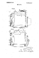
Further details of the invention will become apparent from the following description of several preferred embodiments of the invention with reference to the accompanying drawing, in which FIG. 1 shows a cross-sectional view of an internal combustion engine according to the invention on line I-I of FIG. 2,
FIG. 2 is a partial cross-sectional view of the same engine on line IIII of FIG. 1, and
FIGS. 3 and 4 each show another variant of the in ternal combustion engine according to the invention as illustrated in FIGS. 1 and 2, respectively.
The water-cooled internal combustion engine as shown in FIGS. 1 and 2 comprises a closed-type crankcase 1 with laterally spreading engine supports 2. At one extremity the crankshaft 3 of this four-cylinder inline internal combustion engine carries a vee-belt pulley v4 with an adjacent blower impeller 5. A vee-belt 6 drives the shaft 8 carrying the fan 7 by means of an additional vee-belt pulley 9.
The crankcase 1 is closed by means of an oil sump 10 tightly attached toits lower connecting flange 11. The fuel-injection pump 12 of the internal combustion engine is mounted on a side-wall 11 of the crankcase.
The internal combustion engine is provided with a sound-proofing casing comprising sound-insulating casing elements arranged around the engine in spaced relation thereto. These elements comprise a frame-like upper casing member 13 threadedly engagedor otherwise attached to the cylinder head 14 by means of flexible, sound-insulating spacers l5.
Another frame-like casing member 16 is attached to the underside of the crankcase 1 by means of sound-insulating supporting members 17.
' Between the upper casing element 13 and the lower one 16 lateral casing members 18 and 19 extend, which together with another casing member 21 located above the valve-rocker covers 20 and a casing member 22' mounted on the casing member 16 beneath the oil sump l define a closed sound-insulating housing surrounding the internal combustion engine in spaced relation thereto.
The engine supports 2 extend through the two lateral casing members 18 and 19 at openings which are sealed off by means of flexible sealing elements 22. The upwardly curved suction pipe 23 mounted on the cylinder head 14 comprises a pipe section 25 attached thereto with the interposition of a sound-insulating connecting piece 24, the said pipe section extending through an opening of the upper casing element 13.
At the front end of the casing a cooling-air inlet 26 preceded by a muffler 27 is located. The cooling-air drawn in from the blower via the opening 26 passes, as shown by arrows in the drawing, inside the casing over the external walls of the cylinder block and emerges from the casing' at the cooling-air outlet designated by reference number 28 and coated with a muffler 29.
An outstanding feature of the invention is the particular design and arrangement of the exhaust piping 30 of the internal combustion engine. In order to extend the sound-insulating measures so as to include also the exhaust system of the engine, essential parts of the exhaust piping 30 are directly exposed to the cooling-air delivered by the blower 5. For that purpose, in the design illustrated in FIGS. 1 and I 2, the exhaust manifold 31 flanged to the cylinder head 14 opposite the suction pipe 23 is provided with cooling ribs 32 and arranged inside a chamber 33 covered by the casing member 19, where a vigorous stream of cooling-air prevails.
The exhaust piping 30 is connected to the exhaust manifold 31 with the interposition of a sound-insulating intermediate piece defined by a corrugated tube 34, and extends through the casing inside a sleeve 35 attached to the casing member 19 and/or cast integral with same. At the point where the exhaust piping 30 emerges from the sleeve 35, it is surrounded by a sealing means 36 made of a heat-absorbing material. As a result of these measures, sound-radiation from the portions of the exhaust system close to the engine is considerably reduced and part of the heat of the exhaust gases is transferred to the cooling air already in the area of the exhaust manifold 31. By the sealing means 36 the point where the exhaust piping 30 extends through the casing is sealed off acoustically on the one hand, and on the other hand, the transfer of heat from the exhaust piping 30 to the casing is reduced.
Apart from several variations in casing design which are, however, not essential for the scope of the present invention, the internal combustion engine illustrated in FIGS. 3 and 4 differs from the embodiment of the in vention as hereabove described only in regard of the following details: The air-cooled exhaust manifold 31 is here replaced by the arrangement of the exhaust manifold 37 inside a housing 38 traversed by cooling water, from which the cooling-water return pipe 39 emerges. The housing 38 can also be cast integral with the cylinder head. The return pipe 39 is connected to the housing 38 with the interposition of a sound-proofing intermediate piece 40 and extends through the upper casing member 13 mounted on the cylinder head 14.
The exhaust piping 30 connected to the housing 38 by means of the corrugated tube 34 extends through a muffler 41 arranged on a lateral casing member 19, the said muffler 41 defining together with the exhaust piping 30 and annular chamber 42 through which the cooling air delivered by the blower 5 emerges from the casing system in the direction indicated by arrows in the drawing. The annular chamber 42 with the surrounding muffler 41 serves as a substitute for the cooling-air outlet 28 screened ofi by means of the muffler 29 as provided for in the first-mentioned embodiment of the invention.
In the internal combustion engine illustrated in FIGS. 3 and 4, part of the heat of the exhaust gases is transferred to the cooling-water system of the internal com bustion engine already in the area of the exhaust manifold 37. The cooling-air passing along the exhaust piping 30 inside the annular chamber 42 transfers yet another portion of the remaining heat radiated off the exhaust piping 30. Thus overheating of the adjacent parts of the casing system is avoided. The corrugated tube 34 reduces the transmission of sound to the external portions of the exhaust system. The muffler 41 positively restricts sound-radiation from the exhaust piping 30.
We claim:
1. A sound-proofed internal combustion engine comprising a sound-proofing casing arranged around the engine in spaced relation to same, a cooling-air blower driven by the internal combustion engine and arranged inside said casing, at least one inlet and one outlet in said casing provided for the passage of the cooling air delivered by said blower, an exhaust pipe extending through said casing, a sleeve mounted on said casing in the area of the point at which the exhaust pipe traverses said casing, said sleeve being formed as a muffler surrounding said exhaust pipe in spaced relation to same and defining an annular clearance together with the exhaust pipe, said annular clearance forming an outlet for the cooling air delivered by said blower, and a corrugated tube located in said exhaust pipe between the point where said exhaust pipe is attached to the engine and the point where said exhaust pipe traverses said casing, said corrugated tube forming a sound-insulating intermediate piece for said exhaust pipe.
2. An internal combustion engine according to claim 1 wherein said muffler is in the shape of a tube surrounding said exhaust pipe.
head, said exhaust pipe extending through said housing inside said cooling water chamber, and a cooling-water return pipe emerging from said housing and extending through said casing in the area of said housing.
Claims (3)
1. A sound-proofed internal combustion engine comprising a sound-proofing casing arranged around the engine in spaced relation to same, a cooling-air blower driven by the internal combustion engine and arranged inside said casing, at least one inlet and one outlet in said casing provided for the passage of the cooling air delivered by said blower, an exhaust pipe extending through said casing, a sleeve mounted on said casing in the area of the point at which the exhaust pipe traverses said casing, said sleeve being formed as a muffler surrounding said exhaust pipe in spaced relation to same and defining an annular clearance together with the exhaust pipe, said annular clearance forming an outlet for the cooling air delivered by said blower, and a corrugated tube located in said exhaust pipe between the point where said exhaust pipe is attached to the engine and the point where said exhaust pipe traverses said casing, said corrugated tube forming a sound-insulating intermediate piece for said exhaust pipe.
2. An internal combustion engine according to claim 1 wherein said muffler is in the shape of a tube surrounding said exhaust pipe.
3. An internal combustion engine according to claim 1, further comprising a cylinder-head traversed by cooling-water, a housing on said cylinder head, a cooling-water chamber located inside said housing and connected to a water-carrying chamber of said cylinder head, said exhaust pipe extending through said housing inside said cooling water chamber, and a cooling-water return pipe emerging from said housing and extending through said casing in the area of said housing.
Applications Claiming Priority (1)
| Application Number | Priority Date | Filing Date | Title |
|---|---|---|---|
| AT881969A AT301957B (en) | 1969-09-17 | 1969-09-17 | Internal combustion engine with sound-insulating casing |
Publications (1)
| Publication Number | Publication Date |
|---|---|
| US3693602A true US3693602A (en) | 1972-09-26 |
Family
ID=3608804
Family Applications (1)
| Application Number | Title | Priority Date | Filing Date |
|---|---|---|---|
| US72350A Expired - Lifetime US3693602A (en) | 1969-09-17 | 1970-09-15 | Internal combustion engine with sound-proofing casing |
Country Status (4)
| Country | Link |
|---|---|
| US (1) | US3693602A (en) |
| JP (2) | JPS4841165B1 (en) |
| AT (1) | AT301957B (en) |
| FR (1) | FR2062240A5 (en) |
Cited By (20)
| Publication number | Priority date | Publication date | Assignee | Title |
|---|---|---|---|---|
| JPS505324U (en) * | 1973-05-15 | 1975-01-21 | ||
| US3863617A (en) * | 1972-11-10 | 1975-02-04 | List Hans | Internal combustion engine with sound-proof v-belt pulley |
| JPS5052635U (en) * | 1973-09-13 | 1975-05-21 | ||
| US3949727A (en) * | 1974-05-20 | 1976-04-13 | Hans List | Carburetor engine with sound-proof encasing |
| US3951114A (en) * | 1974-03-22 | 1976-04-20 | Hans List | Cooling of internal combustion engines with sound-proof encasings |
| US3964462A (en) * | 1974-12-10 | 1976-06-22 | Hans List | Sound-proofed internal combustion engine |
| US4114714A (en) * | 1975-06-13 | 1978-09-19 | Hans List | Motor vehicle having sound-suppressing engine enclosure |
| US4126115A (en) * | 1976-09-17 | 1978-11-21 | Hans List | Internal combustion engine |
| US4141427A (en) * | 1976-09-03 | 1979-02-27 | Hans List | Motor vehicle with a noise suppressing engine encapsulation |
| USRE29923E (en) * | 1974-05-20 | 1979-03-06 | Hans List | Sound-proofed internal combustion engine |
| US4194484A (en) * | 1976-12-10 | 1980-03-25 | Hans List | Internal combustion engine having a noise suppressing encapsulation |
| US4203409A (en) * | 1977-11-23 | 1980-05-20 | Hans List | Low-noise-level internal combustion engine |
| US4257369A (en) * | 1977-09-06 | 1981-03-24 | Nissan Motor Company, Limited | Internal combustion engine equipped with noise control device |
| US4890583A (en) * | 1987-12-28 | 1990-01-02 | Fuji Jukogyo Kabushiki Kaisha | Crankcase of an engine |
| DE3929592A1 (en) * | 1989-09-06 | 1991-03-28 | Man Nutzfahrzeuge Ag | SOUND-INSULATED SHEET OIL PAN FOR INTERNAL COMBUSTION ENGINES |
| US5452693A (en) * | 1994-12-09 | 1995-09-26 | Cummins Engine Company, Inc. | Oil pan noise enclosure and attachment system for same |
| US6216658B1 (en) | 1998-06-19 | 2001-04-17 | Cummins Engine Company Ltd. | Engine cylinder block with optimized stiffness |
| US10214159B1 (en) * | 2017-09-29 | 2019-02-26 | Hyundai Motor Company | Engine compartment soundproof cover device of cab-over truck |
| US10557402B2 (en) * | 2013-03-15 | 2020-02-11 | Kohler Co. | Noise suppression systems |
| US11364955B2 (en) * | 2020-02-18 | 2022-06-21 | Mazda Motor Corporation | Engine bay structure of vehicle and method of assembling capsule cover |
Families Citing this family (6)
| Publication number | Priority date | Publication date | Assignee | Title |
|---|---|---|---|---|
| DE2547523B2 (en) * | 1975-10-23 | 1979-04-05 | Motorenfabrik Hatz Gmbh & Co Kg, 8399 Ruhstorf | Internal combustion engine with noise-dampening casing |
| AT365308B (en) * | 1977-05-06 | 1982-01-11 | List Hans | SOUND-INSULATED ENCLOSED MACHINE, IN PARTICULAR COMBUSTION ENGINE |
| AT365309B (en) * | 1977-08-18 | 1982-01-11 | List Hans | INTERNAL COMBUSTION ENGINE WITH SOUND-INSULATING PANELING |
| AT373364B (en) * | 1977-10-28 | 1984-01-10 | List Hans | INTERNAL COMBUSTION ENGINE WITH SOUND-INSULATING PANELING |
| DE3425074A1 (en) * | 1984-07-07 | 1986-01-16 | M.A.N. Maschinenfabrik Augsburg-Nürnberg AG, 8000 München | SOUND INSULATED OIL PAN FOR A TRUCK COMBUSTION ENGINE |
| JP6451805B1 (en) * | 2017-08-22 | 2019-01-16 | マツダ株式会社 | Engine heat insulation structure |
Citations (9)
| Publication number | Priority date | Publication date | Assignee | Title |
|---|---|---|---|---|
| US2067253A (en) * | 1934-05-22 | 1937-01-12 | Busch Sulzer Bros Diesel Engine Co | Engine exhaust system |
| US2177687A (en) * | 1937-11-19 | 1939-10-31 | Warner Bros | Electric generator unit |
| US2204294A (en) * | 1938-06-23 | 1940-06-11 | Eclipse Aviat Corp | Exhaust pipe |
| US3144858A (en) * | 1962-10-15 | 1964-08-18 | Inboard Marine Inc | Air-cooled inboard engine |
| US3155082A (en) * | 1962-08-13 | 1964-11-03 | Wisconsin Motor Corp | Climatic control apparatus for an air cooled engine |
| US3431882A (en) * | 1967-03-26 | 1969-03-11 | Outboard Marine Corp | Marine propulsion device |
| US3521726A (en) * | 1968-04-16 | 1970-07-28 | List Hans | Air-cooled internal combustion engine with sound-proofed sheathing |
| GB1203837A (en) * | 1968-06-25 | 1970-09-03 | Schwermaschb Nobas Veb | An internal-combustion engine housed in a closed casing for cooling and silencing purposes |
| US3530840A (en) * | 1967-02-14 | 1970-09-29 | List Hans | Soundproof internal combustion engines |
Family Cites Families (3)
| Publication number | Priority date | Publication date | Assignee | Title |
|---|---|---|---|---|
| FR1453277A (en) * | 1965-04-01 | 1966-06-03 | Couach Soc | Improvements to motor boats |
| FR1573682A (en) * | 1968-07-19 | 1969-07-04 | ||
| AT308475B (en) * | 1969-09-08 | 1973-07-10 | List Hans | Soundproof casing for internal combustion engines |
-
1969
- 1969-09-17 AT AT881969A patent/AT301957B/en not_active IP Right Cessation
-
1970
- 1970-09-15 US US72350A patent/US3693602A/en not_active Expired - Lifetime
- 1970-09-17 FR FR7033689A patent/FR2062240A5/fr not_active Expired
- 1970-09-17 JP JP45081642A patent/JPS4841165B1/ja active Pending
-
1975
- 1975-03-22 JP JP50034842A patent/JPS57165620A/en active Pending
Patent Citations (9)
| Publication number | Priority date | Publication date | Assignee | Title |
|---|---|---|---|---|
| US2067253A (en) * | 1934-05-22 | 1937-01-12 | Busch Sulzer Bros Diesel Engine Co | Engine exhaust system |
| US2177687A (en) * | 1937-11-19 | 1939-10-31 | Warner Bros | Electric generator unit |
| US2204294A (en) * | 1938-06-23 | 1940-06-11 | Eclipse Aviat Corp | Exhaust pipe |
| US3155082A (en) * | 1962-08-13 | 1964-11-03 | Wisconsin Motor Corp | Climatic control apparatus for an air cooled engine |
| US3144858A (en) * | 1962-10-15 | 1964-08-18 | Inboard Marine Inc | Air-cooled inboard engine |
| US3530840A (en) * | 1967-02-14 | 1970-09-29 | List Hans | Soundproof internal combustion engines |
| US3431882A (en) * | 1967-03-26 | 1969-03-11 | Outboard Marine Corp | Marine propulsion device |
| US3521726A (en) * | 1968-04-16 | 1970-07-28 | List Hans | Air-cooled internal combustion engine with sound-proofed sheathing |
| GB1203837A (en) * | 1968-06-25 | 1970-09-03 | Schwermaschb Nobas Veb | An internal-combustion engine housed in a closed casing for cooling and silencing purposes |
Cited By (23)
| Publication number | Priority date | Publication date | Assignee | Title |
|---|---|---|---|---|
| US3863617A (en) * | 1972-11-10 | 1975-02-04 | List Hans | Internal combustion engine with sound-proof v-belt pulley |
| JPS505324U (en) * | 1973-05-15 | 1975-01-21 | ||
| JPS528174Y2 (en) * | 1973-05-15 | 1977-02-21 | ||
| JPS5052635U (en) * | 1973-09-13 | 1975-05-21 | ||
| JPS5347700Y2 (en) * | 1973-09-13 | 1978-11-15 | ||
| US3951114A (en) * | 1974-03-22 | 1976-04-20 | Hans List | Cooling of internal combustion engines with sound-proof encasings |
| US3949727A (en) * | 1974-05-20 | 1976-04-13 | Hans List | Carburetor engine with sound-proof encasing |
| USRE29923E (en) * | 1974-05-20 | 1979-03-06 | Hans List | Sound-proofed internal combustion engine |
| US3964462A (en) * | 1974-12-10 | 1976-06-22 | Hans List | Sound-proofed internal combustion engine |
| US4114714A (en) * | 1975-06-13 | 1978-09-19 | Hans List | Motor vehicle having sound-suppressing engine enclosure |
| US4141427A (en) * | 1976-09-03 | 1979-02-27 | Hans List | Motor vehicle with a noise suppressing engine encapsulation |
| US4126115A (en) * | 1976-09-17 | 1978-11-21 | Hans List | Internal combustion engine |
| US4194484A (en) * | 1976-12-10 | 1980-03-25 | Hans List | Internal combustion engine having a noise suppressing encapsulation |
| US4257369A (en) * | 1977-09-06 | 1981-03-24 | Nissan Motor Company, Limited | Internal combustion engine equipped with noise control device |
| US4203409A (en) * | 1977-11-23 | 1980-05-20 | Hans List | Low-noise-level internal combustion engine |
| US4890583A (en) * | 1987-12-28 | 1990-01-02 | Fuji Jukogyo Kabushiki Kaisha | Crankcase of an engine |
| DE3929592A1 (en) * | 1989-09-06 | 1991-03-28 | Man Nutzfahrzeuge Ag | SOUND-INSULATED SHEET OIL PAN FOR INTERNAL COMBUSTION ENGINES |
| US5452693A (en) * | 1994-12-09 | 1995-09-26 | Cummins Engine Company, Inc. | Oil pan noise enclosure and attachment system for same |
| US5531196A (en) * | 1994-12-09 | 1996-07-02 | Cummins Engine Company, Inc. | Oil pan noise enclosure and attachment system for same |
| US6216658B1 (en) | 1998-06-19 | 2001-04-17 | Cummins Engine Company Ltd. | Engine cylinder block with optimized stiffness |
| US10557402B2 (en) * | 2013-03-15 | 2020-02-11 | Kohler Co. | Noise suppression systems |
| US10214159B1 (en) * | 2017-09-29 | 2019-02-26 | Hyundai Motor Company | Engine compartment soundproof cover device of cab-over truck |
| US11364955B2 (en) * | 2020-02-18 | 2022-06-21 | Mazda Motor Corporation | Engine bay structure of vehicle and method of assembling capsule cover |
Also Published As
| Publication number | Publication date |
|---|---|
| JPS57165620A (en) | 1982-10-12 |
| JPS4841165B1 (en) | 1973-12-05 |
| FR2062240A5 (en) | 1971-06-25 |
| AT301957B (en) | 1972-09-25 |
Similar Documents
| Publication | Publication Date | Title |
|---|---|---|
| US3693602A (en) | Internal combustion engine with sound-proofing casing | |
| US3684053A (en) | Internal combustion engine with sound-absorbing casing | |
| US3540425A (en) | Internal combustion engine with soundproofing cowling | |
| US3601101A (en) | Air-cooled internal combustion engine with soundproofing enclosure | |
| US4183344A (en) | Low-noise level internal combustion engines | |
| US5355847A (en) | Water pump | |
| US2244323A (en) | Internal combustion engine | |
| GB1325773A (en) | Internal combustion engine with a sound-proofing casing | |
| JP2000282960A (en) | Egr-cooling device | |
| JP2001065344A (en) | Cooling structure of engine on snowmobile | |
| US3926155A (en) | Internal combustion engine with silencing means | |
| US2681050A (en) | Cylinder for internal-combustion engines | |
| GB2099075A (en) | A cylinder block for an internal combustion engine | |
| JPH0156253B2 (en) | ||
| US2049596A (en) | Engine | |
| JPS6323537Y2 (en) | ||
| GB2030218A (en) | Heat extraction from i.c. engine and refrigerant compressor apparatus | |
| CN216588759U (en) | Cooling and sound insulation device of diesel generating set | |
| JP6764449B2 (en) | Water-cooled engine | |
| JPS6211752Y2 (en) | ||
| CA2956756C (en) | Water supply/drainage pump | |
| JP2005105884A (en) | Intake device for engine | |
| US2213154A (en) | Fuel blending preheater vaporizer | |
| SU392264A1 (en) | INSIDE NOISE MUFFLER FOR INTERNAL COMBUSTION ENGINES | |
| SU996737A1 (en) | Liquid cooling jacket for i.c. engine cylinder block, exhaust valves and sleeves |