US3691747A - Manufacture of spindles for ring-spinning and twisting frames - Google Patents
Manufacture of spindles for ring-spinning and twisting frames Download PDFInfo
- Publication number
- US3691747A US3691747A US100567A US3691747DA US3691747A US 3691747 A US3691747 A US 3691747A US 100567 A US100567 A US 100567A US 3691747D A US3691747D A US 3691747DA US 3691747 A US3691747 A US 3691747A
- Authority
- US
- United States
- Prior art keywords
- spindle
- tube
- spindle box
- rigid tube
- resilient
- Prior art date
- Legal status (The legal status is an assumption and is not a legal conclusion. Google has not performed a legal analysis and makes no representation as to the accuracy of the status listed.)
- Expired - Lifetime
Links
Images

Classifications
-
- D—TEXTILES; PAPER
- D01—NATURAL OR MAN-MADE THREADS OR FIBRES; SPINNING
- D01H—SPINNING OR TWISTING
- D01H7/00—Spinning or twisting arrangements
- D01H7/02—Spinning or twisting arrangements for imparting permanent twist
- D01H7/04—Spindles
- D01H7/045—Spindles provided with flexible mounting elements for damping vibration or noise, or for avoiding or reducing out-of-balance forces due to rotation
- D01H7/048—Spindles provided with flexible mounting elements for damping vibration or noise, or for avoiding or reducing out-of-balance forces due to rotation with means using plastic deformation of members
Definitions
- First shock absorber means are provided between the UNITED STATES PATENTS resilient tube and the spindle box and in an alternative embodiment of the invention second shock absorber s 2 means are provided between the spindle box and the 2863278 12/1958 22; at a 57x35 rigid tube at a point longitudinally spaced from said 3,157,980 11/1964 Kelecom ..5 7 /134 x first absmbe' means 2,650,465 9/1953 Westall ..57/ 6 Claims, 4 Drawing Figures a? El 3 i: i W 2 1 5 52: l 1 i 'i- :F' 55?
- the present invention concerns improvements in the manufacture of spindles for ring-spinning and twisting frames. More particularly, the improvements concern very fast spindles fitted on idle supports, so. as to achieve an accurate centering of swing, through which improvements it is possible to avoid vibration of the spindle supports, and accurate centering of the spindle shaft is achieved, all of which results in a perfectly smooth running.
- the improvements comprise fitting the spindle shaft so that there is a top and a bottom support for same, this shaft enjoying a certain degree of freedom for radial displacement, by means of a flexible plastic tube connected at its bottom end to the spindle box, and connected at its top end to a ring-shaped shock absorber.
- This plastic tube is connected in turn, in its inner and top sections, to a rigid tube linked at the top to a roller bearing, and it rests on its bottom on a end-bearing.
- the spindle shaft is supported at its two opposite ends, to find more easily a center of swing, and no shock absorbers are needed for avoiding vibrations to be transmitted from the spindle to its supports. Further, this idle assembly of the spindle shaft allows for continuously smooth running even if at times the critical speed of the spindle may be surpassed.
- a ringshaped shock absorber shall be fitted between the rigid tube and the spindle box.
- FIG. 1 is a sectional elevational view of a spindle in accordance with the invention which is useful in a twoyam spinning operation and showing the spindle shaft supported by a pair of peripherally engaging bearings;
- FIG. 2 is a sectional elevational view of the spindle in accordance with the present invention, fitted with a conventional shaft which is supported at the bottom on an end-bearing.
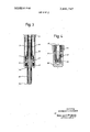
- FIGS. 3 and 4 are sectional elevations of alternative embodiments of the invention relating, respectively, to the embodiments of Figs. 1 and 2 and depicting utilization therein of second shock absorber means.
- a spindle assembly constructed in accordance with the present invention, comprising as its basic elements a spindle shaft 5, a spindle box 6, a resilient tube 1 preferably of plastic material, and a rigid tube 2, each being arranged concentrically relative to the other.
- the spindle shaft 5 is rotatively supported at axially spaced locations proximate its ends by support means which preferably comprise a roller bearing 4 and a ball bearing 7 which peripherally engage the shaft 5, respectively, at the upper and lower ends thereof.
- the roller bearing 4 includes a housing 3 comprising an enlarged diameter section 3a enclosing the roller bearings themselves, and a smaller diameter section 3b which is affixed to the rigid tube 2.
- the ball bearing 7 likewise includes a housing 8 comprising an enlarged diameter section 8b which encloses the ball bearings, and a smaller diameter section 8b affixed to the rigid tube 2 at its opposite end.
- the resilient tube 1 and the rigid tube 2 are affixed together along corresponding upper surfaces designated 1a, 2a.
- the resilient tube 1 is similarly affixed, at an enlarged diameter section 1' thereof, to the spindle box 6 along mating surfaces designated lb, 6b.
- a first shock absorber means preferably comprising a helical spring 9 is interposed between the resilient tube 1 and the spindle box 6.
- the spindle shaft 5 will be completely free to rotate relative to the spindle box 6 while at the same time being resiliently laterally displaceable relative thereto as a result of the cooperation of the elements, particularly the shock absorber means 9 and the resilient tube 1.
- the spindle shaft 5 will maintain a more accurate self centering of its axis of rotation thereby overcoming vibration to effect smoother operation.
- the spindle shaft 5 is formed with an axial bore 10 which adapts the assembly for operation in a two-yarn spinning process.
- the bore 10 comprises a lowersection 10a formed of a larger diameter and an upper section 10b of smaller diameter.
- the secondary yarn of a two-yarn spinning process may be run through the bore 10, and through a guide tube 14 which is mounted to extend to within the larger diameter 10a.
- the guide tube 14 is fitted into a bore 124 drilled through a cover member 12 which is mounted upon the spindle box 6 by threaded engagement with a lower threaded section 11 which engages a mating threaded portion of the cover 12, as indicated in Fig. 1.
- the cover 12 forms an enclosure 13 which serves as an oil reservoir for the assembly, with the guide tube 14 serving to allow passage of a secondary yarn through the axial bore 10 without contact with the oil contained in reservoir 13.
- FIG. 2 depicts a more conventional spindle assembly utilizing, in accordance with the present invention, a mounting arrangement similar to that shown in FIG. 1, with the basic difference between these two embodiments residing in the lower bearing mount for the spindle shaft.
- the assembly of FIG. 2 comprises a spindle shaft 5' having a pointed lower section 16 which engages an end-bearing 15 for axially and rotatively supporting the shaft 5'.
- the bearing 15 is fixedto the lower end of the rigid tube 2, thereby effecting a support similar to that described in connection with FIG. 1 for ball bearing 7, except that the spindle shaft is axially and rotatively supported, instead of being peripherally engaged by the lower bearing means.
- the bearing 15 includes an oil by-pass 17 for circulation of oil which may be contained in a lower enclosure 18 formed integrally with the spindle box 6. It will be apparent that in the arrangement of FIG. 2 the same idle conditions as described in connection with with FIG. 1 will prevail between the spindle shaft and spindle box with the shaft 5' being rotatively resiliently mounted with respect to the box 6 thereby enabling self-centering during operation without transmission of vibration to the box 6.
- FIGS. 3 and 4 depict alternative embodiments of the assemblies of FIGS. 1 and 2, respectively, wherein a second shock absorber means 9' is provided.
- FIG. 3 depicts a ring-shaped shock absorber 9', which should preferably be comprised of a helical spring, as mounted between the cover member 12 and a bushing 19 formed as part 'of the lower ball bearing 7.
- the bushing 19 is threaded over the guide tube 14 and retained fixed relative to the bearing 7 by a support member 8.
- the guide tube 14 be supplemented at its lower end by a ceramic bushing 20, which acts as 'a guide for the secondary yarn, and which is connected to the lower end of cover member 12 by a flexible tube 21.
- FIG. 4 shows the shock absorber 9' interposed between the spindle box 6 and the rigid tube 2 in an embodiment of the type described in connection with FIG. 2 utilizing an end-bearing l5.
- a spindle assembly comprising a spindle shaft, a centering resilient tube, a rigid tube and a spindle box each concentrically located relative to the others with said resilient tube being located between said rigid tube and said spindle box; bearing support means rotatively engaging said spindle shaft at axially spaced locations; first shock absorber means mounted between said spindle box and said resilient tube; means fixedly coupling said resilient tube to said spindle box and to said rigid tube, respectively, at separated axially spaced 'locations; said rigid tube and said spindle box being diametrically dimensioned to provide an annular spacing therebetween enabling flexure of said resilient tube upon lateral relative displacement between said rigid tube and said spindle box; and means fixing said rigid tube to said bearing support means; said spindle shaft being simultaneously freely rotatably supported and resiliently laterally displaceable relative to said spindle box.
Landscapes
- Engineering & Computer Science (AREA)
- Mechanical Engineering (AREA)
- Textile Engineering (AREA)
- Spinning Or Twisting Of Yarns (AREA)
Abstract
A spindle assembly for yarn spinning apparatus provides a resilient rotative idle connection between a spindle shaft and spindle box of the spindle assembly whereby self centering of the axis of rotation of the spindle shaft can occur without transmission of undue vibration to the spindle box during operation. A resilient plastic tube is connected to the spindle box and to a rigid tube which is, in turn, affixed to a pair of bearings mounting the spindle shaft at its ends. First shock absorber means are provided between the resilient tube and the spindle box and in an alternative embodiment of the invention second shock absorber means are provided between the spindle box and the rigid tube at a point longitudinally spaced from said first shock absorber means.
Description
United States Patent Vilanova 1451 Sept. 19,- 1972 'lglfilUgiAlgTURE OF SPINDLES FOR 3,435,604 4/1969 Shotbolt ..57/ 135 X NING AND TWI FRAMES STING FOREIGN PATENTS OR APPLICATIONS 72 Invent Ed d 1,357,733 3/1964 France". ..57/l35 1 "zg g g g xgfggf' 352 1,079,096 8/1967 Great Britain ..5?/135 [22] Filed: Dec. 22, 1970 Primary Examiner-Werner H. Schroeder [2H App 100 567 Attorney-Toren and McGeady II v [57] ABSTRACT Foreign Applicauon Priority Dam A spindle assembly for yarn spinning apparatus pro- Dec. 22, 1969 Spain ..3748l0 des a resilient rotative idle connection between a spindle shaft and spindle box of the spindle assembly 52 us. CI ..57/13s whereby Self centering 9f the axis of "nation of the 511 1111. C1. ..D0lh 7/12 Spindle shaft can occur Without transmission of undue [58] Field of Search ..s7/130, 133,134, 1 I vibration to the spindle box during Operation A 308/150, 151, 1,52 154, 228 resilient plastic tube is connected to the spindle box and to a rigid tube which is, in turn, affixed to a pair [56] References Cited of bearings mounting the spindle shaft at its ends. First shock absorber means are provided between the UNITED STATES PATENTS resilient tube and the spindle box and in an alternative embodiment of the invention second shock absorber s 2 means are provided between the spindle box and the 2863278 12/1958 22; at a 57x35 rigid tube at a point longitudinally spaced from said 3,157,980 11/1964 Kelecom ..5 7 /134 x first absmbe' means 2,650,465 9/1953 Westall ..57/ 6 Claims, 4 Drawing Figures a? El 3 i: i W 2 1 5 52: l 1 i 'i- :F' 55? g5; -T 1'P\ MANUFACTURE OF SPINDLES FOR RING- SPINNING AND TWISTING FRAMES The present invention concerns improvements in the manufacture of spindles for ring-spinning and twisting frames. More particularly, the improvements concern very fast spindles fitted on idle supports, so. as to achieve an accurate centering of swing, through which improvements it is possible to avoid vibration of the spindle supports, and accurate centering of the spindle shaft is achieved, all of which results in a perfectly smooth running.
Essentially, the improvements comprise fitting the spindle shaft so that there is a top and a bottom support for same, this shaft enjoying a certain degree of freedom for radial displacement, by means of a flexible plastic tube connected at its bottom end to the spindle box, and connected at its top end to a ring-shaped shock absorber. This plastic tube is connected in turn, in its inner and top sections, to a rigid tube linked at the top to a roller bearing, and it rests on its bottom on a end-bearing. In this'manner, the spindle shaft is supported at its two opposite ends, to find more easily a center of swing, and no shock absorbers are needed for avoiding vibrations to be transmitted from the spindle to its supports. Further, this idle assembly of the spindle shaft allows for continuously smooth running even if at times the critical speed of the spindle may be surpassed.
Wherever advisable, and more particularly if the spindle shaft is supported on an end-bearing, a ringshaped shock absorber shall be fitted between the rigid tube and the spindle box.
To assist in the description of the invention, two sheets of drawings are enclosed, illustrating two different embodiments of the invention, but without limiting its scope in any way whatever.
In the drawings:
FIG. 1 is a sectional elevational view of a spindle in accordance with the invention which is useful in a twoyam spinning operation and showing the spindle shaft supported by a pair of peripherally engaging bearings;
FIG. 2 is a sectional elevational view of the spindle in accordance with the present invention, fitted with a conventional shaft which is supported at the bottom on an end-bearing.
FIGS. 3 and 4 are sectional elevations of alternative embodiments of the invention relating, respectively, to the embodiments of Figs. 1 and 2 and depicting utilization therein of second shock absorber means.
Referring now in more detail to the drawings, there is shown in Fig. 1 a spindle assembly, constructed in accordance with the present invention, comprising as its basic elements a spindle shaft 5, a spindle box 6, a resilient tube 1 preferably of plastic material, and a rigid tube 2, each being arranged concentrically relative to the other.
The spindle shaft 5 is rotatively supported at axially spaced locations proximate its ends by support means which preferably comprise a roller bearing 4 and a ball bearing 7 which peripherally engage the shaft 5, respectively, at the upper and lower ends thereof.
The roller bearing 4 includes a housing 3 comprising an enlarged diameter section 3a enclosing the roller bearings themselves, and a smaller diameter section 3b which is affixed to the rigid tube 2. The ball bearing 7 likewise includes a housing 8 comprising an enlarged diameter section 8b which encloses the ball bearings, and a smaller diameter section 8b affixed to the rigid tube 2 at its opposite end.
The resilient tube 1 and the rigid tube 2 are affixed together along corresponding upper surfaces designated 1a, 2a. The resilient tube 1 is similarly affixed, at an enlarged diameter section 1' thereof, to the spindle box 6 along mating surfaces designated lb, 6b.
A first shock absorber means, preferably comprising a helical spring 9 is interposed between the resilient tube 1 and the spindle box 6.
In the operation of the spindle assembly depicted in Fig. l, the spindle shaft 5 will be completely free to rotate relative to the spindle box 6 while at the same time being resiliently laterally displaceable relative thereto as a result of the cooperation of the elements, particularly the shock absorber means 9 and the resilient tube 1. Thus, the spindle shaft 5 will maintain a more accurate self centering of its axis of rotation thereby overcoming vibration to effect smoother operation.
In the spindle assembly illustrated in Fig. l, the spindle shaft 5 is formed with an axial bore 10 which adapts the assembly for operation in a two-yarn spinning process. The bore 10 comprises a lowersection 10a formed of a larger diameter and an upper section 10b of smaller diameter. In operation, the secondary yarn of a two-yarn spinning process may be run through the bore 10, and through a guide tube 14 which is mounted to extend to within the larger diameter 10a. The guide tube 14 is fitted into a bore 124 drilled through a cover member 12 which is mounted upon the spindle box 6 by threaded engagement with a lower threaded section 11 which engages a mating threaded portion of the cover 12, as indicated in Fig. 1. The cover 12 forms an enclosure 13 which serves as an oil reservoir for the assembly, with the guide tube 14 serving to allow passage of a secondary yarn through the axial bore 10 without contact with the oil contained in reservoir 13.
FIG. 2 depicts a more conventional spindle assembly utilizing, in accordance with the present invention, a mounting arrangement similar to that shown in FIG. 1, with the basic difference between these two embodiments residing in the lower bearing mount for the spindle shaft. As shown, the assembly of FIG. 2 comprises a spindle shaft 5' having a pointed lower section 16 which engages an end-bearing 15 for axially and rotatively supporting the shaft 5'. The bearing 15 is fixedto the lower end of the rigid tube 2, thereby effecting a support similar to that described in connection with FIG. 1 for ball bearing 7, except that the spindle shaft is axially and rotatively supported, instead of being peripherally engaged by the lower bearing means. The bearing 15 includes an oil by-pass 17 for circulation of oil which may be contained in a lower enclosure 18 formed integrally with the spindle box 6. It will be apparent that in the arrangement of FIG. 2 the same idle conditions as described in connection with with FIG. 1 will prevail between the spindle shaft and spindle box with the shaft 5' being rotatively resiliently mounted with respect to the box 6 thereby enabling self-centering during operation without transmission of vibration to the box 6.
FIGS. 3 and 4 depict alternative embodiments of the assemblies of FIGS. 1 and 2, respectively, wherein a second shock absorber means 9' is provided. FIG. 3 depicts a ring-shaped shock absorber 9', which should preferably be comprised of a helical spring, as mounted between the cover member 12 and a bushing 19 formed as part 'of the lower ball bearing 7. Thus, the shock absorber' 9' is effectively connected between the spindle box 6 and the rigid tube 2. The bushing 19 is threaded over the guide tube 14 and retained fixed relative to the bearing 7 by a support member 8. In this embodiment, it is preferable that the guide tube 14 be supplemented at its lower end by a ceramic bushing 20, which acts as 'a guide for the secondary yarn, and which is connected to the lower end of cover member 12 by a flexible tube 21.
FIG. 4 shows the shock absorber 9' interposed between the spindle box 6 and the rigid tube 2 in an embodiment of the type described in connection with FIG. 2 utilizing an end-bearing l5.
What I claim is:
1. A spindle assembly comprising a spindle shaft, a centering resilient tube, a rigid tube and a spindle box each concentrically located relative to the others with said resilient tube being located between said rigid tube and said spindle box; bearing support means rotatively engaging said spindle shaft at axially spaced locations; first shock absorber means mounted between said spindle box and said resilient tube; means fixedly coupling said resilient tube to said spindle box and to said rigid tube, respectively, at separated axially spaced 'locations; said rigid tube and said spindle box being diametrically dimensioned to provide an annular spacing therebetween enabling flexure of said resilient tube upon lateral relative displacement between said rigid tube and said spindle box; and means fixing said rigid tube to said bearing support means; said spindle shaft being simultaneously freely rotatably supported and resiliently laterally displaceable relative to said spindle box.
2. A spindle assembly according to claim 1, comprising second shock absorber means between said spindle box and said rigid tube.
3. A spindle assembly according to claim 1, wherein said resilient tube is formed of plastic material.
4. A spindle assembly according to claim 1, wherein said first shock absorber means are engaged with said resilient tube at the point at which said resilient tube is coupled to said rigid tube.
5. A spindle assembly according to claim 1, wherein said bearing support means comprises a pair of bearings peripherally engaging said spindle shaft at opposite ends thereof and said spindle shaft includes an axial bore enabling passage of yarn therethrough.
6. A spindle assembly according to claim 1, wherein said bearing support means comprises an end-bearing axially rotatively supporting said spindle shaft at its lower end.
Claims (6)
1. A spindle assembly comprising a spindle shaft, a centering resilient tube, a rigid tube and a spindle box each concentrically located relative to the others with said resilient tube being located between said rigid tube and said spindle box; bearing support means rotatively engaging said spindle shaft at axially spaced locations; first shock absorber means mounted between said spindle box and said resilient tube; means fixedly coupling said resilient tube to said spindle box and to said rigid tube, respectively, at separated axially spaced locations; said rigid tube and said spindle box being diametrically dimensioned to provide an annular spacing therebetween enabling flexure of said resilient tube upon lateral relative displacement between said rigid tube and said spindle box; and means fixing said rigid tube to said bearing support means; said spindle shaft being simultaneously freely rotatably supported and resiliently laterally displaceable relative to said spindle box.
2. A spindle assembly according to claim 1, comprising second shock absorber means between said spindle box and said rigid tube.
3. A spindle assembly according to claim 1, wherein said resilient tube is formed of plastic material.
4. A spindle assembly according to claim 1, wherein said first shock absorber means are engaged with said resilient tube at the point at which said resilient tube is coupled to said rigid tube.
5. A spindle assembly according to claim 1, wherein said bearing support means comprises a pair of bearings peripherally engaging said spindle shaft at opposite ends thereof and said spindle shaft includes an axial bore enabling passage of yarn therethrough.
6. A spindle assembly according to claim 1, wherein said bearing support means comprises an end-bearing axially rotatively supporting said spindle shaft at its lower end.
Applications Claiming Priority (1)
| Application Number | Priority Date | Filing Date | Title |
|---|---|---|---|
| ES37481069 | 1969-12-22 |
Publications (1)
| Publication Number | Publication Date |
|---|---|
| US3691747A true US3691747A (en) | 1972-09-19 |
Family
ID=8454617
Family Applications (1)
| Application Number | Title | Priority Date | Filing Date |
|---|---|---|---|
| US100567A Expired - Lifetime US3691747A (en) | 1969-12-22 | 1970-12-22 | Manufacture of spindles for ring-spinning and twisting frames |
Country Status (3)
| Country | Link |
|---|---|
| US (1) | US3691747A (en) |
| DE (1) | DE2063254A1 (en) |
| FR (1) | FR2074179A5 (en) |
Cited By (2)
| Publication number | Priority date | Publication date | Assignee | Title |
|---|---|---|---|---|
| US3789598A (en) * | 1971-10-26 | 1974-02-05 | Whitin Machine Works | Roving frame bolster |
| US6367237B1 (en) * | 1999-06-29 | 2002-04-09 | Spindelfabrik Neudorf Gmbh | Play-free and centering tube coupling for the spindle of a textile machine |
Families Citing this family (4)
| Publication number | Priority date | Publication date | Assignee | Title |
|---|---|---|---|---|
| CH539697A (en) * | 1972-07-10 | 1973-07-31 | Uster Spindel Motoren Maschf | Textile spindle |
| DD136984B1 (en) * | 1978-06-12 | 1981-06-24 | Friedrich Suess | WAREHOUSE FOR SPIDER AND TWIN SPINDLES |
| FR2664620A1 (en) * | 1990-07-12 | 1992-01-17 | Schlumberger Cie N | Device for mounting the spindles of spinning frames on the spindle rail |
| CH683430A5 (en) * | 1991-07-10 | 1994-03-15 | Rieter Ag Maschf | Spinning or twisting spindle. |
-
1970
- 1970-12-22 US US100567A patent/US3691747A/en not_active Expired - Lifetime
- 1970-12-22 FR FR7046290A patent/FR2074179A5/fr not_active Expired
- 1970-12-22 DE DE19702063254 patent/DE2063254A1/en active Pending
Cited By (2)
| Publication number | Priority date | Publication date | Assignee | Title |
|---|---|---|---|---|
| US3789598A (en) * | 1971-10-26 | 1974-02-05 | Whitin Machine Works | Roving frame bolster |
| US6367237B1 (en) * | 1999-06-29 | 2002-04-09 | Spindelfabrik Neudorf Gmbh | Play-free and centering tube coupling for the spindle of a textile machine |
Also Published As
| Publication number | Publication date |
|---|---|
| FR2074179A5 (en) | 1971-10-01 |
| DE2063254A1 (en) | 1971-06-24 |
Similar Documents
| Publication | Publication Date | Title |
|---|---|---|
| US3691747A (en) | Manufacture of spindles for ring-spinning and twisting frames | |
| US3711168A (en) | Apparatus for mounting a spinning turbine | |
| US2350272A (en) | Spindle | |
| CN208364608U (en) | A kind of motor bearing of low noise | |
| US4457745A (en) | Centrifuge with a belt-driven spindle | |
| EP0010259A1 (en) | A device for supporting a spindle of an open-end spinning frame | |
| US2012579A (en) | High speed vertical shaft type motor | |
| GB1202071A (en) | Spindle assembly for a spinning or twisting machine | |
| US2981051A (en) | Spindle bearing arrangement | |
| US4997291A (en) | Bearing for spindles of spinning or twisting machines | |
| GB1425718A (en) | Bearing for spinning and twisting spindles | |
| US2576124A (en) | Double twist spindle | |
| CN108048969B (en) | Electric ingot with annular elastic supporting component and electric ingot suspension structure | |
| CN207468800U (en) | The straight hole centering swelling device that motor is connect with spindle blade in a kind of electricity ingot | |
| US2750237A (en) | Bearing means for spinning and doubling spindles | |
| US3421306A (en) | Roving frame | |
| US3546871A (en) | Damped support for double twist spindle | |
| US2909027A (en) | Textile spindle | |
| US3157980A (en) | Hollow textile spindle | |
| CN205662647U (en) | Chemical fibre two -for -one twisting spindles | |
| GB1392158A (en) | Textile spindle | |
| US2210358A (en) | Twisting spindle, especially for artificial silk | |
| US5775083A (en) | Spindle for a spinning or a twisting machine | |
| JP6180278B2 (en) | Base bearing unit of spindle bearing device, spindle bearing device and textile machine | |
| SU117880A1 (en) | Spindle for twisting machines |