US3684263A - Vacuum oil quench furnace - Google Patents
Vacuum oil quench furnace Download PDFInfo
- Publication number
- US3684263A US3684263A US10923A US3684263DA US3684263A US 3684263 A US3684263 A US 3684263A US 10923 A US10923 A US 10923A US 3684263D A US3684263D A US 3684263DA US 3684263 A US3684263 A US 3684263A
- Authority
- US
- United States
- Prior art keywords
- load
- furnace
- quenching
- chamber
- transfer mechanism
- Prior art date
- Legal status (The legal status is an assumption and is not a legal conclusion. Google has not performed a legal analysis and makes no representation as to the accuracy of the status listed.)
- Expired - Lifetime
Links
Images


Classifications
-
- C—CHEMISTRY; METALLURGY
- C21—METALLURGY OF IRON
- C21D—MODIFYING THE PHYSICAL STRUCTURE OF FERROUS METALS; GENERAL DEVICES FOR HEAT TREATMENT OF FERROUS OR NON-FERROUS METALS OR ALLOYS; MAKING METAL MALLEABLE, e.g. BY DECARBURISATION OR TEMPERING
- C21D1/00—General methods or devices for heat treatment, e.g. annealing, hardening, quenching or tempering
- C21D1/74—Methods of treatment in inert gas, controlled atmosphere, vacuum or pulverulent material
- C21D1/773—Methods of treatment in inert gas, controlled atmosphere, vacuum or pulverulent material under reduced pressure or vacuum
-
- C—CHEMISTRY; METALLURGY
- C21—METALLURGY OF IRON
- C21D—MODIFYING THE PHYSICAL STRUCTURE OF FERROUS METALS; GENERAL DEVICES FOR HEAT TREATMENT OF FERROUS OR NON-FERROUS METALS OR ALLOYS; MAKING METAL MALLEABLE, e.g. BY DECARBURISATION OR TEMPERING
- C21D1/00—General methods or devices for heat treatment, e.g. annealing, hardening, quenching or tempering
- C21D1/62—Quenching devices
- C21D1/63—Quenching devices for bath quenching
- C21D1/64—Quenching devices for bath quenching with circulating liquids
Definitions
- a vacuum quenching apparatus comprises a vacuum chamber in which is mounted a heating furnace and a quenching tank.
- a dolly rides on rails from a position over the quenching tank to a position adjacent the furnace and is provided with parallel supporting arms which support a load therebetween and which extend into the furnace when the dolly is positioned adjacent thereto.
- the arms are counter-rotatable so as to release a load and permit the load to descend vertically downwardly either within the furnace or upon a hydraulic cylinder mounted within the quench tank.
- An end of the chamber is also displaceable, and the dolly moves outwardly with the displaceable end to permit loading or unloading.
- the apparatus for carrying out such a heat-treating quench process generally comprises a heating furnace and an oil-filled quench tank.
- the quench tank is usually kept as cool as possible and is therefore separated from the heating furnace by a heat shield or even by a vacuum door.
- the resulting structure is unduly complicated and requires considerable skill in operation in order to carry out properly aquenching process.
- One of the objects of the present invention is to provide an improved integral vacuum quenching apparatus.
- Another of the objects of the present invention is to provide an improved transfer mechanism for a vacuum quenching apparatus.
- Another of the objects of the present invention is to facilitate the transfer of the load in and out of the heating furnace of a vacuum chamber and positioning the load over the quenching oil for immersion therein.
- a vacuum quenching apparatus may be provided with a chamber which is evacuable to a sub-atmospheric pressure, the chamber having a heating furnace therein.
- a quenching tank is also positioned within the vacuum chamber and mounted lower than the heating furnace.
- a transfer mechanism is movable into and out of the furnace to a position over the quenching tank.
- the transfer mechanism includes means for supporting a load and for releasing the load vertically downwardly.
- hydraulic cylinder means Within the quenching tank are provided hydraulic cylinder means to receive a load released from the transfer mechanism when the transfer mechanism is positioned over the quenching tank.
- the transfer mechanism may comprise rail means within the chamber extending over the quenching tank and underneath the furnace with there being a dolly movably mounted on the rail means.
- the dolly may comprise a pair of parallel supporting arms which extend into the furnace when the dolly is moved on the rail means underneath the furnace.
- the arms have inwardly directed ledges upon which the load is actually supported, and the arms may be counter-rotated so that the ledges are pivoted from under a load to permit the load to be released vertically downwardly.
- FIG. 1 is a vertical longitudinal sectional view of a vacuum quenching apparatus according to the present invention
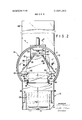
- FIG. 2 is a sectional view taken along the line 22 of FIG. 1;
- FIG. 3 is a sectional view taken along the line 3-3 of FIG. 1;
- FIG. 4 is a portion of a view similar to that of FIG. I but showing an end plate of the chamber in an open position;
- FIG. 5 is a top plan view of the apparatus as shown in FIG. 4.
- the vacuum quenching apparatus of the present invention comprises a chamber means indicated generally at 10 which can be evacuated to establish a vacuum therein.
- the chamber comprises a horizontally disposed cylinder 11 surrounded by a water jacket 12 and having a fixed end 13 and a removable end 14.
- a cylindrical quenching tank 15 is connected to the lowermost portion of the cylinder 11 to communicate therewith.
- the heating furnace 16 which may be electric, is positioned within the cylindrical portion 11 adjacent the fixed end 13.
- the furnace 16 is provided with a door 17 which is lifted outwardly and upwardly by a hydraulic piston arrangement 18 mounted within an enclosure 19 projecting above the upper surface of the cylinder. Suitable linkage 20 connects the door to the hydraulic piston.
- a plurality of vertical supporting members 21 upon which a load is to be positioned.
- the quenching tank 15 is provided with watercooled cylindrical walls 22 and 23 to dissipate the heat between quenches. Openings 24 are provided under the bottom of the wall 22. These cylindrical walls provide a channeling effect to the quench oil so that percent of the flow is flushed through the work.
- the quenching oil is circulated in the directions indicated by the arrows by a motor-driven agitator 26.
- Hydraulic cylinder 27 Mounted within the innermost wall 22 in the quenching tank 15 is a hydraulic cylinder 27 of the single-acting ram type which is totally submerged in the quenching oil and which may be raised out of the oil to receive or deposit the load.
- the hydraulic cylinder 27 may be of the telescoping type in order not to occupy excessive space within the quenching tank.
- the upper end of hydraulic cylinder 27 is provided with a supporting platform 27A upon which a load 28 may be positioned. Hydraulic cylinder 27 may be operated with the same oil as used for quenching or with oil emulsions of the nature used for quenching so that any leaks from the cylinder would not contaminate the quench bath.
- the mechanism for transferring a load, such as indicated at 28, from the furnace 16 to the quenching tank 15 comprises a dolly 29 mounted on wheels 30 upon a pair of parallel rails 31 which extend over the quenching tank 15 and underneath the furnace 16 as shown in FIG. 1.
- the rails are broken at 31A so that the left portion can be moved with end 14 when the end is opening as can be seen in FIG. 4.
- a vertical supporting upright 32 from which extend two spaced parallel supporting arms 33 which, as may be seen in FIG. 2, are spaced apart a distance slightly greater than the width of the load 28.
- the supporting arms are rotatably mounted in bearing blocks 34 and on their inner faces are provided with inwardly extending ledges 35 upon which the load 28 actually rests as shown in FIG. 2.
- a lever arm 36 extends outwardly from each of the supporting arms 33 and is pivotally connected at 37 to a piston rod 38 of a hydraulic cylinder 39 having its upper end connected at 40 on the upright structure 32. Actuation of the hydraulic cylinder 39 to retract piston rod 38 will rotate the supporting arm 33 approximately 90 and cause the supporting ledges 35 to be pivoted to the dashed line position indicated at 35A.
- Dolly 29 moves horizontally upon the rails 31 by means of an endless chain 41 to which it is connected.
- Chain 41 will pull the dolly in either direction upon its wheels.
- This chain 41 is driven by suitable shaftmounted sprocket gears.
- the removable end 14 of the cylinder is mounted by means of a suitable supporting structure indicated at 42 to wheels 43 which roll upon parallel rails 44 secured to the outer surface of the cylinder 11 as may be seen in FIGS. 4 and 5.
- the removable end 14 may be displaced to the position as shown in FIGS. 4 and together with the dolly 29 to provide access to the dolly and facilitate the loading and unloading thereof.
- the vacuum pump is started to begin evacuation of the chamber to the desired vacuum or pressure and the several hydraulic pump motors also are started.
- a load 28 is placed upon the dolly.
- Removable cylinder end 14 is then closed to move the work load 28 into the cooling section as shown in FIG. 1.
- evacuation of the chamber begins.
- the furnace door 17 is opened and the work load 28 introduced into the furnace by moving the dolly into a position underneath the furnace.
- the supporting arms will protrude into the chamber and are rotated to permit the work load to be positioned upon the supports 21 within the furnace.
- the quench oil agitator Upon completion of the heat cycle, the quench oil agitator is started. When the correct oil temperature is attained, the door of the heating furnace is opened and the work removed therefrom by the transfer mechanism. When the work is loaded on the supporting arms, the dolly is moved rearwardly to the position as shown in FIG. 1, and the hydraulic quench cylinder 27 is actuated so that its support platform 27A is in position to receive the work load 28. The supporting arms of the dolly are again counter-rotated to release the load upon the support platform. The cylinder will then lower the work into the oil quench bath.
- the quench cylinder Upon completion of the quenching cycle, the quench cylinder will raise the work onto the transfer mechanism and then air is admitted into the chamber and the removable end 14 is opened to withdraw the work from the chamber.
- the apparatus may also be used for a gas quenching process.
- the vacuum valve is closed, and a back-fill valve is opened to admit a suitable gas into the chamber.
- a circulating fan 45 located within the chamber is driven by electric motor 46 to circulate the gas throughout the chamber.
- a vacuum oil quenching apparatus employing a transfer mechanism according to the present invention has several advantages.
- the work load supports in the heating chamber may be constructed in a manner of simple stationary pier supports without the necessity for providing any lifting, lowering or sidewise motions with respect to the transfer of work into and out of the heating furnace.
- the transfer of the work load to and from the transfer mechanism does not depend on any sliding, skidding, rolling or other movements causing friction which would be detrimental in a high temperature environment. Further, the dolly remains over the oil quenching tank to transfer and receive the load from the quenching elevator.
- chamber means evacuable to sub-atmospheric pressure, a heating furnace within said chamber means, a quenching tank within said chamber means and lower than said heating furnace, a horizontally movable transfer mechanism movable into and out of said furnace and to a position over said quenching tank, means mounted on said horizontally movable transfer mechanism for supporting a load and operable for releasing a load supported thereon vertically downwardly, and vertically movable transfer means within said quenching tank movable upwardly to receive a load when released from said transfer mechanism when the transfer mechanism is in position over the quenching tank and .moving the load downwardly without the horizontally movable transfer means and into the quenching tank and for moving it upwardly after quenching where it can again be transferred onto said horizontally movable transfer mechanism.
- chamber means mospheric pressure, a heating furnace within said chamber means, a quenching tank within said chamber means and lower than said heating furnace, a horizontally movable transfer mechanism movable into and out of said furnace and to a position over said quenching tank, means on said horizontally movable transfer mechanism for supporting a load and for releasing a load vertically downwardly, said transfer mechanism including rail means within said chamber extending over said quenching tank and underneath said furnace, and a dolly movably mounted on said rail means, and vertically movable transfer means within said quenching tank movable upwardly to receive a load when released from said transfer mechanism when the transfer mechanism is in position over the quenching tank and moving the load downwardly into the quenching tank and for moving it upwardly after quenching.
- said dolly comprises a pair of parallel supporting arms positioned to extend into said furnace when the dolly is moved on said rail means underneath the furnace.
Landscapes
- Chemical & Material Sciences (AREA)
- Engineering & Computer Science (AREA)
- Physics & Mathematics (AREA)
- Thermal Sciences (AREA)
- Crystallography & Structural Chemistry (AREA)
- Mechanical Engineering (AREA)
- Materials Engineering (AREA)
- Metallurgy (AREA)
- Organic Chemistry (AREA)
- Heat Treatment Of Articles (AREA)
- Tunnel Furnaces (AREA)
Applications Claiming Priority (1)
| Application Number | Priority Date | Filing Date | Title |
|---|---|---|---|
| US1092370A | 1970-02-12 | 1970-02-12 |
Publications (1)
| Publication Number | Publication Date |
|---|---|
| US3684263A true US3684263A (en) | 1972-08-15 |
Family
ID=21748048
Family Applications (1)
| Application Number | Title | Priority Date | Filing Date |
|---|---|---|---|
| US10923A Expired - Lifetime US3684263A (en) | 1970-02-12 | 1970-02-12 | Vacuum oil quench furnace |
Country Status (6)
| Country | Link |
|---|---|
| US (1) | US3684263A (enExample) |
| CA (1) | CA929349A (enExample) |
| DE (1) | DE2018862A1 (enExample) |
| ES (1) | ES380160A1 (enExample) |
| FR (1) | FR2058001A5 (enExample) |
| GB (1) | GB1313409A (enExample) |
Cited By (15)
| Publication number | Priority date | Publication date | Assignee | Title |
|---|---|---|---|---|
| US3830479A (en) * | 1972-08-23 | 1974-08-20 | M Knowles | Heat treatment furnace |
| US4487398A (en) * | 1981-09-21 | 1984-12-11 | Atmosphere Furnace Company | Salt bath quenching apparatus |
| US5008867A (en) * | 1990-07-23 | 1991-04-16 | Ko Wei C | Ornamental clock with decorative time indicating device |
| US5106059A (en) * | 1990-04-02 | 1992-04-21 | Federal-Mogul Corporation | Siphon driven quench tank assembly |
| US5447293A (en) * | 1994-07-22 | 1995-09-05 | Clarke; Beresford N. | Method and apparatus for quenching heat treated objects |
| US5492168A (en) * | 1994-07-18 | 1996-02-20 | Indugas, Inc. | High convective heat transfer immersion heater/cooler |
| US5795538A (en) * | 1993-01-27 | 1998-08-18 | Dowa Mining Co., Ltd. | Apparatus for steel hardening and process therefor |
| US20100143080A1 (en) * | 2008-01-14 | 2010-06-10 | Loi Thermprocess Gmbh | Device and method for loading and unloading a heat treatment furnace |
| CN102002565A (zh) * | 2010-12-20 | 2011-04-06 | 浙江省青田超达铸造有限公司 | 一种热处理快速冷却装置 |
| US20110284132A1 (en) * | 2010-05-20 | 2011-11-24 | Hightemp Furnaces Limited | Method for reduction of time in a gas carburizing process and cooling apparatus |
| CN103954141A (zh) * | 2014-04-15 | 2014-07-30 | 苏州工业园区热处理设备厂有限公司 | 淬火炉排烟罩 |
| EP2980229A1 (en) * | 2014-07-29 | 2016-02-03 | ELTI S.r.l. | Apparatus for thermal treatments of metals, particularly for hardening and tempering steel |
| CN106319171A (zh) * | 2016-11-08 | 2017-01-11 | 天津昭阳科技有限公司 | 一种锻压液态铝轮毂冷却提升系统 |
| CN108728619A (zh) * | 2018-09-07 | 2018-11-02 | 江苏正和实业集团有限公司 | 一种铝管淬火装置 |
| CN109517950A (zh) * | 2019-01-09 | 2019-03-26 | 滦南县丰田五金农具制造有限公司 | 一种可调连续式五金工具压沾、淬火、冷却一体机及工艺 |
Families Citing this family (6)
| Publication number | Priority date | Publication date | Assignee | Title |
|---|---|---|---|---|
| FR2426877A1 (fr) * | 1978-05-23 | 1979-12-21 | Physique Appliquee Ind | Perfectionnements apportes aux fours a vide a dispositif incorpore de trempe en lit fluidise |
| EP0747493A3 (fr) * | 1995-06-07 | 1996-12-18 | Patherm SA | Installation de traitement thermique |
| DE102004060354B4 (de) * | 2004-12-15 | 2008-08-21 | Elti S.R.L. | Anlage für Wärmebehandlungen von Metallen, insbesondere für das Härten und das Vergüten von Stahl |
| CN104178609B (zh) * | 2013-05-22 | 2016-06-08 | 东莞市禾盛金属科技有限公司 | 一种真空炉 |
| JP6296657B2 (ja) * | 2014-06-26 | 2018-03-20 | 株式会社Ihi | 熱処理装置 |
| CN112760466B (zh) * | 2021-01-22 | 2024-11-01 | 苏州思赛力热能发展有限公司 | 一种金属热成型用淬火炉 |
Citations (5)
| Publication number | Priority date | Publication date | Assignee | Title |
|---|---|---|---|---|
| US1888960A (en) * | 1932-05-13 | 1932-11-22 | George J Hagan Company | Continuous hardening, quenching, and drawing furnace |
| US2458084A (en) * | 1941-12-09 | 1949-01-04 | Lee Jess Max | Heat-treating system |
| FR987910A (fr) * | 1943-02-17 | 1951-08-21 | Brevets Aero Mecaniques Soc D | Perfectionnements apportés aux coussinets en bronze au plomb, notamment à ceux comportant une carcasse en acier, et aux moyens pour leur établissement |
| US3025044A (en) * | 1958-01-30 | 1962-03-13 | Sunbeam Equip | Vacuum furnace |
| US3441452A (en) * | 1964-12-31 | 1969-04-29 | Hayes Inc C I | High vacuum electric furnace |
-
1970
- 1970-02-12 US US10923A patent/US3684263A/en not_active Expired - Lifetime
- 1970-04-14 DE DE19702018862 patent/DE2018862A1/de active Pending
- 1970-05-29 ES ES380160A patent/ES380160A1/es not_active Expired
- 1970-06-15 GB GB2889570A patent/GB1313409A/en not_active Expired
- 1970-06-23 CA CA086288A patent/CA929349A/en not_active Expired
- 1970-08-12 FR FR7029753A patent/FR2058001A5/fr not_active Expired
Patent Citations (5)
| Publication number | Priority date | Publication date | Assignee | Title |
|---|---|---|---|---|
| US1888960A (en) * | 1932-05-13 | 1932-11-22 | George J Hagan Company | Continuous hardening, quenching, and drawing furnace |
| US2458084A (en) * | 1941-12-09 | 1949-01-04 | Lee Jess Max | Heat-treating system |
| FR987910A (fr) * | 1943-02-17 | 1951-08-21 | Brevets Aero Mecaniques Soc D | Perfectionnements apportés aux coussinets en bronze au plomb, notamment à ceux comportant une carcasse en acier, et aux moyens pour leur établissement |
| US3025044A (en) * | 1958-01-30 | 1962-03-13 | Sunbeam Equip | Vacuum furnace |
| US3441452A (en) * | 1964-12-31 | 1969-04-29 | Hayes Inc C I | High vacuum electric furnace |
Cited By (17)
| Publication number | Priority date | Publication date | Assignee | Title |
|---|---|---|---|---|
| US3830479A (en) * | 1972-08-23 | 1974-08-20 | M Knowles | Heat treatment furnace |
| US4487398A (en) * | 1981-09-21 | 1984-12-11 | Atmosphere Furnace Company | Salt bath quenching apparatus |
| US5106059A (en) * | 1990-04-02 | 1992-04-21 | Federal-Mogul Corporation | Siphon driven quench tank assembly |
| US5008867A (en) * | 1990-07-23 | 1991-04-16 | Ko Wei C | Ornamental clock with decorative time indicating device |
| US5795538A (en) * | 1993-01-27 | 1998-08-18 | Dowa Mining Co., Ltd. | Apparatus for steel hardening and process therefor |
| US5492168A (en) * | 1994-07-18 | 1996-02-20 | Indugas, Inc. | High convective heat transfer immersion heater/cooler |
| US5447293A (en) * | 1994-07-22 | 1995-09-05 | Clarke; Beresford N. | Method and apparatus for quenching heat treated objects |
| US8298474B2 (en) * | 2008-01-14 | 2012-10-30 | Loi Thermprocess Gmbh | Device and method for loading and unloading a heat treatment furnace |
| US20100143080A1 (en) * | 2008-01-14 | 2010-06-10 | Loi Thermprocess Gmbh | Device and method for loading and unloading a heat treatment furnace |
| US20110284132A1 (en) * | 2010-05-20 | 2011-11-24 | Hightemp Furnaces Limited | Method for reduction of time in a gas carburizing process and cooling apparatus |
| CN102002565A (zh) * | 2010-12-20 | 2011-04-06 | 浙江省青田超达铸造有限公司 | 一种热处理快速冷却装置 |
| CN103954141A (zh) * | 2014-04-15 | 2014-07-30 | 苏州工业园区热处理设备厂有限公司 | 淬火炉排烟罩 |
| EP2980229A1 (en) * | 2014-07-29 | 2016-02-03 | ELTI S.r.l. | Apparatus for thermal treatments of metals, particularly for hardening and tempering steel |
| CN106319171A (zh) * | 2016-11-08 | 2017-01-11 | 天津昭阳科技有限公司 | 一种锻压液态铝轮毂冷却提升系统 |
| CN108728619A (zh) * | 2018-09-07 | 2018-11-02 | 江苏正和实业集团有限公司 | 一种铝管淬火装置 |
| CN109517950A (zh) * | 2019-01-09 | 2019-03-26 | 滦南县丰田五金农具制造有限公司 | 一种可调连续式五金工具压沾、淬火、冷却一体机及工艺 |
| CN109517950B (zh) * | 2019-01-09 | 2023-04-25 | 滦南县丰田五金农具制造有限公司 | 一种可调连续式五金工具压淬、淬火、冷却一体机及工艺 |
Also Published As
| Publication number | Publication date |
|---|---|
| DE2018862A1 (de) | 1971-09-02 |
| CA929349A (en) | 1973-07-03 |
| ES380160A1 (es) | 1972-08-16 |
| GB1313409A (en) | 1973-04-11 |
| FR2058001A5 (enExample) | 1971-05-21 |
Similar Documents
| Publication | Publication Date | Title |
|---|---|---|
| US3684263A (en) | Vacuum oil quench furnace | |
| JP4645592B2 (ja) | 2室型熱処理炉 | |
| EP1319724B1 (en) | Vacuum heat-treatment apparatus | |
| JP4428268B2 (ja) | 熱処理炉 | |
| CN101018997A (zh) | 真空热处理炉的冷却气体风路切换装置 | |
| JP2005016861A (ja) | 真空熱処理炉の冷却ガス風路切替え装置 | |
| JP6479141B1 (ja) | ワークの焼入処理装置 | |
| US3659831A (en) | Integral quench furnace and transfer mechanism | |
| JP4420332B2 (ja) | 鋼の油焼入方法及び装置 | |
| US5265851A (en) | Installation for the heat treatment of successive batches | |
| US4709904A (en) | Vacuum furnace for heat-treating a charge | |
| JP5571291B2 (ja) | 熱処理装置 | |
| US3633895A (en) | Vacuum water dump quench | |
| US5567381A (en) | Hybrid heat treating furnace | |
| US3522357A (en) | Vacuum furnace having a liquid quench and a vertically movable work holder | |
| US3866891A (en) | Vacuum furnace equipment for heat treatment, hardening and brazing working parts | |
| US4086050A (en) | Method and apparatus for gas circulation in a heat treating furnace | |
| US3718324A (en) | Vacuum furnace and work cart for use therein | |
| US3381947A (en) | Furnace vestibule having a movable ceiling | |
| JPS5855526A (ja) | 雰囲気熱処理装置 | |
| US2023101A (en) | Furnace | |
| JPS6123000Y2 (enExample) | ||
| CA1236293A (en) | Workpiece charger for heating furnace | |
| US2265849A (en) | Heat treating apparatus | |
| CN111850282A (zh) | 一种水平筒形炉 |