US3673972A - Sewing machine with combined accessory receptacle and auxiliary bed - Google Patents
Sewing machine with combined accessory receptacle and auxiliary bed Download PDFInfo
- Publication number
- US3673972A US3673972A US55434A US3673972DA US3673972A US 3673972 A US3673972 A US 3673972A US 55434 A US55434 A US 55434A US 3673972D A US3673972D A US 3673972DA US 3673972 A US3673972 A US 3673972A
- Authority
- US
- United States
- Prior art keywords
- receptacle
- bed
- recess
- extension
- machine
- Prior art date
- Legal status (The legal status is an assumption and is not a legal conclusion. Google has not performed a legal analysis and makes no representation as to the accuracy of the status listed.)
- Expired - Lifetime
Links
- 238000009958 sewing Methods 0.000 title claims abstract description 11
- 230000000295 complement effect Effects 0.000 description 3
- 210000005069 ears Anatomy 0.000 description 1
- 230000000694 effects Effects 0.000 description 1
Images


Classifications
-
- D—TEXTILES; PAPER
- D05—SEWING; EMBROIDERING; TUFTING
- D05B—SEWING
- D05B77/00—Covers, or portable enclosures, for sewing machines
Definitions
- One of the objects of this invention is the provision of an accessory receptacle housed within the base of the machine and arranged to be positioned so as to extend the work surface area of the bed of the machine.
- Another object of this invention is the provision of an accessory receptacle of the foregoing character affording ready access to the interior of the receptacle for the placement or removal of accessories or attachments.
- Still another object of this invention is the provision of an accessory receptacle in the base of the machine which is readily detachable from the machine.
- a further object of this invention is the provision of an accessory receptacle disposed in the base of the machine and so arranged that it does not impair either the function or the appearance of the machine.
- FIG. l is aperspective view of a sewing machine illustrating a preferred embodiment of my invention and showing the same with the receptacle in extended condition.
- FIG. 2 is a transverse cross-sectional view, on an enlarged scale, of the bed of the machine taken on line 22 of FIG. 1, and showing the receptacle in extended position.
- FIG. 3 is a view similar to that of FIG. 2 showing the receptacle in normal retracted position.
- FIG. 4 is a fragmentary cross-sectional view, on an enlarged scale, illustrating a structural detail in extended position.
- FIG. 5 is a view similar to FIG. 3 illustrating a modified embodiment of my invention.
- FIG. 6 is a fragmentary perspective view of a structural detail of the embodiment illustrated in FIG. 5.
- FIG. 7 is a perspective view of another modified embodiment of my invention and showing the receptacle in extended position.
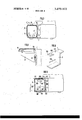
- FIG. 8 is a transverse cross-sectional view, on an enlarged scale, of the embodiment illustrated in FIG. 7 and showing the receptacle in normal retracted position.
- FIG. 9 is a fragmentary perspective view of an end wall defining the recess in the bed of the embodiment illustrated in FIGS. 1-4.
- FIG. 10 is a similar view of an end wall of the receptacle illustrated in FIGS. l3.
- the numeral 1 indicates the bed of a portable sewing machine provided with a recess or space 2 extending longitudinally of the forward portion of bed 1.
- a receptacle A is adapted to be removably received in the space 2.
- Said receptacle comprises a bottom 3, front and back walls 4 and 5, respectively, side walls 6, 6 and a cover 7.
- the cover 7 is provided with a pair of depending ears 10 each carrying an outwardly extending pin 11 arranged to be received in a corresponding recess in each of the walls 6,6.
- the pins 1 l are coaxially aligned and the cover 7 is adapted to be rocked about the axis of pins 11.
- Each of the walls 6, 6 is provided with an outwardly extending stud 8, the studs 8 being coaxial.
- Each of the walls 6, 6 is further provided on its outer surface with an integrally formed elongated projection 9 substantially parallel to the rear wall 5, and projections being in alignment with each other.
- the space 2 in the base of the machine is defined by spaced parallel end walls 12, each provided on its inner surface with a boss 13 shaped substantially as illustrated by the broken line in FIGS. 2 and 3.
- the bosses 13 are in alignment and each includes a bearing portion 14 opening upwardly and adapted to receive a respective stud 8 to rockably support the receptacle A
- the cover 7 is provided with an offset extension 7 rearwardly of the pivotal axis 1 l, as viewed in FIG. 2.
- a cover member 15 is pivotally supported between the walls 12 by pins 16.
- This cover members 15 has a beveled longitudinal edge which cooperates with complementary surfaces of the receptacle A, as will be hereinafter explained, to provide a flush continuous surface constituting the work surface area of the bed.
- the receptacle A is shown in normal retracted position within the chamber 2 and in such position the wall 5 is in engagement with the bottom wall of the base of the machine. correspondingly, the cover member 15 is rested on the wall 4 with the longitudinal beveled edge thereof in engagement with a complementary inclined surface of the longitudinally extending thickened portion 4'. As will be seen clearly in FIG. 3, in such condition the cover 15 is flush with the surface of bed 1.
- the cover 15 is provided on its underside with a depending lug 17 which normally occupies a space immediately below the pivotal axis, at the right hand of the cover member 15, as viewed in FIG. 1.
- a depending lug 17 which normally occupies a space immediately below the pivotal axis, at the right hand of the cover member 15, as viewed in FIG. 1.
- the cover 7 of the receptacle functions as an extension of the bed 1 of the machine substantially increasing the available work surface area of the machine.
- the cover 7 may be rocked to open position to afford access to the interior of the receptacle for the removal of attachments, accessories or other items contained within the receptacle.
- the receptacle A is held securely in position to support any weight applied on the work surface area of the cover 7. It will also be understood that the receptacle may be removed in its entirety from the bed of the machine merely by lifting the receptacle in an upwardly direction so that the pins 8 clear the bearings 14.
- the cover 15 In order to retract the receptacle A within the space 2 the cover 15 is again rocked to open position in a clockwise direction and the receptacle A is rocked in a similar direction to a point where the projections 9 on the walls 6 of the receptacle engage the shoulders 12' of the bosses 13 on the walls 12. correspondingly, the wall 5 is in engagement with the bottom of the bed and the receptacle is now in a stable position so that the cover 15 may be rocked counter-clockwise to closed position like that illustrated in FIG. 3.
- An auxiliary bed extension 18 substantially coextensive in area with the right end wall 12 of the bed (FIG. 1) is pivotally supported on pins 20 carried by brackets attached to the wall 12.
- a supporting bracket 22 is hinged to the right end wall 12 on a vertical axis and is biased by a spring 21 to swing away from the wall 12 when freed by the upper movement of extension 18. Movement of the bracket 22 to a position 90 away from wall 12 is limited by an abutment 23 carried on the underside of the extension 18.
- bracket 22 In order to lower the extension 18 to normal non-functioning position the bracket 22 is swung to a position contiguous to the wall 12 thus, permitting the extension 18 to drop to a vertical position, as illustrated in FIG. 1. In this position the spring biased bracket 22 is held in non-operative position by the vertically disposed extension 18.
- the accessory receptacle B comprises a bottom wall 101, front wall 102, back wall 103, end walls 104 and a cover plate 105.
- the cover plate is hingedly connected by pins 106 to the end walls 104 and may be rocked about the axis of said pins to open and closed positions.
- Each of the end walls 104 is provided with a stud 107 extending outwardly and arranged to be received in a respective L-shaped recess 109 formed in the end walls 116 defining the space 2 in the bed of the machine. As seen clearly in FIG.
- each of the end walls 116 is provided on its inner surface with a lateral elongated projection 110 extending in horizontal direction and disposed below the recess 109.
- each end wall 104 of the receptacle B is provided with a similar projection 108 so disposed in relation to the projection 110 that when the pins 107 are received in the horizontal legs of the L-shaped slots 109 the projections 108 will rest on projections 110.
- a cover 111 is hingedly connected to the bed 1 by pins 112 which extend into apertures 115 provided in the end walls 1 16 of the bed.
- the cover 105 is provided on its surface with a recess to accommodate the cover 111 so that in close position it is flush with the work surface area of the bed.
- the receptacle B in the solid line position is retracted within the space 2 and in this position the pins 107 are disposed at the extreme right of each horizontal leg of recesses 109. Also, the left hand edge of the cover 111 is in abutment with a shoulder 113 in cover 105. In this position receptacle B is held securely against horizontal sliding movement in either direction and the work surface of the bed is substantially flush. In order to obtain access to the interior of receptacle B, it is slidably moved outwardly to the dotted line position where the pins 107 engage the left hand ends of the horizontal legs of recesses 109 and both covers 105 and 111 are rocked upwardly.
- receptacle B is permitted to remain in the dotted line position and upon closing of the covers 105 and 111 the free end of the cover 111 will engage against a shoulder 114 provided in the cover 105 thereby locking the receptacle against movement in either direction. In this position the work surface area of the bed also is substantially flat.
- the arrangement is substantially similar to that illustrated in FIGS. 5 and 6 except that hinged cover 111 of the embodiment illustrated in FIG. 5 is replaced by an integral extension 206 of the bed plate of the machine.
- the receptacle C comprises a bottom wall 201, a front wall 202, a rear wall 203, end walls 204 and a hinged cover plate 205.
- the end walls of the bed space 2 are provided with L-shaped recesses 209 in which are received the laterally projecting pins 207 carried on the end walls 204 of the receptacle C.
- the end walls of the bed space 2 have horizontal projections 210 which are engaged by corresponding projections 208 integral with the walls 204.
- the receptacle C is in retracted position and occupies the space 2 in the bed of the machine and in this position the pins 207 are disposed at the extreme right ends of the horizontal legs of the recesses 209.
- the extension 206 of the bed plate which overhangs the receptacle C has a lesser thickness than the balance of the bed surface plate so as to the height of the step between the surface of the cover 205 and that of bed plate 206.
- the receptacle C may be drawn outwardly to the position illustrated by the broken lines in FIG. 8 and the solid lines in FIG. 7 to permit cover 205 to be opened to afford access to the interior of the receptacle. Additionally, in such outward position the cover 205 functions as an extension of the machine bed 1.
- each of the embodiments may include the end structure illustrated in FIG. 4.
- the receptacle is housed in the space provided in the bed of the sewing machine and may be selectively drawn outwardly thereof, either for the purpose of affording access to the interior of the receptacle or to function as an extension of the bed of the machine and in each case the receptacle in its entirely may be removed from the machine bed.
- a sewing machine having a bed having a work surface and a longitudinally extending recess in the forward portion of the bed, said recess being defined by two end walls, a bottom wall and a rear wall and being open at the top and front, each of the side walls having associated bearing portions, a receptacle adapted to contain machine accessories and being received in said recess, said receptacle having end walls having outwardly extending co-axially aligned studs received in said bearing portions, said receptacle being rockable about the axis of said studs from a retracted position wherein the receptacle is substantially fully contained within said recess to an extended position wherein the major portion of the receptacle is disposed outwardly of the recess.
- stop means for limiting the movement of said receptacle in retracted and extended positions.
- the invention as defined in claim 1 including a cover panel hingedly connected to the rear wall of said recess and arranged to overlie said receptacle and to be disposed in coplanar relationship with the work surface when the receptacle is in closed position.
- the invention as defined in claim 1 including a hinged cover on said receptacle, said hinged cover being disposed adjacent and parallel to said rear wall when the receptacle is in retracted position.
Landscapes
- Engineering & Computer Science (AREA)
- Textile Engineering (AREA)
- Sewing Machines And Sewing (AREA)
Applications Claiming Priority (1)
| Application Number | Priority Date | Filing Date | Title |
|---|---|---|---|
| JP6183769 | 1969-08-05 |
Publications (1)
| Publication Number | Publication Date |
|---|---|
| US3673972A true US3673972A (en) | 1972-07-04 |
Family
ID=13182590
Family Applications (1)
| Application Number | Title | Priority Date | Filing Date |
|---|---|---|---|
| US55434A Expired - Lifetime US3673972A (en) | 1969-08-05 | 1970-07-16 | Sewing machine with combined accessory receptacle and auxiliary bed |
Country Status (3)
| Country | Link |
|---|---|
| US (1) | US3673972A (enExample) |
| FR (1) | FR2057733A5 (enExample) |
| GB (1) | GB1318741A (enExample) |
Cited By (5)
| Publication number | Priority date | Publication date | Assignee | Title |
|---|---|---|---|---|
| US4080913A (en) * | 1977-02-02 | 1978-03-28 | White Sewing Machine Company | Swing-open convertible arm for sewing machine |
| US4296702A (en) * | 1978-03-23 | 1981-10-27 | Dorina Nahmaschinen Gmbh | Storage compartment for sewing machine foot controller |
| US5343821A (en) * | 1993-06-01 | 1994-09-06 | Tseng Hsien Chang | Sewing machine having an accessory box |
| US7040243B1 (en) * | 2004-12-07 | 2006-05-09 | Tseng Hsien Chang | Body structure for sewing machine |
| US20060107884A1 (en) * | 2004-11-15 | 2006-05-25 | Aisin Seiki Kabushiki Kaisha | Sewing machine |
-
1970
- 1970-07-08 FR FR7025287A patent/FR2057733A5/fr not_active Expired
- 1970-07-16 US US55434A patent/US3673972A/en not_active Expired - Lifetime
- 1970-08-05 GB GB3786070A patent/GB1318741A/en not_active Expired
Cited By (6)
| Publication number | Priority date | Publication date | Assignee | Title |
|---|---|---|---|---|
| US4080913A (en) * | 1977-02-02 | 1978-03-28 | White Sewing Machine Company | Swing-open convertible arm for sewing machine |
| US4296702A (en) * | 1978-03-23 | 1981-10-27 | Dorina Nahmaschinen Gmbh | Storage compartment for sewing machine foot controller |
| US5343821A (en) * | 1993-06-01 | 1994-09-06 | Tseng Hsien Chang | Sewing machine having an accessory box |
| US20060107884A1 (en) * | 2004-11-15 | 2006-05-25 | Aisin Seiki Kabushiki Kaisha | Sewing machine |
| US7073454B2 (en) * | 2004-11-15 | 2006-07-11 | Aisin Seiki Kabushiki Kaisha | Sewing machine |
| US7040243B1 (en) * | 2004-12-07 | 2006-05-09 | Tseng Hsien Chang | Body structure for sewing machine |
Also Published As
| Publication number | Publication date |
|---|---|
| DE2039001A1 (de) | 1971-04-29 |
| DE2039001B2 (de) | 1976-03-25 |
| GB1318741A (en) | 1973-05-31 |
| FR2057733A5 (enExample) | 1971-05-21 |
Similar Documents
| Publication | Publication Date | Title |
|---|---|---|
| US3168363A (en) | Artist's kit | |
| US2679445A (en) | Physician's examining table | |
| US2523425A (en) | Folding cabinet type ironing board | |
| US4595086A (en) | Portable desk-work bench with carrying case | |
| US3673972A (en) | Sewing machine with combined accessory receptacle and auxiliary bed | |
| US4040369A (en) | Convertible-bed type sewing machine head | |
| US2215657A (en) | Desk | |
| US4647043A (en) | Pinball machine with fold-down upper cabinet | |
| US4279453A (en) | Combined chest of drawers and sewing machine table | |
| US3986755A (en) | Means for mounting sewing machine in cabinet | |
| US4037549A (en) | Case for portable sewing machines | |
| US2589393A (en) | Supporting means for articles such as typewriters and sewing machines | |
| US3062605A (en) | Sewing machine cabinet | |
| US1978827A (en) | Folding table | |
| US2666473A (en) | Drawer seat | |
| US2411088A (en) | Typewriter desk fixture | |
| US2665653A (en) | Portable sewing machine | |
| US2874014A (en) | Drop-head machine | |
| US3031796A (en) | Portable sewing machine and case therefor | |
| US1485549A (en) | Typewriter desk | |
| US3797425A (en) | Sewing machine cabinet | |
| US2222671A (en) | Ironing machine | |
| US3583782A (en) | Furniture construction | |
| US2856726A (en) | Carrying cases for sewing machines | |
| US2872268A (en) | Hampers |