US3673473A - Magnetic tape unit reel motor tension control - Google Patents
Magnetic tape unit reel motor tension control Download PDFInfo
- Publication number
- US3673473A US3673473A US81993A US3673473DA US3673473A US 3673473 A US3673473 A US 3673473A US 81993 A US81993 A US 81993A US 3673473D A US3673473D A US 3673473DA US 3673473 A US3673473 A US 3673473A
- Authority
- US
- United States
- Prior art keywords
- tape
- reel
- capstan
- file
- speed
- Prior art date
- Legal status (The legal status is an assumption and is not a legal conclusion. Google has not performed a legal analysis and makes no representation as to the accuracy of the status listed.)
- Expired - Lifetime
Links
- 230000002441 reversible effect Effects 0.000 claims abstract description 9
- 239000000872 buffer Substances 0.000 claims description 30
- 230000002401 inhibitory effect Effects 0.000 claims description 6
- 239000004020 conductor Substances 0.000 description 31
- 230000007704 transition Effects 0.000 description 6
- 230000003247 decreasing effect Effects 0.000 description 3
- 230000000694 effects Effects 0.000 description 3
- 238000005259 measurement Methods 0.000 description 2
- 230000001133 acceleration Effects 0.000 description 1
Images

Classifications
-
- G—PHYSICS
- G11—INFORMATION STORAGE
- G11B—INFORMATION STORAGE BASED ON RELATIVE MOVEMENT BETWEEN RECORD CARRIER AND TRANSDUCER
- G11B15/00—Driving, starting or stopping record carriers of filamentary or web form; Driving both such record carriers and heads; Guiding such record carriers or containers therefor; Control thereof; Control of operating function
- G11B15/18—Driving; Starting; Stopping; Arrangements for control or regulation thereof
- G11B15/46—Controlling, regulating, or indicating speed
- G11B15/54—Controlling, regulating, or indicating speed by stroboscope; by tachometer
-
- G—PHYSICS
- G11—INFORMATION STORAGE
- G11B—INFORMATION STORAGE BASED ON RELATIVE MOVEMENT BETWEEN RECORD CARRIER AND TRANSDUCER
- G11B15/00—Driving, starting or stopping record carriers of filamentary or web form; Driving both such record carriers and heads; Guiding such record carriers or containers therefor; Control thereof; Control of operating function
- G11B15/56—Driving, starting or stopping record carriers of filamentary or web form; Driving both such record carriers and heads; Guiding such record carriers or containers therefor; Control thereof; Control of operating function the record carrier having reserve loop, e.g. to minimise inertia during acceleration measuring or control in connection therewith
- G11B15/58—Driving, starting or stopping record carriers of filamentary or web form; Driving both such record carriers and heads; Guiding such record carriers or containers therefor; Control thereof; Control of operating function the record carrier having reserve loop, e.g. to minimise inertia during acceleration measuring or control in connection therewith with vacuum column
Definitions
- machine vacuum column a file vacuum column and a reversi- [72] Inventor; Allen Werner, Boulder, Cola ble capstan disposed between the vacuum columns.
- An upper and a lower tape loo'p position sensor is located in each Asslgnsei [munitions] Business Michines p column. These sensors control the associated reel motor to intioll, Afmonk, stitute a brake mode of operation therefore when the loop is [22] Filed: Oct. 19, 1970 between the sensors, and to institute a drive mode ofoperatron, to move tape in the same direction as the capstan 1S mov- [21] Appl. No.: 81,993 ing tape, whenever the loop is in danger of being pulled out of a column or of being buttoned in a column.
- capstan motion is controlled to produce the required tape movement for data processing and the like.
- the capstan must provide constant speed movement of-the tape, with fast acceleration, deceleration and dynamic direction reversal, all as demanded by an associated data processing unit.
- the reel motors, on the other hand are controlled in accordancewith the quantity of tape in an associated buffer, such as the length of the tape loop in the vacuum columns, to maintain an optimum quantity of tape in the buffers.
- the optimum tape quantity is determined by the direction in which tape is being moved by the capstan and by the contingent possibility that the capstan may suddenly reverse direction. When this happens, the tape must not pull out of the column, or bottom in the column.
- the prior art discloses structure which provides both continuous analog measurement of the tape loop position by means of sensors, such as strain gages, in the columns, and discrete digital measurement of the loop position, as by pressure sensors or photocells which are spaced along the column.
- sensors such as strain gages
- discrete digital measurement of the loop position as by pressure sensors or photocells which are spaced along the column.
- These structures include electronic circuits whose output signals indicate both the position of the loop and the direction in which the loop is moving.
- a specificexample of prior art of this general type provides reel motor control by the analog summing of a plurality of DC signals a first DC signal providing a polarity to indicate which direction the tape ismoving adjacent the capstan.
- Other DC signals provide variable magnitudes to indicate the position of the tape loop in the vacuum columns.
- Yet other DC signals provide variable magnitudes to indicate the speed of the tape adjacent a reel, and provide a reversiblepolarity to indicate the direction of tape movement at this point.
- the basic control of the reel motor is the last mentioned signal which is indicative of tapespeed and direction adjacent the reel. This basic control system is then further controlled by the signal indicating the direction of tape movement adjacent the capstan.
- the signals derived from the loop position sensor may further adjust the basic control system, depending upon loop position. In this system, the reel motor never coasts but is continuously energized in one manner or another.
- Another prior art teaching also dealing with analog control of the reel motor utilizes DC analog tachometers which are driven by the capstan and by the tape adjacent eachof the two reels.
- a speed servo controls each reel motor and receives the major component of its input signal from the variable magnitude and reversible polarity capstan tachometer, to thus slow the reel speed to the capstan speed.
- the variable magnitude and reversible polarity signal from the tape tachometers provides an additional signal which is summed with the capstan signal to cause the tape speed at the reel to slightly exceed the tape speed at the capstan.
- a DC signal is derived from the vacuum column and is summed with the two abovementioned signals to cause the loop to oscillate back and forth across a given loop sensor.
- the reel motor never coasts.
- the present invention is distinct from the prior art in that the present invention provides a position servo to control the reel motors, whose input is derived from discrete sensors responsive to the position of the tape in the column.
- This basic servo can provide only one of two outputs, a drive mode or a dynamic brake mode, to control the reel motor.
- a further means is associated with the tape as it moves into and out of each column to differentially sense the speed of the tape on opposite sides of the column and to provide a signal indicating that the quantity of tape in the column is increasing or is decreasing.
- This signal is connected to the position control servo to perform two functions, l) inhibit the brake mode whenever the quantity of tape in the column is decreasing, and (2) inhibit the drive mode whenever the tape speed adjacent a reel is high.
- the present invention controls the reel motors by position servos having a binary drive-dynamic brake output.
- the basic servo input control signal is a discrete position signal having three possible states. This signal is derived from two vacuum column position sensors which are spaced in each column and divide each column into three zones.
- the position servo is efi'ective to institute two modes of motor operation.
- each reel motor is modified in a unique manner by means of digital tachometers which are responsive to the tape speed on opposite sides of the vacuum column. Digital tachometers are preferred since these tachometers have low inertia and do not appreciably add to the load to be moved by the capstan and the reel motors.
- variable frequency outputs of these tachometers are compared to provide a binary signal having two discrete levels, one of which (reel slow) indicates that the tape on the reel side of the column is moving slower than is the tape on the capstan side of the column, and the other of which (reel fast) indicates that the tape on the reel side is moving faster than is the tape on the capstan side.
- This binary reel fast-reel slow-signal is connected to the position servo to inhibit the reel motor drive mode, and thus institute a coast mode, whenever a reel-fast condition occurs, and to inhibit the reel motor brake mode, and thus institute a coast mode, if a reel-slow condition occurs when the capstan is moving tape out of the associated vacuum column.
- FIG. 1 is a schematic view of a magnetic tape unit embodying the invention
- FIG. 2 is a chart showing the order of control for the two reel motors of FIG. 1;
- FIG. 3 is an example of a motor driver which may be used in the structure of FIG. 1, disclosing specifically the file reel motor driver;
- FIG. 4 is an example of a motor control logic which may be used in the structure of FIG. 1, disclosing specifically a portion of the file reel motor control logic.
- the motor control system of this invention provides digital control of the reel motor of a magnetic tape unit by means of input signals indicating (l) the direction of capstan rotation, (2) a comparison of the tape speed on opposite sides of an associated vacuum column buffer, and (3) the zone position of the tape loop within the vacuum column.
- FIG. 1 schematically shows a magnetic tape unit having a single bidirectionally rotatable capstan 10 which moves tape 11 across read/write head 12.
- the tape is stored on file reel 13.
- CCW counterclockwise rotation
- the speed of the tape on the capstan side of a vacuum colunm is sensed by digital tachometer 17.
- the speed of the tape on the reel sides of each vacuum column is sensed by digital tachometers 18 and 19.
- Frequency comparators 20 and 21 differentially compare the speed of the tape on opposite sides of the vacuum columns and originate a binary signal having two possible states, reel slow" or reel fast when the speed of the tape adjacent a reel is slower or faster than the speed of the tape at the capstan. When this signal is compared to the direction of capstan rotation, as determined by the voltage level of conductors 50 and 51, a logical decision can be made as to whether the quantity of tape in a column is increasing or decreasing.
- Reel motor control logic circuits 22 and 23 control machine reel driver 30 and motor 24 and file reel driver 31 andv motor 25 in accordance with the control order shown in FIG. 2.
- FIG. 2 deals with only a forward or a backward rotational command for the capstan.
- the control order for each reel motor is a brake mode so long as the tape loop is in the center zone of its column (Ll-L2 or Rl-R2), and for a drive mode in a direction to move tape into the center zone whenever the loop moves out of the center zone.
- FIG. 1 may take many forms, as will be appreciated by those skilled in the art. Therefore, the following description deals only with a fundamental representation and description of this structure.
- Frequency comparators 20 and 21 may take a variety of forms. In essence, the comparators determine which of the two independent digital tachometers, connected to the two comparator inputs, is producing the higher frequency output signal. For example, considering comparator 21, should the tape speed at the capstan be higher than the tape speed at the tile reel, the output frequency of tachometer 17 is higher than the output frequency of tachometer l9 and an output is provided on the reel-slow output line 52 of comparator 21. Had the reverse been true, a reel-fast output would have appeared as line 53.
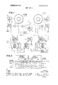
- FIG. 3 discloses a motor driver such as may be utilized as reel motor drivers 30 and 31 and capstan motor driver 32. These drivers consist essentially of a switching structure which, as commanded by its associated motor control logic, is effective to connect a DC motor to a source of DC supply.
- file reel motor 25 is shown connected in a fourtransistor bridge network. When transistors T1 and T4 are conductive, motor 25 is energized to turn clockwise to move tape into file column 14. When only transistor T3 is conductive, a dynamic brake circuit for clockwise motor rotation is efiective to short the motor armature through transistor T3 and diode 64. When only transistor T4 is conductive, a coast mode of operation is instituted for clockwise rotation.
- the transistor network of FIG. 3 may be controlled by reel motor control logic network, a portion of which is disclosed in simplified form in FIG. 4.
- AND gates 35, 36 and 37 are connected to file column sensors R1 and R2 to selectively provide the three zone outputs of FIG. 2 on conductors 38, 39 and 40.
- An output on conductor 38 indicates that the tape loop is above sensor R1.
- An output on conductor 39 indicates that the tape loop is in between sensore R1 and R2.
- An output on conductor 40 indicates that the tape loop is below sensor R2.
- Sensors R1 and R2 may be pressure responsive sensors in the form of switches which provide output signals in accordance with the pressure at the sensor.
- This pressure may be either atmospheric or vacuum, as the tape loop is below or above the sensor.
- this sensor will be subjected to atmospheric pressure and can for example, provide a negative potential output signal from that respective sensor.
- the sensor is subjected to a vacuum and the output signal then provided may be of a positive potential.
- the positive signal on conductor 39 is inverted by inverter 33 and 34 and is effective to inhibit gates 36 and 37.
- FIG. 4 discloses only a portion of the file reel motor control logic 23.
- Conductor 50 is positive when forward (CCW) rotation of capstan 10 is desired.
- conductor 51 is positive.
- File reel slow conductor 52 and file reel fast conductor 53 provide positive signals respectively when the tape speed at the file reel is slower or faster than the tape speed at the capstan.
- FIG. 4 is shown by way of a simplified example of a structure which may be utilized to accomplish the control logic to control reel motors 24 and 25.
- FIG. 4 does not accomplish all of the modes of operation of file motor 25 identified in FIG. 2.
- the teaching of FIG. 4 can be extended to accomplish the requirements of FIG. 2, as will be apparent to those skilled in the art.
- capstan motor control logic for capstan motor likewise is accomplished by the use of gates which respond to the signals on lines 50 and 51 to control driver 32 and produce the required direction of capstan rotation.
- a magnetic tape unit having tape buffer means, reversible capstan means disposed to supply tape to one side of said bufi'er means, and reversible reel means disposed to supply tape to the other side of said buffer means, the improvement comprising:
- reel control means responsive to the quantity of tape in said buffer means and to the direction of rotation of said capstan means, and connected in controlling relation to said reel means;
- said reel control means being effective to maintain a minimum quantity of tape in said buffer means when said capstan means is removing tape therefrom by instituting a drive mode of operation for said reel means to move tape into said bufier means when the quantity of tape in said buffer means is less than said minimum quantity, and to instituting a brake mode of operation for said reel means when the quantity of tape in said buffer means is more than said minimum quantity;
- said reel control means being effective to maintain a maximum quantity of tape in said buffer means when said capstan means is moving tape thereinto, by instituting a drive mode of operation for said reel means to remove tape from said bufier means when the quantity of tape is greater than said maximum quantity, and to institute a brake mode of operation when the quantity of tape in said bufier means is less than said maximum quantity;
- means responsive to the direction in which the quantity of tape in said bufier means is changing, including means difierentially sensing the tape speed on opposite sides of said buffer means, connected to modify the operation of said reel control means to inhibit the drive mode of operation of said reel means whenever said reel means is moving tape faster than said capstan means is moving tape and to additionally inhibit the brake mode of operation of said reel means when said reel means is moving tape slower than said capstan means is moving tape and said capstan means is removing tape from said buffer means.
- a magnetic tape unit as defined in claim 2 wherein said means responsive to the direction in which the quantity of tape in said buffer means is changing includes a first tachometer driven by said capstan, a second tachometer driven by the tape on the reel means side of said bufier means, and means comparing the outputs of said tachometers.
- a magnetic tape unit having a vacuum column, a tape reel located on one side of the vacuum column, a motor connected to said reel, and a bidirectionally rotatable capstan located on the other side of the vacuum column, the improvement comprising:
- sensing means including two position sensors, providing binary outputs, spaced along the vacuum column to define an upper, an intermediate and a lower zone therein;
- logic means controlled by the binary outputs of said position sensors and by the direction of rotation of the capstan, and connected to control the reel motor to institute a drive mode of operation for the motor in a direction to move tape into said column when the loop is in the upper zone and the capstan is removing tape from said column; to institute a drive mode of operation for the motor in a direction to move tape out of said column when the loop is in the lower zone and the capstan is moving tape into said column; and to institute the brake mode of operation for the motor when the loop is in the intennediate zone; and
- speed comparing means responsive to the speed of the tape on the reel side and on the capstan side of the vacuum column, and providing a binary output which is connected to control said logic means, said binary output having one state which is effective to inhibit said drive modes when the speed of the tape on the reel side of the vacuum column is the higher speed, and having a second state which is compared to the binary signal source indicative of the direction of capstan rotation to selectively inhibit said brake mode when the speed of the tape on the capstan side of the vacuum column is the higher speed and the direction of rotation of said capstan is such as to remove tape from the vacuum column;
- said speed comparing means including first and second digital tachometers, one of which is driven in accordance with the speed of the tape adjacent the reel and the other of which is driven in accordance with the speed of the tape at the capstan, and frequency comparator means having input means connected to said tachometer and providing said binary output.
- a magnetic tape unit having a file reel, a motor connected thereto, a file vacuum column adjacent said file reel, a machine reel, a motor connected thereto, a machine vacuum column adjacent said machine reel, and capstan means disposed intermediate said vacuum columns, the improvement comprising:
- first and second position sensing means including two spaced position sensors in each of said vacuum columns to define an upper, an intennediate and a lower zone in each column, each of said sensors providing a binary output in accordance with the loop position;
- first and second logic means controlled by said first and second position sensing means respectively and by the direction in which said capstan means is moving tape; means connecting said first and second logic means in controlling relation to said file reel motor and said machine reel motor to institute the following control order for said motors when said capstan is moving tape in a forward direction from said file reel to said machine reel;
- first and second speed comparing means including a first digital tachometer driven in accordance with the speed of the tape adjacent said capstan means, second and third digital tachometers driven in accordance with the speed of the tape adjacent a reel as compared to the speed of the tape adjacent the capstan means, said first and second speed comparing means being responsive to the difference between the speed of the tape on opposite sides of said file and machine vacuum columns respectively, and connected to said first and second logic means, respectively, to inhibit the drive mode of that reel motor whose tape speed on the reel side of its vacuum column is the higher speed, and to inhibit the brake mode of said file reel motor when the tape speed on the capstan means side of said file vacuum column is the higher speed; and means connecting said first and second logic means in controlling relation to said file reel motor and said machine reel motor to institute the following control order for said motors when said capstan is moving tape in a backward direction from said machine reel to said file reel;
- said first and second comparing means bemg additionally effective to inhibit the brake mode of said machine reel motor when the tape speed on the capstan means side of said machine vacuum column is the higher speed.
Landscapes
- Controlling Rewinding, Feeding, Winding, Or Abnormalities Of Webs (AREA)
- Control Of Multiple Motors (AREA)
- Control Of Electric Motors In General (AREA)
- Control Of Direct Current Motors (AREA)
Applications Claiming Priority (1)
| Application Number | Priority Date | Filing Date | Title |
|---|---|---|---|
| US8199370A | 1970-10-19 | 1970-10-19 |
Publications (1)
| Publication Number | Publication Date |
|---|---|
| US3673473A true US3673473A (en) | 1972-06-27 |
Family
ID=22167712
Family Applications (1)
| Application Number | Title | Priority Date | Filing Date |
|---|---|---|---|
| US81993A Expired - Lifetime US3673473A (en) | 1970-10-19 | 1970-10-19 | Magnetic tape unit reel motor tension control |
Country Status (4)
| Country | Link |
|---|---|
| US (1) | US3673473A (member.php) |
| JP (1) | JPS5385B1 (member.php) |
| DE (1) | DE2151383A1 (member.php) |
| FR (1) | FR2144176A5 (member.php) |
Cited By (13)
| Publication number | Priority date | Publication date | Assignee | Title |
|---|---|---|---|---|
| US3916441A (en) * | 1974-07-01 | 1975-10-28 | Ampex | Tape transport having variable torque constant reel and capstan drive motor |
| US3961500A (en) * | 1974-10-15 | 1976-06-08 | Gould Inc. | Yarn runner-length controller for knitting machines |
| US3982160A (en) * | 1974-03-14 | 1976-09-21 | Rca Corporation | System for controlling tension of magnetic tape |
| US3984065A (en) * | 1975-03-13 | 1976-10-05 | Computer Peripherals, Inc. | Tape transport system |
| US4051415A (en) * | 1975-03-05 | 1977-09-27 | Braemar Computer Devices, Inc. | Web speed control system |
| US4063139A (en) * | 1975-04-14 | 1977-12-13 | General Electric Company | Tape drive motor control circuit |
| US4065074A (en) * | 1976-06-02 | 1977-12-27 | Sperry Rand Corporation | Reel servo control system |
| US4405883A (en) * | 1980-07-30 | 1983-09-20 | Victor Company Of Japan, Ltd. | Apparatus for stopping rotation of tape reels |
| US4513229A (en) * | 1982-09-17 | 1985-04-23 | Ampex Corporation | Reel servo for tape transport |
| US4589603A (en) * | 1983-01-21 | 1986-05-20 | Grapha-Holding Ag | Apparatus for temporary storage of a stream of partially overlapping sheets |
| US5082435A (en) * | 1989-06-23 | 1992-01-21 | Yoshida Industry Co., Ltd. | Transferring and molding apparatus |
| US5228635A (en) * | 1990-01-26 | 1993-07-20 | Sony Corporation | Apparatus having a vacuum chamber for controlling a tape tension thereof/vacuum chamber apparatus for controlling tape tension |
| US20030025469A1 (en) * | 2001-08-01 | 2003-02-06 | Zhenjia Zhou | Moving body drive control device |
Families Citing this family (3)
| Publication number | Priority date | Publication date | Assignee | Title |
|---|---|---|---|---|
| DE2529146C3 (de) * | 1975-06-30 | 1978-08-24 | Siemens Ag, 1000 Berlin Und 8000 Muenchen | Verfahren und Anordnung zum Verhindern von Auf- oder Abwickel- oder Umkehrbefehlen für einen Wickelmotor in einem Bandgerät, dessen Drehzahl einen bestimmten Wert unterschreitet |
| DK149352C (da) * | 1979-01-11 | 1986-11-03 | Eskofot As | Fremgangsmaade til indstilling af et forstoerrelsesapparat |
| JPS6064097U (ja) * | 1983-10-07 | 1985-05-07 | 林 貴市 | たばこ消し具 |
Citations (1)
| Publication number | Priority date | Publication date | Assignee | Title |
|---|---|---|---|---|
| US3370802A (en) * | 1965-06-04 | 1968-02-27 | Sperry Rand Corp | Tape loop control circuit |
-
1970
- 1970-10-19 US US81993A patent/US3673473A/en not_active Expired - Lifetime
-
1971
- 1971-09-14 JP JP7098671A patent/JPS5385B1/ja active Pending
- 1971-09-16 FR FR7133813A patent/FR2144176A5/fr not_active Expired
- 1971-10-15 DE DE19712151383 patent/DE2151383A1/de active Pending
Patent Citations (1)
| Publication number | Priority date | Publication date | Assignee | Title |
|---|---|---|---|---|
| US3370802A (en) * | 1965-06-04 | 1968-02-27 | Sperry Rand Corp | Tape loop control circuit |
Cited By (15)
| Publication number | Priority date | Publication date | Assignee | Title |
|---|---|---|---|---|
| US3982160A (en) * | 1974-03-14 | 1976-09-21 | Rca Corporation | System for controlling tension of magnetic tape |
| US3916441A (en) * | 1974-07-01 | 1975-10-28 | Ampex | Tape transport having variable torque constant reel and capstan drive motor |
| US3961500A (en) * | 1974-10-15 | 1976-06-08 | Gould Inc. | Yarn runner-length controller for knitting machines |
| US4051415A (en) * | 1975-03-05 | 1977-09-27 | Braemar Computer Devices, Inc. | Web speed control system |
| US3984065A (en) * | 1975-03-13 | 1976-10-05 | Computer Peripherals, Inc. | Tape transport system |
| DE2610053A1 (de) * | 1975-03-13 | 1976-10-14 | Control Data Corp | Bandtransportvorrichtung |
| US4063139A (en) * | 1975-04-14 | 1977-12-13 | General Electric Company | Tape drive motor control circuit |
| US4065074A (en) * | 1976-06-02 | 1977-12-27 | Sperry Rand Corporation | Reel servo control system |
| US4405883A (en) * | 1980-07-30 | 1983-09-20 | Victor Company Of Japan, Ltd. | Apparatus for stopping rotation of tape reels |
| US4513229A (en) * | 1982-09-17 | 1985-04-23 | Ampex Corporation | Reel servo for tape transport |
| US4589603A (en) * | 1983-01-21 | 1986-05-20 | Grapha-Holding Ag | Apparatus for temporary storage of a stream of partially overlapping sheets |
| US5082435A (en) * | 1989-06-23 | 1992-01-21 | Yoshida Industry Co., Ltd. | Transferring and molding apparatus |
| US5228635A (en) * | 1990-01-26 | 1993-07-20 | Sony Corporation | Apparatus having a vacuum chamber for controlling a tape tension thereof/vacuum chamber apparatus for controlling tape tension |
| US20030025469A1 (en) * | 2001-08-01 | 2003-02-06 | Zhenjia Zhou | Moving body drive control device |
| US6841955B2 (en) * | 2001-08-01 | 2005-01-11 | Ohi Seisakusho Co., Ltd. | Moving body drive control device |
Also Published As
| Publication number | Publication date |
|---|---|
| JPS5385B1 (member.php) | 1978-01-05 |
| JPS477966A (member.php) | 1972-04-27 |
| DE2151383A1 (de) | 1972-04-20 |
| FR2144176A5 (member.php) | 1973-02-09 |
Similar Documents
| Publication | Publication Date | Title |
|---|---|---|
| US3673473A (en) | Magnetic tape unit reel motor tension control | |
| US2952415A (en) | Tape transport system | |
| US3293522A (en) | Motor drive circuits | |
| US4065074A (en) | Reel servo control system | |
| US3876168A (en) | Motor control for tape transport system | |
| US3648134A (en) | Reel servosystem | |
| US3122687A (en) | Servo control system | |
| GB946428A (en) | Servo positioning mechanism | |
| US4072883A (en) | Bi-directional motor drive servo | |
| US3370802A (en) | Tape loop control circuit | |
| US2708554A (en) | Tape drive and recording apparatus | |
| US3672600A (en) | Reel-to-reel tape storage apparatus | |
| US3246218A (en) | Plural motor dual speed positioning system transition control | |
| GB1122536A (en) | Improvements in electric motor control systems | |
| US3829745A (en) | Techniques for maintaining substantially constant tension in web | |
| US3773275A (en) | Reel control for a tape transport system | |
| US3440630A (en) | Data gap predictor for magnetic tape units | |
| US3311313A (en) | Tape rewind system | |
| US3135447A (en) | Tape reader control device | |
| US3550878A (en) | Digital position detection and velocity compensation system | |
| US3319901A (en) | Loop control system for tape transports | |
| US3411061A (en) | Fast critically damped motor drive system | |
| US3495151A (en) | Memory control circuit for clutching,braking and reversing a motor | |
| US3394854A (en) | Tape transport control circuits | |
| JPS634254B2 (member.php) |