US3668547A - Frequency-stabilized laser arrangement - Google Patents
Frequency-stabilized laser arrangement Download PDFInfo
- Publication number
- US3668547A US3668547A US122796A US3668547DA US3668547A US 3668547 A US3668547 A US 3668547A US 122796 A US122796 A US 122796A US 3668547D A US3668547D A US 3668547DA US 3668547 A US3668547 A US 3668547A
- Authority
- US
- United States
- Prior art keywords
- laser
- frequency
- potentiometer
- photo
- logic circuit
- Prior art date
- Legal status (The legal status is an assumption and is not a legal conclusion. Google has not performed a legal analysis and makes no representation as to the accuracy of the status listed.)
- Expired - Lifetime
Links
Images

Classifications
-
- H—ELECTRICITY
- H01—ELECTRIC ELEMENTS
- H01S—DEVICES USING THE PROCESS OF LIGHT AMPLIFICATION BY STIMULATED EMISSION OF RADIATION [LASER] TO AMPLIFY OR GENERATE LIGHT; DEVICES USING STIMULATED EMISSION OF ELECTROMAGNETIC RADIATION IN WAVE RANGES OTHER THAN OPTICAL
- H01S3/00—Lasers, i.e. devices using stimulated emission of electromagnetic radiation in the infrared, visible or ultraviolet wave range
- H01S3/10—Controlling the intensity, frequency, phase, polarisation or direction of the emitted radiation, e.g. switching, gating, modulating or demodulating
- H01S3/13—Stabilisation of laser output parameters, e.g. frequency or amplitude
- H01S3/139—Stabilisation of laser output parameters, e.g. frequency or amplitude by controlling the mutual position or the reflecting properties of the reflectors of the cavity, e.g. by controlling the cavity length
- H01S3/1398—Stabilisation of laser output parameters, e.g. frequency or amplitude by controlling the mutual position or the reflecting properties of the reflectors of the cavity, e.g. by controlling the cavity length by using a supplementary modulation of the output
Definitions
- ABSTRACT A laser arrangement for the stabilization of the frequency of a one or two mode gas laser, particularly a short He-Ne laser, where the stimulated medium is arranged between a fixed mirror and a mirror which is displaceable by means of a piezoceramic in the axial direction of the laser, the laser beams discharging from the partially transparent fixed mirror being used to generate a DC voltage control signal which is proportional to the frequency deviation of the laser beams with respect to the central frequency of the amplifying transfer, returning the resonator to the central frequency by way of the piezo-ceramic, in the control circuit which contains a photosensitive element and subsequent amplifiers and phase 7 at least partially, in a magnetic coil which is excited to generate an axis-parallel alternating magnetic field.
- a A4 plate and a polarization device are arranged between the fixed partially transparent mirror and the photo-sensitive element.
- This invention relates to a laser arrangement for stabilizing the frequency of a one or two mode gas laser, particularly a short I-le-Ne laser, where the stimulated medium is arranged between a fixed mirror and a mirror which is mounted on a piezo-ceramic element and which is displaceable in the axial direction of the laser, wherein the laser beams discharging from the partially transparent fixed mirror are employed to generate a DC voltage control signal which is proportional to the frequency deviation of the laser beams with respect to the central frequency of the amplifying transfer, returning the resonator to the central frequency by way of the piezo-ceramic element, the control circuit containing a photo-sensitive element and subsequent amplifiers and phase demodulator components.
- a debilitation fluctuating at the rhythm of the frequency of the magnetic field in the absorption tube of the laser beam results during passage through the absorption tube, whose amplitude is proportional to a certain deviation of the laser frequency from the central frequency v to the amount of the deviation.
- the amplitude of the AC wave caused by a laser beam so modulated in a photo element, a photo diode for example can be used as a control signal for the shifting of the laser mirror which is positioned on a piezo-ceramic in order to tune the laser to the central frequency v,,.
- the present invention has as its primary objective, therefore, the provision of a frequency stabilized laser arrangement which is considerably less expensive and makes possible an equally good control quality as the arrangements of the prior art with absorption cells.
- the foregoing objective is realized in a laser arrangement of the above-mentioned kind by a construction wherein the stimulated medium is arranged, or at least partially arranged, in a magnetic coil which generates an axis-parallel alternating magnetic field, and a M4 plate and a polarization device are arranged between the fixed partially transparent mirror and the photo-sensitive element.
- the laser beams break up into two highly coupled oscillations which extend in opposite directions.
- the direction of rotation of the individual ones depends on the direction of the axial magnetic field in the laser tube.
- the intensity of the right-circular polarized radiation (RZP) of the negative and positive axial magnetic field is of different magnitudes.
- the intensity of the right-circular wave (RZP) depends on the time-wise course of the magnetic field.
- the time-wise course of the intensity of the right-circular wave (RZP) for a laser frequency v, v, and a laser frequency v v differs in phase by 1r.
- the left-circular polarized radiation acts in the same manner. This property of the left-circular and right-circular radiation in the alternating magnetic field is utilized as control criteria for the stabilization of the laser frequency, because the position of the laser frequency is given by the degree and phase of the intensity modulation.
- the magnetic coil forms the inductence of an electrical oscillation circuit operated by a resonance amplifier.
- the arrangements according to the present invention and to those operating with an electro-optical polarization switch or an absorption cell permit a control only in the range where the differences in intensity of the circular waves are clearly connected with the deviation of the laser frequency from the central position which approximately corresponds with the distance of the maxima of both profiles for left and right-circular polarized radiation it is possible upon turning on the laser that the radiation occurring comes to be located outside the laser in an additional control range, hereinafter called the holding range, so that the control circuit cannot operate.
- an electric motor which is controlled by a logic circuit which applies, in this case via a potentiometer, a variable DC voltage from an additional source to the piezo-ceramic and varies this voltage until the frequency of the laser resonator corresponds approximately with the central frequency v,,. It is preferable that this is accomplished through the aforementioned logic circuit which controls the magnitude of the amplified photo element voltage which is demodulated correctly in phase and starts the motor when a certain magnitude is exceeded, which means that the laser line undergoes a very strong shift.
- a logic circuit which controls the magnitude of the amplified photo element voltage which is demodulated correctly in phase and starts the motor when a certain magnitude is exceeded, which means that the laser line undergoes a very strong shift.
- the additional control monitored by the motor connected to the potentiometer having moved very close to one of its two stops, at second logic circuit provides for a return of the potentiometer to the central position.
- This operation which interrupts the synchronization of the laser for a short time is reported externally of the system, preferably by an indication device, for example, a buuer or an optical reading device controlled by the second logic circuit.
- an indication device for example, a buuer or an optical reading device controlled by the second logic circuit.
- the interruption of the synchronization and the return of the potentiometer need not interfere, even if the laser is operated continuously for days, in that the principal source of interference for such major deviations is eliminated in a laser system according to the invention by a good thermal compensation of the laser.
- apparatus controlled by the second logic circuit are provided which block the catching and holding automatically during a return of the potentiometer. The laser is again stabilized automatically after the return of the potentiometer.
- a control system is also appropriate for frequency stabilization of the laser if two inherent frequencies occur during the search operation.
- the oscillation which is stronger in intensity is trapped first and shifted in the direction of the central frequency v, whereby the second possible form of oscillation is also shifted, so that it drops out of the profile of the laser line and can, therefore, no longer be amplified.
- FIG. I is a graphical illustration of the intensity for right-circular polarized and left-circular polarized radiation of a gas laser as a function of the laser frequency v for the different directions of magnetic field illustrated in FIG. la and FIG. lb;
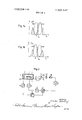
- FIG. 2 is a schematic representation of a simple stabilized laser arrangement according to the present invention without the provision of the additional automatic search apparatus;
- FIG. 3 is a schematic diagram of a frequency-stabilized laser arrangement according to the invention particularly illustrating automatic search and return of the potentiometer.
- a laser tube 1 filled with, for example, a l-Ie-Ne mixture is arranged between a solid partially transparent mirror 2 and a mirror 3 which is secured to a piezoceramic body 4.
- the laser provides two circular-polarized laser beams R2? and LZP which are converted with a M4 plate 5 into two linear polarized intensity modulated waves disposed perpendicularly to one another.
- a signal is produced after demodulation of the linear polarized and intensity modulated waves with a photo diode 10, said signal having the frequency of the alternating magnetic field provided by the coil 7.
- the output signal of the photo diode I0 is amplified in a selective amplifier 11 and fed to a phase sensitive demodulator circuit. In this circuit the signal is compared in amplitude and phase with the control signal of the oscillator 9, whereby a DC voltage independent of the laser frequency is produced.
- the DC voltage for a laser frequency v, v, and for a laser frequency V v differs in polarity.
- This DC voltage which is independent of laser frequency is fed by way of a low pass filter 13 and a DC voltage amplifier 14 to the piezo-ceramic 4 in the laser resonator for correction of the mirror position, in order to thereby stabilize the laser frequency.
- the change of the resonator length of the laser thereby causes shifts in the laser frequency in the direction of the central frequency v,,.
- the laser tube 1 is located in a coil 7 which forms the inductance of an electrical oscillation circuit operated by a resonance amplifier 8.
- the resonance amplifier 8 is in turn operated in a similar manner by an oscillator 9.
- a housing 60 is provided to envelope the laser arrangement and bounce the piezo-ceramic 4 and the mirror 2.
- FIG. 3 schematically represents the design of a laser stabilization circuit according to the invention, which circuit comprises automatic search and return of a potentiometer 27.
- the apparatus of FIG. 3 includes, in addition to additional amplifiers 15, 16 and 17, a phase correction member 20 which has been inserted between the oscillator 9 and the demodulator circuit 19 which compensates the phase shiftings produced in the amplifiers.
- Dependlogic circuit 24 responds and, depending on the polarity of the voltage, the logic circuit 24 controls a motor switch 25, so that a motor 26 rotates either forward or reverse, thereby opening or closing a helipot 27.
- a more or less large DC voltage is produced at the output of a DC voltage amplifier 2B, fed by an oscillator 29, said voltage shifting the mirror 3 connected to the piezo-crystal 4 until the resonance frequency of the laser resonator approximately corresponds to the frequency v,,.
- the DC voltage amplifiers 22 and 23 are blocked by the amplifier 30 which is also operated by the oscillator 29, and controlled in turn by an OR switch 35 which responds to the voltages of the trigger circuits 31, 32, 33 and 34.
- the motor search circuit operates until the laser frequency has approximated the central frequency v so closely that the output voltage of the amplifier 21 has dropped below the tearoff voltages of the trigger circuits 31 and 34 of the logic circuit 24.
- a second logic circuit 36 is connected to the sliding contact and one of the terminal tappings of the helipot 27 and is used to reset the sliding contact to the central portion as the contact approaches one of the end stops.
- the response of the second circuit 36 signals, on the one hand, to the outside of the equipment by means of a signaling device controlled by a trigger circuit 37 (a buzzer or a lamp, for example), and on the other hand, the photo element voltage amplifier is blocked by way of an OR circuit 38 and a subsequent transistor switch 39. Since the return of the helipot 27 into its central position is also brought about by way of conductors 40 and 41 with the help of the first logic circuit 24, the amplifier 30 is again blocked.
- a trigger circuit 37 a buzzer or a lamp, for example
- a laser arrangement for stabilizing the frequency of a gas laser, particularly a short He-Ne laser, wherein the stimulated medium is positioned between a partially transparent fixed mirror and a displaceable mirror mounted on a piezoceramic and displaceable in the axial direction of the laser, wherein the laser beams discharging from the partially transparent fixed mirror are utilized to generate a DC control signal proportional to the frequency deviation of the laser beams with respect to the central frequency v, of the amplifying transfer, the control signal being utilized to return the resonator to the central frequency v via the piezo-ceramic, the improvement therein comprising a coil disposed about the laser and energizable to generate an axis-parallel alternating magnetic field, a M4 plate and a polarization device disposed to receive laser beams from the partially transparent fixed mirror, a photo-sensitive element for receiving polarized laser beams from said polarization device and responsive thereto to produce an output signal for controlling the energization of said coil
- a resonance amplifier which includes said coil as the inductance thereof.
- a laser arrangement further comprising a potentiometer, an electric motor for operating said potentiometer, a logic circuit for operating said motor in accordance with the signal produced by said photo-sensitive element, said potentiometer being connected in circuit with said piezo-ceramic to provide an additional DC voltage thereto when the laser frequency is outside of the control range of the photo-sensitive element control circuit.
- demodulation means connected between said photo-sensitive element and said logic circuit, said logic circuit being operable to insure that the photo-element voltage has been demodulated correctly at phase.
- said second logic circuit includes means for inhibiting said first logic circuit during the return movement of said potentiometer, and comprising means for rendering the output of said photo-sensitive means inefiective during the return movement of said potentiometer.
Applications Claiming Priority (1)
| Application Number | Priority Date | Filing Date | Title |
|---|---|---|---|
| DE19702015612 DE2015612A1 (de) | 1970-04-01 | 1970-04-01 | Frequenzstabilisierte Laseranordnung |
Publications (1)
| Publication Number | Publication Date |
|---|---|
| US3668547A true US3668547A (en) | 1972-06-06 |
Family
ID=5766844
Family Applications (1)
| Application Number | Title | Priority Date | Filing Date |
|---|---|---|---|
| US122796A Expired - Lifetime US3668547A (en) | 1970-04-01 | 1971-03-10 | Frequency-stabilized laser arrangement |
Country Status (4)
| Country | Link |
|---|---|
| US (1) | US3668547A (de) |
| DE (1) | DE2015612A1 (de) |
| FR (1) | FR2085764A1 (de) |
| GB (1) | GB1327708A (de) |
Cited By (6)
| Publication number | Priority date | Publication date | Assignee | Title |
|---|---|---|---|---|
| US3801929A (en) * | 1972-07-31 | 1974-04-02 | Asahi Optical Co Ltd | Gas laser apparatus having low temperature sensitivity |
| US3831108A (en) * | 1972-04-21 | 1974-08-20 | Anvar | Method of frequency and intensity stabilization of the radiation emitted by a high-power gas laser and a gas laser for the application of said method |
| US3899748A (en) * | 1971-09-27 | 1975-08-12 | Siemens Ag | Method for the frequency stabilization of a laser |
| CN104701727A (zh) * | 2015-03-02 | 2015-06-10 | 北京大学 | 一种激光稳频方法及装置 |
| US20160146909A1 (en) * | 2013-08-02 | 2016-05-26 | Hitachi, Ltd. | Magnetic field measurement device |
| CN108649421A (zh) * | 2018-06-05 | 2018-10-12 | 河南师范大学 | 基于塞曼效应的新型激光器稳频装置 |
Families Citing this family (1)
| Publication number | Priority date | Publication date | Assignee | Title |
|---|---|---|---|---|
| US3753150A (en) * | 1972-09-06 | 1973-08-14 | Avco Corp | Laser mirror positioning apparatus |
Citations (3)
| Publication number | Priority date | Publication date | Assignee | Title |
|---|---|---|---|---|
| US3534292A (en) * | 1967-08-02 | 1970-10-13 | Hewlett Packard Co | Frequency stabilized laser system |
| US3594659A (en) * | 1967-02-08 | 1971-07-20 | Inst Angewandte Physik | Device for the frequency stabilization of a gas laser oscillator |
| US3596201A (en) * | 1970-06-08 | 1971-07-27 | Hughes Aircraft Co | Frequency stabilized laser |
-
1970
- 1970-04-01 DE DE19702015612 patent/DE2015612A1/de active Pending
-
1971
- 1971-03-10 US US122796A patent/US3668547A/en not_active Expired - Lifetime
- 1971-03-31 FR FR7111259A patent/FR2085764A1/fr not_active Withdrawn
- 1971-04-19 GB GB2578071*A patent/GB1327708A/en not_active Expired
Patent Citations (3)
| Publication number | Priority date | Publication date | Assignee | Title |
|---|---|---|---|---|
| US3594659A (en) * | 1967-02-08 | 1971-07-20 | Inst Angewandte Physik | Device for the frequency stabilization of a gas laser oscillator |
| US3534292A (en) * | 1967-08-02 | 1970-10-13 | Hewlett Packard Co | Frequency stabilized laser system |
| US3596201A (en) * | 1970-06-08 | 1971-07-27 | Hughes Aircraft Co | Frequency stabilized laser |
Cited By (8)
| Publication number | Priority date | Publication date | Assignee | Title |
|---|---|---|---|---|
| US3899748A (en) * | 1971-09-27 | 1975-08-12 | Siemens Ag | Method for the frequency stabilization of a laser |
| US3831108A (en) * | 1972-04-21 | 1974-08-20 | Anvar | Method of frequency and intensity stabilization of the radiation emitted by a high-power gas laser and a gas laser for the application of said method |
| US3801929A (en) * | 1972-07-31 | 1974-04-02 | Asahi Optical Co Ltd | Gas laser apparatus having low temperature sensitivity |
| US20160146909A1 (en) * | 2013-08-02 | 2016-05-26 | Hitachi, Ltd. | Magnetic field measurement device |
| US10162021B2 (en) * | 2013-08-02 | 2018-12-25 | Hitachi, Ltd. | Magnetic field measurement device |
| CN104701727A (zh) * | 2015-03-02 | 2015-06-10 | 北京大学 | 一种激光稳频方法及装置 |
| CN104701727B (zh) * | 2015-03-02 | 2018-01-09 | 北京大学 | 一种激光稳频方法及装置 |
| CN108649421A (zh) * | 2018-06-05 | 2018-10-12 | 河南师范大学 | 基于塞曼效应的新型激光器稳频装置 |
Also Published As
| Publication number | Publication date |
|---|---|
| DE2015612A1 (de) | 1971-10-21 |
| FR2085764A1 (de) | 1971-12-31 |
| GB1327708A (en) | 1973-08-22 |
Similar Documents
| Publication | Publication Date | Title |
|---|---|---|
| US4193029A (en) | Pulsed helium magnetometer | |
| US3495161A (en) | Optically driven atomic resonator systems employing means for modulating the sense of rotational polarization of the pumping light | |
| US3584292A (en) | Apparatus for optically monitoring the gyromagnetic resonance of quantum systems | |
| US6993058B2 (en) | Coherent population trapping detector | |
| US3628173A (en) | Laser mode selection and stabilization apparatus employing a birefringement etalon | |
| US3899748A (en) | Method for the frequency stabilization of a laser | |
| US3668547A (en) | Frequency-stabilized laser arrangement | |
| US2955262A (en) | Gas cell for frequency selective system | |
| US3453557A (en) | Laser stabilization apparatus | |
| US3534292A (en) | Frequency stabilized laser system | |
| US4964132A (en) | Laser arrangement with frequency stabilized and intensity stabilized laser emission | |
| US2337251A (en) | Alternating current relay | |
| US4462006A (en) | Method for stabilizing the resonance frequency of a rubidium frequency standard | |
| US3879130A (en) | Method and apparatus for the operation of ring laser in a biased mode | |
| US3639855A (en) | Laser devices | |
| NL151856B (nl) | Inrichting voor het moduleren van de straling van een laser. | |
| US3537027A (en) | Frequency-stabilized single mode ring lasers | |
| US3187251A (en) | Quantum oscillators | |
| US3496488A (en) | Frequency-stabilized optical maser | |
| US3436678A (en) | Laser capable of continuous frequency tuning | |
| Jitschin et al. | Fast frequency control of a cw dye jet laser | |
| US3471804A (en) | Frequency stabilized laser | |
| US2926311A (en) | Variable frequency signal generator | |
| US3001141A (en) | Source | |
| US3154739A (en) | Automatic frequency control system for high frequency transmitters |