US366314A - Thill-coupling - Google Patents
Thill-coupling Download PDFInfo
- Publication number
- US366314A US366314A US366314DA US366314A US 366314 A US366314 A US 366314A US 366314D A US366314D A US 366314DA US 366314 A US366314 A US 366314A
- Authority
- US
- United States
- Prior art keywords
- block
- hooks
- pins
- coupling
- hub
- Prior art date
- Legal status (The legal status is an assumption and is not a legal conclusion. Google has not performed a legal analysis and makes no representation as to the accuracy of the status listed.)
- Expired - Lifetime
Links
- 238000010168 coupling process Methods 0.000 title description 16
- 238000005859 coupling reaction Methods 0.000 title description 16
- 229920001971 elastomer Polymers 0.000 description 22
- 239000005060 rubber Substances 0.000 description 22
- 230000001808 coupling Effects 0.000 description 14
- 238000010276 construction Methods 0.000 description 4
- 239000002184 metal Substances 0.000 description 4
- 210000000826 Nictitating Membrane Anatomy 0.000 description 2
- 238000005266 casting Methods 0.000 description 2
- 238000007906 compression Methods 0.000 description 2
- 235000017423 hawthorn Nutrition 0.000 description 2
- 230000003534 oscillatory Effects 0.000 description 2
- 229920000136 polysorbate Polymers 0.000 description 2
Images
Classifications
-
- B—PERFORMING OPERATIONS; TRANSPORTING
- B62—LAND VEHICLES FOR TRAVELLING OTHERWISE THAN ON RAILS
- B62C—VEHICLES DRAWN BY ANIMALS
- B62C5/00—Draught assemblies
Definitions
- the object of this invention is to provide an improved coupling, by means ot' which thethills or poles of carriages may be secured to the running-gear, so that theyniay be readily removed or secured in place, so that all rattling will be avoided, and so that lost motion occasioned by wear of the parts may be taken up and the coupling at all times made to tit closely together.
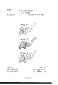
- Figure 1 is a side elevation of myimproved coupling.
- Fig. 2 is a section ofthe same.
- Fig. 3 is a side elevation with the side plate of the clip broken away and with the tightening device released.
- 2 represents a portion of a carriage-axle having a clip, 3, secured thereto.
- This clip forms one member of the coupling, and has projecting from its forward portion two hooks, 5.
- this strap 7 represents the strap that forms the other member of the coupling, and is secured in any suitable way to the thill or pole of the carriage.
- the lower end of this strap is in the form of a cylindrical hub, 8, having a pin, 9, projecting from each end thereof.
- This hub is adapted to fit between the two hooks 5,with the pins 9 engaging the said hooks, as shown in Fig. 1.
- These devices together form the parts of the coupling proper, the strain being taken bythe hooks from the pins 9. I combine with this device a means for locking the parts together while allowing the strap 7 to have an oscillatory movement about the axis formed by the pins 9 and the hooks 5.
- Asubstantially wedgeshaped casting, 11, is provided with forwardlyprojecting lugs 13, each having an oblong hole, 15, therein. These lugs embrace the ends of the hub 8 inside of the hooks 5, and the pins 9 project through holes 15.
- the rear face of the block 11 is provided with grooves or serrations 17, and the surface of the clip be tween the projecting hooks 5 is also provided with similar grooves.
- the opposite face of the block 11 has a rubber block, 19, secured thereto. I prefer to secure this rubber in position by means of a piece of thin metal, 21, that is secured at its lower end to the block 11, passes up the face of the rubber, and has its upper end bent over the upper edge of the rubber, as shown in Fig. 2.
- the holes 15 in the projections 13 are substantially in the direction ofthe length of the projections, or at right angles to the serrated face of the block 11, as shown in Fig. 3.
- the operation of the device will be readily understood.
- the pins 9 are brought into engagement with the hooks 5, and the serrated bloclr 11 is turned from the position shown in Fig. 3 to the position shown in Figsnl and 2.
- the rubber 19 is thereby closely compressed between the hub 8 and the block 11, and the pins 9 are held forward against the forward parts of the hooks.
- the serrated face of the block 11 engages the serrations in the face of the clip, and thereby the block is locked in posit-ion. While the device is in this position the pins are held closely against the hooks, so that the device cannot become uncoupled, and all rattling of the parts is prevented.
- the block 11 may be forced farther down, and thereby the hub 8 forced farther forward between the hooks. By this means the wear of the parts may be quickly taken up. While the metal strip 21 holds the rubber in place it does not prevent its be ing compressed or acting as a spring against the rear face of the hub S.
- I prefer to provide the upper edgeof the block 11 with a projecting lug7 25, under which a lever or wrench may be inserted and the block released from the serration on the clip by tirst further compressing the rub ber 19.
- the oblong holes 15 permit the block to be forced down to any desired point as they ride over the pins 9 and allow further compression of the rubber 19.
- the anti-rattling dcvice comprising the block 11, adapted to be pivoted upon the axis ofthe coupling and haw ing a rubber block, 19, secured to one face thereof, substantially as described.
Description
(No Modl.)
N. Wl HAWKBNSON.
THILL GOUPLING. 110.366,314. Patented July 12, 1887.Y
UNITE@ STATES ArnNr rtree.
NELS NV. IIAVKENSON, OF LITCHFIELD, MINNESOTA.
.THlLL-COUPLINGZ SPECIFICATION forming part. of Letters Patent No. 365,314, dated July 12, 1857.
(No model.)
.To @ZZ whom it may concern:
Be it known that l, NnLs W. Hawnnnson, of Litchfield, in the county7 of Meeker, State of Minnesota, have invented certain Improvements in Thill-Couplings, of which the following is a specification.
The object of this invention is to provide an improved coupling, by means ot' which thethills or poles of carriages may be secured to the running-gear, so that theyniay be readily removed or secured in place, so that all rattling will be avoided, and so that lost motion occasioned by wear of the parts may be taken up and the coupling at all times made to tit closely together.
My invention consists, generally, in the construction and combination hereinafter described, and pointed out in the claims.
In the accompanying drawings, forming a part of this specication, Figure 1 is a side elevation of myimproved coupling. Fig. 2 is a section ofthe same. Fig. 3 is a side elevation with the side plate of the clip broken away and with the tightening device released.
In the drawings, 2 represents a portion of a carriage-axle having a clip, 3, secured thereto. This clip forms one member of the coupling, and has projecting from its forward portion two hooks, 5.
7 represents the strap that forms the other member of the coupling, and is secured in any suitable way to the thill or pole of the carriage. The lower end of this strap is in the form of a cylindrical hub, 8, having a pin, 9, projecting from each end thereof. This hub is adapted to fit between the two hooks 5,with the pins 9 engaging the said hooks, as shown in Fig. 1. These devices together form the parts of the coupling proper, the strain being taken bythe hooks from the pins 9. I combine with this device a means for locking the parts together while allowing the strap 7 to have an oscillatory movement about the axis formed by the pins 9 and the hooks 5. Asubstantially wedgeshaped casting, 11, is provided with forwardlyprojecting lugs 13, each having an oblong hole, 15, therein. These lugs embrace the ends of the hub 8 inside of the hooks 5, and the pins 9 project through holes 15. The rear face of the block 11 is provided with grooves or serrations 17, and the surface of the clip be tween the projecting hooks 5 is also provided with similar grooves. The opposite face of the block 11 has a rubber block, 19, secured thereto. I prefer to secure this rubber in position by means of a piece of thin metal, 21, that is secured at its lower end to the block 11, passes up the face of the rubber, and has its upper end bent over the upper edge of the rubber, as shown in Fig. 2. The holes 15 in the projections 13 are substantially in the direction ofthe length of the projections, or at right angles to the serrated face of the block 11, as shown in Fig. 3.
The operation of the device will be readily understood. The pins 9 are brought into engagement with the hooks 5, and the serrated bloclr 11 is turned from the position shown in Fig. 3 to the position shown in Figsnl and 2. The rubber 19 is thereby closely compressed between the hub 8 and the block 11, and the pins 9 are held forward against the forward parts of the hooks. The serrated face of the block 11 engages the serrations in the face of the clip, and thereby the block is locked in posit-ion. While the device is in this position the pins are held closely against the hooks, so that the device cannot become uncoupled, and all rattling of the parts is prevented. As the pins and hooks become worn the block 11 may be forced farther down, and thereby the hub 8 forced farther forward between the hooks. By this means the wear of the parts may be quickly taken up. While the metal strip 21 holds the rubber in place it does not prevent its be ing compressed or acting as a spring against the rear face of the hub S. In order to release thelooking device I prefer to provide the upper edgeof the block 11 with a projecting lug7 25, under which a lever or wrench may be inserted and the block released from the serration on the clip by tirst further compressing the rub ber 19. The oblong holes 15 permit the block to be forced down to any desired point as they ride over the pins 9 and allow further compression of the rubber 19.
The details of construction of the device may be varied considerably without departing from IOCr ends of said hub and adapted to engage said hooks, thefserrated wedge-shaped block 11,and the rubber' 19, adapted to iit between said hub and the serrated surface of the clip and hold 5 said pins in said hooks and prevent rattling,
substantially as described.
2. rIhe combination, in a thill-couplng, with the hooks 5 and the pins 9 itting therein, of the hub 8, to which said pins are secured, the
re block 11, having the projections 13, embracing the ends of said hub, and the holes 15 in said projections engaging said pins 9, and the Vrubber block 19, secured to said block 11,sub stantially as described.
I5 3. Ina thillcoupling, the anti-rattling dcvice comprising the block 11, adapted to be pivoted upon the axis ofthe coupling and haw ing a rubber block, 19, secured to one face thereof, substantially as described.
4. The combination, in a thill-eoupling, of 2o the clip, having the hooks 5 and a serrated surface between said hooks, the hub 8, having the pins 9 engaging said hooks, the block 11, pivoted upon said pins 9 and provided with the serrations 17, and the rubber block 19, se- 25 cured to said block 11, substantially as dev scribed.
In testimony whereof I have hereunto set my hand this 27th day of April, 1887.
NELS IV. HAWKENSON.
In presence 01'- A. C. PAUL, S. J. BEARDsLEE.
Publications (1)
| Publication Number | Publication Date |
|---|---|
| US366314A true US366314A (en) | 1887-07-12 |
Family
ID=2435335
Family Applications (1)
| Application Number | Title | Priority Date | Filing Date |
|---|---|---|---|
| US366314D Expired - Lifetime US366314A (en) | Thill-coupling |
Country Status (1)
| Country | Link |
|---|---|
| US (1) | US366314A (en) |
-
0
- US US366314D patent/US366314A/en not_active Expired - Lifetime
Similar Documents
| Publication | Publication Date | Title |
|---|---|---|
| US366314A (en) | Thill-coupling | |
| US300057A (en) | Eobeet e | |
| US408976A (en) | Henry j | |
| US726202A (en) | Thill-coupling. | |
| US374566A (en) | Halp to james i | |
| US229047A (en) | John o | |
| US387460A (en) | William m | |
| US146124A (en) | coneice | |
| US797025A (en) | Thill-coupling. | |
| US425867A (en) | Anti-rattler for thill-couplings | |
| US205958A (en) | Improvement in thill-couplings | |
| US502972A (en) | X c calhoun l | |
| US540030A (en) | Thill-coupling | |
| US369689A (en) | Stephen buedsall | |
| US716513A (en) | Shaft-shackle for vehicles. | |
| US353656A (en) | Thill-coupling | |
| US225011A (en) | William haedee | |
| US434966A (en) | Thill-coupling | |
| US678184A (en) | Thill-coupling. | |
| US629488A (en) | Thill-coupling. | |
| US373174A (en) | Thill-coupling | |
| US200591A (en) | Improvement in thill-couplings | |
| US656875A (en) | Thill-coupling. | |
| US594626A (en) | Antirattle r for thill-couplings | |
| US626548A (en) | Thill-coupling |