US3663119A - Bladed rotors - Google Patents
Bladed rotors Download PDFInfo
- Publication number
- US3663119A US3663119A US26215A US3663119DA US3663119A US 3663119 A US3663119 A US 3663119A US 26215 A US26215 A US 26215A US 3663119D A US3663119D A US 3663119DA US 3663119 A US3663119 A US 3663119A
- Authority
- US
- United States
- Prior art keywords
- rotor
- low pressure
- pump
- actuator
- engine
- Prior art date
- Legal status (The legal status is an assumption and is not a legal conclusion. Google has not performed a legal analysis and makes no representation as to the accuracy of the status listed.)
- Expired - Lifetime
Links
- 239000012530 fluid Substances 0.000 claims abstract description 40
- 239000007788 liquid Substances 0.000 claims description 33
- 238000005461 lubrication Methods 0.000 claims description 15
- 229910001361 White metal Inorganic materials 0.000 description 4
- 238000007789 sealing Methods 0.000 description 4
- 239000010969 white metal Substances 0.000 description 4
- OKTJSMMVPCPJKN-UHFFFAOYSA-N Carbon Chemical compound [C] OKTJSMMVPCPJKN-UHFFFAOYSA-N 0.000 description 2
- 238000010276 construction Methods 0.000 description 2
- 230000004044 response Effects 0.000 description 2
- 229910000831 Steel Inorganic materials 0.000 description 1
- 229910052799 carbon Inorganic materials 0.000 description 1
- 238000002485 combustion reaction Methods 0.000 description 1
- 230000000694 effects Effects 0.000 description 1
- 230000001050 lubricating effect Effects 0.000 description 1
- 230000002093 peripheral effect Effects 0.000 description 1
- 230000037452 priming Effects 0.000 description 1
- 239000010959 steel Substances 0.000 description 1
Images


Classifications
-
- F—MECHANICAL ENGINEERING; LIGHTING; HEATING; WEAPONS; BLASTING
- F01—MACHINES OR ENGINES IN GENERAL; ENGINE PLANTS IN GENERAL; STEAM ENGINES
- F01D—NON-POSITIVE DISPLACEMENT MACHINES OR ENGINES, e.g. STEAM TURBINES
- F01D7/00—Rotors with blades adjustable in operation; Control thereof
-
- F—MECHANICAL ENGINEERING; LIGHTING; HEATING; WEAPONS; BLASTING
- F05—INDEXING SCHEMES RELATING TO ENGINES OR PUMPS IN VARIOUS SUBCLASSES OF CLASSES F01-F04
- F05D—INDEXING SCHEME FOR ASPECTS RELATING TO NON-POSITIVE-DISPLACEMENT MACHINES OR ENGINES, GAS-TURBINES OR JET-PROPULSION PLANTS
- F05D2260/00—Function
- F05D2260/70—Adjusting of angle of incidence or attack of rotating blades
- F05D2260/74—Adjusting of angle of incidence or attack of rotating blades by turning around an axis perpendicular the rotor centre line
-
- F—MECHANICAL ENGINEERING; LIGHTING; HEATING; WEAPONS; BLASTING
- F05—INDEXING SCHEMES RELATING TO ENGINES OR PUMPS IN VARIOUS SUBCLASSES OF CLASSES F01-F04
- F05D—INDEXING SCHEME FOR ASPECTS RELATING TO NON-POSITIVE-DISPLACEMENT MACHINES OR ENGINES, GAS-TURBINES OR JET-PROPULSION PLANTS
- F05D2260/00—Function
- F05D2260/70—Adjusting of angle of incidence or attack of rotating blades
- F05D2260/76—Adjusting of angle of incidence or attack of rotating blades the adjusting mechanism using auxiliary power sources
Definitions
- a bladed rotor having blading of flow-varying type including, carried within its hub, a pump operable upon rotor rotation and valve means for controlling the flow of pressure fluid from the pump to a fluid-pressure-operable actuator for adjusting the blading.
- Conduit means provided for conducting fluid to the pump inlet, are connectable to a source external of the rotor.
- a bladed rotor whose blading is of flow-varying type includes, carried within its hub, a pump operable upon rotor rotation, valve means for controlling the flow of pressure fluid from said pump to a fluid-pressureoperable actuator for adjusting the blading, and conduit means for conducting fluid to the inlet of the pump, said conduit means being connectible to a source external of the rotor.
- the conduit means is connectible to the source by way of fluid transfer means whereby fluid can pass from non-rotatable structure to the rotor.
- conduit means may be connected to the lubrication system of an engine which is connected to drive the bladed rotor.
- conduit means may be provided whereby fluid exhausting from said actuator can be directed through said fluid transfer means to said lubrication system.
- the pump may be of the internally-meshing lobed type and the axis of its drive shaft may be coincident with the axis of rotation of the rotor.
- the actuator may be of the vane-type and drive means from the actuator for adjusting the blading may include a balanced bevel gear train.
- the valve means may be arranged coaxially with respect to the actuator and within a hub portion thereof.
- the flow-varying blading is preferably of variable-pitch.
- FIG. 1 shows a gas turbine engine of the by-pass type having a bladed rotor, which forms a by-pass fan, shown partly in cross-section;
- FIG. 2 is a cross-section of a gear casing forming part of the construction shown in FIG. 1;
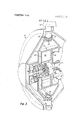
- FIG. 3 is a perspective view with parts cut away, of the rotary control valve, a vane actuator and the pitch-change pump for the rotor.
- a bladed rotor 11 includes seventeen blades, two of which are shown at 12.
- the blades are mounted in the hub 13 of the rotor so as to be variable in pitch about their longitudinal pitch-change axes 14.
- the bladed rotor 11 forms the by-pass fan of a gas turbine engine 15 of the by-pass type.
- This engine includes a duct 16 within which the rotor is rotatable.
- the inlet casing to the axial-flow compressor C of the engine is shown at 17 and a gear casing 18 forming part of the non-rotatable structure of the engine is provided ahead of the engine compressor.
- the combustion chamber section of the engine is shown at F and the turbine section at T.
- the compressor is connected to drive the rotor 11 through reduction gearing housed in the gear casing.
- a pump 19 of the internally-meshing lobed type is mounted within the hub 13 for rotation therewith, the axis of its drive shaft 20 being coincident with the axis 21 of rotation of the rotor.
- This drive shaft is fixed to non-rotatable structure within the gear casing 18, so that the pump 19 is operable when the rotor 11 is being driven by the engine.
- a conduit 22 is taken from a conventional lubrication system of the engine 15.
- the lubrication system includes an engine-driven pump 81 which draws liquid from a sump S and which delivers liquid under pressure to the anti-friction bearings of the rotating components of the engine.
- the conduit 22 connects to a fluid transfer means, shown diagrammatically in FIG. 1 at 23, designed to conduct hydraulic liquid from non-rotatable structure of the gear casing 18 to a conduit 24 in the rotatable structure of the hub 13.
- the conduit 24 connects with the inlet 25 of the pump 19.
- a conduit 26 is taken from the outlet 27 of the pump to a pitch control valve assembly, shown generally at 28, which is rotatable with the hub 13 and which is mounted therein with its axis coincident with the axis 21.
- a drain conduit 29 is taken from the valve assembly 28 to the fluid transfer means 23 so that drain liquid can pass back from the hub to a conduit 30 in the gear casing and back to the engine lubrication system.
- the pitch control valve assembly 28 is positioned within the hub 31 of a fluid-pressure-operable actuator 32 of balancedvane type.
- This actuator has its axis of rotation coincident with the axis 21 and includes a multiplicity of chambers 33 formed by a first multi-vaned actuator part 34 and by a second multivaned actuator part 35.
- Portions 36 and 37 of these parts carry respective bevel gear rings 38 and 39 which mesh with bevel gears 40, one fast with the root portion of each blade 12. As shown, the points of meshing of the bevel gear rings 38 and 39 with each bevel gear 40 are substantially diametrically opposed upon the latter.
- An input member 41 mounted upon the non-rotatable structure of the gear casing 18, is provided to operate the valve assembly 28 through an epicyclic gear train, diagrammatically shown by the box 42.
- This gear train drives a gear 43 fast with the displaceable element 44 of the assembly 28, consequent movement of the element controlling the operation of the actuator 32 and thus blade pitch.
- Feedback means (not shown) is provided within the assembly by which the actuator cancels out the input signal to the displaceable element 44 as soon as the selected blade pitch adjustment has been reached.
- FIG. 2 the fluid transfer means 23 shown diagrammatically in FIG. 1 is in FIG. 2 shown in detail within the gear casing 18.
- the drive shaft 20 for the pump 19 passes completely through the means 23 and at its right-hand end portion in the drawing carries a flange 45 which is bolted at 46 to a shoulder 47 formed integrally with the casing 48 of the means 23 and projecting into a stepped bore 49 thereof.
- the axis of the bore 49 is coincident with the axis 21, and the casing 48 is non-rotatable.
- a transfer sleeve 50 held against rotation by means of a peg 51 is provided in the bore 49.
- Annular recesses 52 and 53 are provided on the exterior surface of this sleeve, with three sealing rings 54, 55 and 56 provided in the positions shown. Ports 57 and 58 respectively place the recesses 52 and 53 in communication with annular recesses 59 and 60 on the inner surface of the sleeve.
- the sleeve is of steel and has white metal bushes 61, 62 and 63 dove-tailed into its inner surface, as shown, for rotational support of the rearward end portion of a tubular member 64 which is coaxial with, and which passes through, the main shaft 65 of the fan 12.
- the shaft 65 is partly supported by a ball bearing 66 and is driven from the compressor C through reduction gearing which includes a sun gear 67 mounted upon the output shaft 68 of the compressor, and planet gears 69 which are in mesh with the sun gear and which are also in mesh with an internally-toothed peripheral gear 70.
- the gear 70 is formed upon a cylindrical member 71, the forward end portion of which is splined at 72 to the rearward end portion of the shaft 65.
- first tube 73 coaxial with that member and screw-threadedly attached thereto.
- second tube 74 coaxial with the member 64 and screw-threadedly attached thereto.
- Both the tubes 73 and 74 extend forwardly with the member 63 to the valve assembly 28, the tubular member and the two tubes being rotatable as one with the shaft 65.
- the first conduit means is the conduit 24 of FIG. 1 while the second is the conduit 29 of FIG. 1.
- a second bearing, of roller type, shown at 80 in FIG. 2, supports the rearward extremity of the shaft 65.
- Carbon seals 75 and 76 are positioned between fixed and rotating components of the transfer means as shown, springloaded means 77 and 78 being provided for axially loading the carbon rings in their sealing condition.
- the annuli 52 and 53 respectively align with the inlet duct 22 and the return duct 30 shown in both FIGS. 1 and 2.
- FIG. 1 Although not shown in FIG. 1 there is a further conduit shown at 79, in FIG 2, taken from the stepped bore 49 back to the sump S, this to collect liquid which seeps past the seals and white metal bushes in the transfer means.
- the transfer means ensures that a minimum of liquid leakage occurs from the base supply conduit 22 to either the conduit 30 or the conduit 79, the sealing function being provided partly by the sealing rings 54 and 55 and partly by the white metal bushes 61 and 62. A slight seepage of liquid is permitted to occur between the white metal bushes and the rotating member 64 for lubrication purposes. This liquid passes, with any seepage past the seals 54 and 56, into the drain conduit 79.
- the bladed rotor is the by-pass fan of a gas turbine engine of the by-pass type
- the invention is with advantage applied to bladed rotors of the other kind, for example, propellers for aerial or non-aerial use.
- the blading may be of variable-twist or variable-camber.
- the invention is not limited to blading of single tier form, as in other embodiments the blading may be of multiple tier type, one at least of the rows of which has flow-varying blading.
- a bladed rotor whose blading is of flowvarying type, an engine adapted to drive said rotor, a lubrication system forming part of said engine and including a sump and a low pressure pump, drivable by the engine, which is connected to draw liquid from the sump and to deliver that liquid at low pressure
- said bladed rotor comprising a hub and, carried within the hub, a high pressure pump with means fast with non-rotatable engine structure whereby the pump is driven upon rotation of the rotor, a fluid-pressure-operable actuator for adjusting the blading, and valve means for controlling the flow of pressure fluid from said pump to the actuator, conduit means for conducting fluid from said low pressure pump to the inlet of the high pressure pump, said conduit means comprising one part provided in non-rotatable engine structure and another part carried by the rotor and rotatable therewith, low pressure fluid transfer means associated with both said engine and said rotor and with which said one part and said other part of the conduit means are connected
- a bladed rotor as claimed in claim 1 wherein further conduit means are provided whereby fluid exhausting from said actuator can be directed through said fluid transfer means to said lubrication system.
- valve means is arranged coaxially with respect to the actuator and within a hub portion thereof.
- a bladed rotor as claimed in claim 8 wherein the parts of the conduit means and of the further conduit means defined by said tubular members are placed in communication with ducts, in said structure, which form the other parts of said conduit means, through respective annular recesses and porting formed in said sleeve.
- a bladed rotor whose blading is of flowvarying type, an engine having a drive shaft upon which said rotor is mounted, a lubrication system forming part of said engine and including a sump and a low pressure pump, drivable by the engine, which is connected to draw liquid from the sump and to deliver that liquid at low pressure
- said bladed rotor comprising a hub and, carried within the hub, a high pressure pump with means fast with non-rotatable engine structure whereby the pump is driven upon rotation of the rotor, a fluid-pressure-operable actuator for adjusting the blading, and valve means for controlling the flow of pressure fluid from said pump to the actuator, conduit means for conducting fluid from said low pressure pump to the inlet of the high pressure pump, said conduit means comprising one part provided in non-rotatable engine structure and another part in the form of a first tubular member carried by the rotor being rotatable therewith and extending into said drive shaft coaxially thereof, low pressure fluid transfer means associated
Landscapes
- Engineering & Computer Science (AREA)
- Mechanical Engineering (AREA)
- General Engineering & Computer Science (AREA)
- Structures Of Non-Positive Displacement Pumps (AREA)
- Lubrication Of Internal Combustion Engines (AREA)
Abstract
A bladed rotor having blading of flow-varying type, including, carried within its hub, a pump operable upon rotor rotation and valve means for controlling the flow of pressure fluid from the pump to a fluid-pressure-operable actuator for adjusting the blading. Conduit means, provided for conducting fluid to the pump inlet, are connectable to a source external of the rotor.
Description
United States Patent Brooking et al.
[451 May 16, 1972 l 54] BLADED ROTORS [72] Inventors: Ivor Harold Brooking, Wotton; John Alfred Chilman, Painswick, both of England [73] Assignee: Dowty Rotol Limited, Gloucester, England [22] Filed: Apr. 7, 1970 [21] Appl. No.: 26,215
[30] Foreign Application Priority Data May 3, 1969 Great Britain ..22,68l/69 [52] U.S.Cl ..416/157,416/l58,416/160 [51] Int. Cl. [58] Field ofSearch ..416/l55,156,l57, 158,159,
416/160; 184/6 F, 6 S, 6 Y, 6 Z; 418/88 [56] 1 References Cited UNITED STATES PATENTS 2,276,347 3/1942 Ruths et a1 ..416/157 2,462,932 3/1949 Anderson ..416/158 2,539,339 l/l95l Stepanoff ..416/1 57 2,761,281 9/1956 Armer ....184/6 F 3,073,514 1/1963 Bailey et a1. ..418/88 3,536,415 10/1970 Kusiak ..4l6/l 6O FOREIGN PATENTS OR APPLICATIONS 728,851 1 1/1942 Germany ..416/156 946,590 8/1956 Germany ..4l6/l 57 Primary Examiner-Martin P. Schwadron Assistant Examiner-Clemens Schimikowski Attorney-Young & Thompson 57 ABSTRACT A bladed rotor having blading of flow-varying type, including, carried within its hub, a pump operable upon rotor rotation and valve means for controlling the flow of pressure fluid from the pump to a fluid-pressure-operable actuator for adjusting the blading. Conduit means, provided for conducting fluid to the pump inlet, are connectable to a source external of the rotor.
10 Claims, 3 Drawing Figures PATENTEBHAY 16 m2 7 3,663 ,1 l9
SHEEI 1 BF 3 FIG/ Max #42010 .dwax/A e da /v 14AAD CHM/14,4
INVENTORS BYfWfJM ATTORNEYS PATENTEDMAY 16 I972 SHEET 3 [IF 3 BLADED ROTORS This invention relates to bladed rotors.
According to this invention a bladed rotor whose blading is of flow-varying type includes, carried within its hub, a pump operable upon rotor rotation, valve means for controlling the flow of pressure fluid from said pump to a fluid-pressureoperable actuator for adjusting the blading, and conduit means for conducting fluid to the inlet of the pump, said conduit means being connectible to a source external of the rotor.
The conduit means is connectible to the source by way of fluid transfer means whereby fluid can pass from non-rotatable structure to the rotor.
In practice, the conduit means may be connected to the lubrication system of an engine which is connected to drive the bladed rotor.
Further conduit means may be provided whereby fluid exhausting from said actuator can be directed through said fluid transfer means to said lubrication system.
The pump may be of the internally-meshing lobed type and the axis of its drive shaft may be coincident with the axis of rotation of the rotor.
The actuator may be of the vane-type and drive means from the actuator for adjusting the blading may include a balanced bevel gear train. In this case the valve means may be arranged coaxially with respect to the actuator and within a hub portion thereof.
The flow-varying blading is preferably of variable-pitch.
One embodiment of the invention will now be particularly described by way of example with reference to the accompanying diagrammatic drawings, of which,
FIG. 1 shows a gas turbine engine of the by-pass type having a bladed rotor, which forms a by-pass fan, shown partly in cross-section;
FIG. 2 is a cross-section of a gear casing forming part of the construction shown in FIG. 1;
FIG. 3 is a perspective view with parts cut away, of the rotary control valve, a vane actuator and the pitch-change pump for the rotor.
With reference to FIG. 1 of the drawings, a bladed rotor 11 includes seventeen blades, two of which are shown at 12. The blades are mounted in the hub 13 of the rotor so as to be variable in pitch about their longitudinal pitch-change axes 14. The bladed rotor 11 forms the by-pass fan of a gas turbine engine 15 of the by-pass type. This engine includes a duct 16 within which the rotor is rotatable. The inlet casing to the axial-flow compressor C of the engine is shown at 17 and a gear casing 18 forming part of the non-rotatable structure of the engine is provided ahead of the engine compressor. The combustion chamber section of the engine is shown at F and the turbine section at T. The compressor is connected to drive the rotor 11 through reduction gearing housed in the gear casing.
A pump 19 of the internally-meshing lobed type is mounted within the hub 13 for rotation therewith, the axis of its drive shaft 20 being coincident with the axis 21 of rotation of the rotor. This drive shaft is fixed to non-rotatable structure within the gear casing 18, so that the pump 19 is operable when the rotor 11 is being driven by the engine.
A conduit 22 is taken from a conventional lubrication system of the engine 15. The lubrication system includes an engine-driven pump 81 which draws liquid from a sump S and which delivers liquid under pressure to the anti-friction bearings of the rotating components of the engine. The conduit 22 connects to a fluid transfer means, shown diagrammatically in FIG. 1 at 23, designed to conduct hydraulic liquid from non-rotatable structure of the gear casing 18 to a conduit 24 in the rotatable structure of the hub 13. The conduit 24 connects with the inlet 25 of the pump 19. A conduit 26 is taken from the outlet 27 of the pump to a pitch control valve assembly, shown generally at 28, which is rotatable with the hub 13 and which is mounted therein with its axis coincident with the axis 21.
A drain conduit 29 is taken from the valve assembly 28 to the fluid transfer means 23 so that drain liquid can pass back from the hub to a conduit 30 in the gear casing and back to the engine lubrication system.
The pitch control valve assembly 28 is positioned within the hub 31 of a fluid-pressure-operable actuator 32 of balancedvane type. This actuator has its axis of rotation coincident with the axis 21 and includes a multiplicity of chambers 33 formed by a first multi-vaned actuator part 34 and by a second multivaned actuator part 35. Portions 36 and 37 of these parts carry respective bevel gear rings 38 and 39 which mesh with bevel gears 40, one fast with the root portion of each blade 12. As shown, the points of meshing of the bevel gear rings 38 and 39 with each bevel gear 40 are substantially diametrically opposed upon the latter.
An input member 41, mounted upon the non-rotatable structure of the gear casing 18, is provided to operate the valve assembly 28 through an epicyclic gear train, diagrammatically shown by the box 42. This gear train drives a gear 43 fast with the displaceable element 44 of the assembly 28, consequent movement of the element controlling the operation of the actuator 32 and thus blade pitch. Feedback means (not shown) is provided within the assembly by which the actuator cancels out the input signal to the displaceable element 44 as soon as the selected blade pitch adjustment has been reached.
Such a pitch control valve assembly and associated pitchchange actuator are disclosed in copending application Ser. No. 26,216, filed Apr. 7, 1970.
With reference now to both FIGS. 1 and 2 of the drawings, the fluid transfer means 23 shown diagrammatically in FIG. 1 is in FIG. 2 shown in detail within the gear casing 18. The drive shaft 20 for the pump 19 passes completely through the means 23 and at its right-hand end portion in the drawing carries a flange 45 which is bolted at 46 to a shoulder 47 formed integrally with the casing 48 of the means 23 and projecting into a stepped bore 49 thereof. The axis of the bore 49 is coincident with the axis 21, and the casing 48 is non-rotatable. A transfer sleeve 50 held against rotation by means of a peg 51 is provided in the bore 49. Annular recesses 52 and 53 are provided on the exterior surface of this sleeve, with three sealing rings 54, 55 and 56 provided in the positions shown. Ports 57 and 58 respectively place the recesses 52 and 53 in communication with annular recesses 59 and 60 on the inner surface of the sleeve. The sleeve is of steel and has white metal bushes 61, 62 and 63 dove-tailed into its inner surface, as shown, for rotational support of the rearward end portion of a tubular member 64 which is coaxial with, and which passes through, the main shaft 65 of the fan 12. The shaft 65 is partly supported by a ball bearing 66 and is driven from the compressor C through reduction gearing which includes a sun gear 67 mounted upon the output shaft 68 of the compressor, and planet gears 69 which are in mesh with the sun gear and which are also in mesh with an internally-toothed peripheral gear 70. The gear 70 is formed upon a cylindrical member 71, the forward end portion of which is splined at 72 to the rearward end portion of the shaft 65. There are four planet gears 69 and they are suitably mounted for rotation in the fixed casing 48.
Within the tubular member 64 is a first tube 73 coaxial with that member and screw-threadedly attached thereto. Within said first tube there is a second tube 74 coaxial with the member 64 and screw-threadedly attached thereto. Both the tubes 73 and 74 extend forwardly with the member 63 to the valve assembly 28, the tubular member and the two tubes being rotatable as one with the shaft 65. In this way two conduit means are provided, the first between the tube 73 and the tube 74, and the second between the tube 74 and the shaft 20. The first conduit means is the conduit 24 of FIG. 1 while the second is the conduit 29 of FIG. 1.
A second bearing, of roller type, shown at 80 in FIG. 2, supports the rearward extremity of the shaft 65.
The annuli 52 and 53 respectively align with the inlet duct 22 and the return duct 30 shown in both FIGS. 1 and 2.
Although not shown in FIG. 1 there is a further conduit shown at 79, in FIG 2, taken from the stepped bore 49 back to the sump S, this to collect liquid which seeps past the seals and white metal bushes in the transfer means.
In operation, when the engine is operating to drive the by-pass fan 11, hydraulic liquid from the engine lubrication system is supplied at a base pressure of 40 p.s.i. through the conduit 22, the fluid transfer means 23 and the conduit 24 to the inlet 25 of the pump 19. The rotatable elements of the pump 19 receive this liquid and it is pumped at higher pressure through the outlet 27 into the conduit 26. This high pressure liquid is thus available at the pitch control valve assembly 28 for direction into the vane actuator to effect blade pitchchange at the demands of the input member 41.
Return liquid from the actuator 32, when pitch-change is actually occurring, is allowed to pass back to the engine lubrication system through the conduit 29, the transfer means 23 and the conduit 30.
During such operation the transfer means ensures that a minimum of liquid leakage occurs from the base supply conduit 22 to either the conduit 30 or the conduit 79, the sealing function being provided partly by the sealing rings 54 and 55 and partly by the white metal bushes 61 and 62. A slight seepage of liquid is permitted to occur between the white metal bushes and the rotating member 64 for lubrication purposes. This liquid passes, with any seepage past the seals 54 and 56, into the drain conduit 79.
The construction described ensures that relatively hot lubricating liquid delivered from the engine lubrication system is available at the inlet 25 of the pump 19, as compared with the cooler liquid which would have been available had the liquid been wholly contained within the fan hub. This relatively hot liquid gives much faster response at substantially all times during engine operation, such response being very desirable for the by-pass fans of engines of the by-pass type used in high speed aircraft where rapid pitch-change is necessary in all phases of fan operation.
By arranging that the inlet of the pump receives liquid at a substantial base pressure, there are likely to be no priming difficulties and the pump will operate with good efficiency.
Further, the fact that no reservoir is provided in the hub of the fan eliminates the need for reservoir-defining structure, and thus the size and weight of the fan hub are appreciably reduced. Although in the embodiment above described the bladed rotor is the by-pass fan of a gas turbine engine of the by-pass type, in other embodiments the invention is with advantage applied to bladed rotors of the other kind, for example, propellers for aerial or non-aerial use.
Also in other embodiments, instead of the blading being of variable-pitch, it may be of variable-twist or variable-camber.
Again, the invention is not limited to blading of single tier form, as in other embodiments the blading may be of multiple tier type, one at least of the rows of which has flow-varying blading.
We claim:
1. In combination, a bladed rotor whose blading is of flowvarying type, an engine adapted to drive said rotor, a lubrication system forming part of said engine and including a sump and a low pressure pump, drivable by the engine, which is connected to draw liquid from the sump and to deliver that liquid at low pressure, said bladed rotor comprising a hub and, carried within the hub, a high pressure pump with means fast with non-rotatable engine structure whereby the pump is driven upon rotation of the rotor, a fluid-pressure-operable actuator for adjusting the blading, and valve means for controlling the flow of pressure fluid from said pump to the actuator, conduit means for conducting fluid from said low pressure pump to the inlet of the high pressure pump, said conduit means comprising one part provided in non-rotatable engine structure and another part carried by the rotor and rotatable therewith, low pressure fluid transfer means associated with both said engine and said rotor and with which said one part and said other part of the conduit means are connected thereby to afford substantially sealed fluid connection of those parts whereby low pressure liquid from said low pressure pump can pass to the inlet of said high pressure pump, and further conduit means connected between said valve means and said sump by way of said low pressure fluid transfer means whereby. liquid exhausting from the actuator can pass to said sump.
2. A bladed rotor as claimed in claim 1, wherein further conduit means are provided whereby fluid exhausting from said actuator can be directed through said fluid transfer means to said lubrication system.
3.A bladed rotor as claimed in claim 1, wherein said pump is of the internally-meshing lobed type, and the axis of its drive shaft is coincident with the axis of rotation of the rotor.
4. A bladed rotor as claimed in claim 1, wherein said actuator is of the vane-type.
5. A bladed rotor as claimed in claim 4, wherein drive means from the actuator for adjusting the blading includes a balanced bevel gear train.
6. A bladed rotor as claimed in claim 4, wherein the valve means is arranged coaxially with respect to the actuator and within a hub portion thereof.
7. A bladed rotor as claimed in claim 1, wherein said flowvarying blading is of variable-pitch.
8. A bladed rotor as claimed in claim 2, wherein said fluid transfer means comprises a sleeve fast with non-rotatable structure and supporting for rotation, with the drive shaft of said rotor, tubular members in part defining said conduit means and said further conduit means.
9. A bladed rotor as claimed in claim 8, wherein the parts of the conduit means and of the further conduit means defined by said tubular members are placed in communication with ducts, in said structure, which form the other parts of said conduit means, through respective annular recesses and porting formed in said sleeve.
10. In combination, a bladed rotor whose blading is of flowvarying type, an engine having a drive shaft upon which said rotor is mounted, a lubrication system forming part of said engine and including a sump and a low pressure pump, drivable by the engine, which is connected to draw liquid from the sump and to deliver that liquid at low pressure, said bladed rotor comprising a hub and, carried within the hub, a high pressure pump with means fast with non-rotatable engine structure whereby the pump is driven upon rotation of the rotor, a fluid-pressure-operable actuator for adjusting the blading, and valve means for controlling the flow of pressure fluid from said pump to the actuator, conduit means for conducting fluid from said low pressure pump to the inlet of the high pressure pump, said conduit means comprising one part provided in non-rotatable engine structure and another part in the form of a first tubular member carried by the rotor being rotatable therewith and extending into said drive shaft coaxially thereof, low pressure fluid transfer means associated with both said drive shaft and said rotor with which said one part and said first tubular member are connected thereby to afford substantially sealed fluid connection of those parts whereby low pressure liquid from said low pressure pump can pass to the inlet of said high pressure pump, and further conduit means, including a second tubular member coaxial with said first tubular member and also extending from said rotor into said drive shaft coaxially thereof, which are connected between said valve means and said sump by way of said low pressure fluid transfer means whereby liquid exhausting from the actuator can pass to said sump.
Claims (10)
1. In combination, a bladed rotor whose blading is of flowvarying type, an engine adapted to drive said rotor, a lubrication system forming part of said engine and including a sump and a low pressure pump, drivable by the engine, which is connected to draw liquid from the sump and to deliver that liquid at low pressure, said bladed rotor comprising a hub and, carried within the hub, a high pressure pump with means fast with nonrotatable engine structure whereby the pump is driven upon rotation of the rotor, a fluid-pressure-operable actuator for adjusting the blading, and valve means for controlling the flow of pressure fluid from said pump to the actuator, conduit means for conducting fluid from said low pressure pump to the inlet of the high pressure pump, said conduit means comprising one part provided in non-rotatable engine structure and another part carried by the rotor and rotatable therewith, low pressure fluid transfer means associated with both said engine and said rotor and with which said one part and said other part of the conduit means are connected thereby to afford substantially sealed fluid connection of those parts whereby low pressure liquid from said low pressure pump can pass to the inlet of said high pressure pump, and further conduit means connected between said valve means and said sump by way of said low pressure fluid transfer means whereby liquid exhausting from the actuator can pass to said sump.
2. A bladed rotor as claimed in claim 1, wherein further conduit means are provided whereby fluid exhausting from said actuator can be directed through said fluid transfer means to said lubrication system.
3. A bladed rotor as claimed in claim 1, wherein said pump is of the internally-meshing lobed type, and the axis of its drive shaft is coincident with the axis of rotation of the rotor.
4. A bladed rotor as claimed in claim 1, wherein said actuator is of the vane-type.
5. A bladed rotor as claimed in claim 4, wherein drive means from the actuator for adjusting the blading includes a balanced bevel gear train.
6. A bladed rotor as claimed in claim 4, wherein the valve means is arranged coaxially with respect to the actuator and within a hub portion thereof.
7. A bladed rotor as claimed in claim 1, wherein said flow-varying blading is of variable-pitch.
8. A bladed rotor as claimed in claim 2, wherein said fluid transfer means comprises a sleeve fast with non-rotatable structure and supporting for rotation, with the drive shaft of said rotor, tubular members in part defining said conduit means and said further conduit means.
9. A bladed rotor as claimed in claim 8, wherein the parts of the conduit means and of the further conduit means defined by said tubular members are placed in communication with ducts, in said structure, which form the other parts of said conduit means, through respective annular recesses and porting formed in said sleeve.
10. In combination, a bladed rotor whose blading is of flow-varying type, an engine having a drive shaft upon which said rotor is mounted, a lubrication system forming part of said engine and including a sump and a low pressure pump, drivable by the engine, which is connected to draw liquid from the sump and to deliver that liquid at low pressure, said bladed rotor comprising a hub and, carried within the hub, a high pressure pump with mEans fast with non-rotatable engine structure whereby the pump is driven upon rotation of the rotor, a fluid-pressure-operable actuator for adjusting the blading, and valve means for controlling the flow of pressure fluid from said pump to the actuator, conduit means for conducting fluid from said low pressure pump to the inlet of the high pressure pump, said conduit means comprising one part provided in non-rotatable engine structure and another part in the form of a first tubular member carried by the rotor being rotatable therewith and extending into said drive shaft coaxially thereof, low pressure fluid transfer means associated with both said drive shaft and said rotor with which said one part and said first tubular member are connected thereby to afford substantially sealed fluid connection of those parts whereby low pressure liquid from said low pressure pump can pass to the inlet of said high pressure pump, and further conduit means, including a second tubular member coaxial with said first tubular member and also extending from said rotor into said drive shaft coaxially thereof, which are connected between said valve means and said sump by way of said low pressure fluid transfer means whereby liquid exhausting from the actuator can pass to said sump.
Applications Claiming Priority (1)
| Application Number | Priority Date | Filing Date | Title |
|---|---|---|---|
| GB2268169 | 1969-05-03 |
Publications (1)
| Publication Number | Publication Date |
|---|---|
| US3663119A true US3663119A (en) | 1972-05-16 |
Family
ID=10183389
Family Applications (1)
| Application Number | Title | Priority Date | Filing Date |
|---|---|---|---|
| US26215A Expired - Lifetime US3663119A (en) | 1969-05-03 | 1970-04-07 | Bladed rotors |
Country Status (3)
| Country | Link |
|---|---|
| US (1) | US3663119A (en) |
| FR (1) | FR2046295A5 (en) |
| GB (1) | GB1296062A (en) |
Cited By (13)
| Publication number | Priority date | Publication date | Assignee | Title |
|---|---|---|---|---|
| US3794442A (en) * | 1971-04-27 | 1974-02-26 | Secr Defence | Variable pitch rotary blading |
| US3802799A (en) * | 1971-07-06 | 1974-04-09 | Rolls Royce | Valve for follow-up servo mechanism |
| US3893789A (en) * | 1973-02-21 | 1975-07-08 | United Aircraft Corp | Pitch change actuator for a variable pitch fan propulsor |
| US3942911A (en) * | 1973-02-17 | 1976-03-09 | Dowty Rotol Limited | Bladed rotors |
| US4229141A (en) * | 1977-04-06 | 1980-10-21 | Mesado Francisco J L | Devices for operating variable-pitch propellers |
| US4743162A (en) * | 1986-03-04 | 1988-05-10 | General Electric Company | Fluid transfer seal for transferring fluid across a rotating boundary |
| US4750862A (en) * | 1986-11-28 | 1988-06-14 | United Technologies Corporation | Modular propeller blade pitch actuation system |
| US4916892A (en) * | 1988-05-06 | 1990-04-17 | General Electric Company | High pressure seal |
| US5152668A (en) * | 1990-07-23 | 1992-10-06 | General Electric Company | Pitch change mechanism for prop fans |
| US5156648A (en) * | 1990-07-09 | 1992-10-20 | General Electric Company | Prop-fan pitch-change mechanism |
| EP2275721A1 (en) * | 2009-07-17 | 2011-01-19 | Rolls-Royce plc | Rotary coupling |
| US20140322016A1 (en) * | 2013-04-29 | 2014-10-30 | Snecma | System for controlling the pitch of the propeller blades of a turbomachine, and a turbomachine with a propeller for an aircraft with such a system |
| US12480421B2 (en) | 2023-09-13 | 2025-11-25 | General Electric Company | Turbine engine having a variable pitch airfoil assembly |
Families Citing this family (4)
| Publication number | Priority date | Publication date | Assignee | Title |
|---|---|---|---|---|
| GB1451067A (en) * | 1973-02-17 | 1976-09-29 | Dowty Rotol Ltd | Gas turbine engines and bladed rotors therefor |
| FR2218484B1 (en) * | 1973-02-17 | 1976-11-26 | Dowty Rotol Ltd | |
| GB2187526B (en) * | 1986-03-04 | 1990-01-24 | Gen Electric | Improvements relating to fluid transfer seals between rotors and stators |
| US10533436B2 (en) * | 2015-11-04 | 2020-01-14 | General Electric Company | Centerline-mounted hydraulic pitch change mechanism actuator |
Citations (8)
| Publication number | Priority date | Publication date | Assignee | Title |
|---|---|---|---|---|
| US2276347A (en) * | 1940-09-25 | 1942-03-17 | Robert J Ruths | Hub construction for hydraulic operated variable pitch propellers |
| DE728851C (en) * | 1940-06-02 | 1942-12-04 | Messerschmitt Boelkow Blohm | Propeller actuation gear |
| US2462932A (en) * | 1946-07-26 | 1949-03-01 | United Aircraft Corp | Pitch changing mechanism |
| US2539339A (en) * | 1946-04-19 | 1951-01-23 | Ingersoll Rand Co | Controlling device for pumps |
| DE946590C (en) * | 1953-08-14 | 1956-08-02 | Herbert Storek Dipl Ing | Hydraulic, slide-free control of axially or almost axially flowed impellers of flow machines with adjustable rotor blades |
| US2761281A (en) * | 1954-02-18 | 1956-09-04 | Rolls Royce | Lubricating system with oil flow control for gas turbine engines |
| US3073514A (en) * | 1956-11-14 | 1963-01-15 | Svenska Rotor Maskiner Ab | Rotary compressors |
| US3536415A (en) * | 1969-04-18 | 1970-10-27 | United Aircraft Corp | Cyclic pitch actuator |
-
1969
- 1969-05-03 GB GB2268169A patent/GB1296062A/en not_active Expired
-
1970
- 1970-04-07 US US26215A patent/US3663119A/en not_active Expired - Lifetime
- 1970-04-21 FR FR7014486A patent/FR2046295A5/fr not_active Expired
Patent Citations (8)
| Publication number | Priority date | Publication date | Assignee | Title |
|---|---|---|---|---|
| DE728851C (en) * | 1940-06-02 | 1942-12-04 | Messerschmitt Boelkow Blohm | Propeller actuation gear |
| US2276347A (en) * | 1940-09-25 | 1942-03-17 | Robert J Ruths | Hub construction for hydraulic operated variable pitch propellers |
| US2539339A (en) * | 1946-04-19 | 1951-01-23 | Ingersoll Rand Co | Controlling device for pumps |
| US2462932A (en) * | 1946-07-26 | 1949-03-01 | United Aircraft Corp | Pitch changing mechanism |
| DE946590C (en) * | 1953-08-14 | 1956-08-02 | Herbert Storek Dipl Ing | Hydraulic, slide-free control of axially or almost axially flowed impellers of flow machines with adjustable rotor blades |
| US2761281A (en) * | 1954-02-18 | 1956-09-04 | Rolls Royce | Lubricating system with oil flow control for gas turbine engines |
| US3073514A (en) * | 1956-11-14 | 1963-01-15 | Svenska Rotor Maskiner Ab | Rotary compressors |
| US3536415A (en) * | 1969-04-18 | 1970-10-27 | United Aircraft Corp | Cyclic pitch actuator |
Cited By (16)
| Publication number | Priority date | Publication date | Assignee | Title |
|---|---|---|---|---|
| US3794442A (en) * | 1971-04-27 | 1974-02-26 | Secr Defence | Variable pitch rotary blading |
| US3802799A (en) * | 1971-07-06 | 1974-04-09 | Rolls Royce | Valve for follow-up servo mechanism |
| US3942911A (en) * | 1973-02-17 | 1976-03-09 | Dowty Rotol Limited | Bladed rotors |
| US3893789A (en) * | 1973-02-21 | 1975-07-08 | United Aircraft Corp | Pitch change actuator for a variable pitch fan propulsor |
| US4229141A (en) * | 1977-04-06 | 1980-10-21 | Mesado Francisco J L | Devices for operating variable-pitch propellers |
| US4743162A (en) * | 1986-03-04 | 1988-05-10 | General Electric Company | Fluid transfer seal for transferring fluid across a rotating boundary |
| US4750862A (en) * | 1986-11-28 | 1988-06-14 | United Technologies Corporation | Modular propeller blade pitch actuation system |
| US4916892A (en) * | 1988-05-06 | 1990-04-17 | General Electric Company | High pressure seal |
| US5156648A (en) * | 1990-07-09 | 1992-10-20 | General Electric Company | Prop-fan pitch-change mechanism |
| US5152668A (en) * | 1990-07-23 | 1992-10-06 | General Electric Company | Pitch change mechanism for prop fans |
| EP2275721A1 (en) * | 2009-07-17 | 2011-01-19 | Rolls-Royce plc | Rotary coupling |
| US20110014051A1 (en) * | 2009-07-17 | 2011-01-20 | Rolls-Royce Plc | Rotary coupling |
| US8430630B2 (en) | 2009-07-17 | 2013-04-30 | Rolls-Royce Plc | Rotary coupling |
| US20140322016A1 (en) * | 2013-04-29 | 2014-10-30 | Snecma | System for controlling the pitch of the propeller blades of a turbomachine, and a turbomachine with a propeller for an aircraft with such a system |
| US9677408B2 (en) * | 2013-04-29 | 2017-06-13 | Snecma | System for controlling the pitch of the propeller blades of a turbomachine, and a turbomachine with a propeller for an aircraft with such a system |
| US12480421B2 (en) | 2023-09-13 | 2025-11-25 | General Electric Company | Turbine engine having a variable pitch airfoil assembly |
Also Published As
| Publication number | Publication date |
|---|---|
| GB1296062A (en) | 1972-11-15 |
| FR2046295A5 (en) | 1971-03-05 |
Similar Documents
| Publication | Publication Date | Title |
|---|---|---|
| US3663119A (en) | Bladed rotors | |
| US4704862A (en) | Ducted prop engine | |
| US3720060A (en) | Fans | |
| JP2755417B2 (en) | Prop fan-turbine engine | |
| EP2436596B1 (en) | Pitch change apparatus for counter-rotating propellers | |
| US8371105B2 (en) | Hydraulic system for fan pitch change actuation of counter-rotating propellers | |
| JPS62126254A (en) | Conversion type turbofan and turboshaft aircraft propulsion system | |
| US2526409A (en) | Turbo-propeller type power plant having radial flow exhaust turbine means | |
| US11780562B2 (en) | Turbomachine module for a propeller having variable-pitch blades and turbomachine comprising same | |
| US3489338A (en) | Gas turbine engines | |
| US2296288A (en) | Controllable-pitch propeller | |
| US2968922A (en) | Combustion turbine power units | |
| US3901626A (en) | Actuating mechanism for a variable pitch fan or propeller | |
| US3685921A (en) | Gas turbine with variable blade distributor | |
| CN103702901B (en) | A kind of equipment of the hydraulic actuator feed fluid for the inclination angle to control twin screw propeller turbine fan blade | |
| US3528752A (en) | Gas turbine engines | |
| US3487880A (en) | Variable pitch fans | |
| US3688505A (en) | Ducted fan engine | |
| US2850103A (en) | Propeller mounted on engine casing | |
| US3611834A (en) | Fan drive | |
| US3271949A (en) | Gas turbine | |
| US3802799A (en) | Valve for follow-up servo mechanism | |
| EP2524866B1 (en) | A variable pitch propeller rotor | |
| US3876333A (en) | Gas turbine engines and bladed rotors therefor | |
| US3893783A (en) | Gas turbine engines and bladed rotors therefor |