US3661481A - Mobile thermoforming apparatus - Google Patents
Mobile thermoforming apparatus Download PDFInfo
- Publication number
- US3661481A US3661481A US15648A US3661481DA US3661481A US 3661481 A US3661481 A US 3661481A US 15648 A US15648 A US 15648A US 3661481D A US3661481D A US 3661481DA US 3661481 A US3661481 A US 3661481A
- Authority
- US
- United States
- Prior art keywords
- wheels
- wheel
- web
- bending
- axles
- Prior art date
- Legal status (The legal status is an assumption and is not a legal conclusion. Google has not performed a legal analysis and makes no representation as to the accuracy of the status listed.)
- Expired - Lifetime
Links
Images


Classifications
-
- A—HUMAN NECESSITIES
- A01—AGRICULTURE; FORESTRY; ANIMAL HUSBANDRY; HUNTING; TRAPPING; FISHING
- A01G—HORTICULTURE; CULTIVATION OF VEGETABLES, FLOWERS, RICE, FRUIT, VINES, HOPS OR SEAWEED; FORESTRY; WATERING
- A01G13/00—Protecting plants
- A01G13/02—Protective coverings for plants; Coverings for the ground; Devices for laying-out or removing coverings
- A01G13/025—Devices for laying-out or removing plant coverings
-
- B—PERFORMING OPERATIONS; TRANSPORTING
- B29—WORKING OF PLASTICS; WORKING OF SUBSTANCES IN A PLASTIC STATE IN GENERAL
- B29C—SHAPING OR JOINING OF PLASTICS; SHAPING OF MATERIAL IN A PLASTIC STATE, NOT OTHERWISE PROVIDED FOR; AFTER-TREATMENT OF THE SHAPED PRODUCTS, e.g. REPAIRING
- B29C53/00—Shaping by bending, folding, twisting, straightening or flattening; Apparatus therefor
- B29C53/02—Bending or folding
- B29C53/04—Bending or folding of plates or sheets
- B29C53/043—Bending or folding of plates or sheets using rolls or endless belts
-
- B—PERFORMING OPERATIONS; TRANSPORTING
- B29—WORKING OF PLASTICS; WORKING OF SUBSTANCES IN A PLASTIC STATE IN GENERAL
- B29L—INDEXING SCHEME ASSOCIATED WITH SUBCLASS B29C, RELATING TO PARTICULAR ARTICLES
- B29L2031/00—Other particular articles
- B29L2031/70—Agricultural usage or equipment
Abstract
Thermoforming apparatus and method for continuously thermoforming a continuous web or sheet into a self-supporting, protective crop cover, preferably hat-shaped in cross-sectional configuration. The apparatus utilizes counter-rotating forming means, specifically sets of wheels on two adjacent axles, each set having primary forming wheels fixed to the axle and cooperative idler forming wheels freely rotating thereon, each idler wheel cooperating with a primary wheel on the opposing axle. Heat is supplied to the forming means, preferably by circulation of heated fluid. Forming pressure is supplied by shifting the forming means into cooperative relationship. Such a crop cover is continuously formed by simultaneously heating and bending the sheet or web material into the configurated shape, and is continuously positioned over the row as formed, and anchored by pushing dirt onto its flanged edges.
Description
United States Patent Haviland, Jr. et a1.
3,661,481 May 9, 1972 MOBILE THERMOFORMING APPARATUS James B. Haviland, Jr.; Charles R. Balkema, both Grand Rapids, Mich.
l-laviland Agricultural Chemical Company, Grand Rapids, Michv Mar. 2, 1970 Inventors:
Assignee:
Filed:
Appl. No.:
lnt. C1. ..B29c 17/02 Field ofSearch ..l8/l9 RR, 19 R, 19 A, 19 BM, 18/19 N, 9,10, 4 B, 5 A; 56/1; 47/26; 72/176, 178, 180
[56] References Cited UNITED STATES PATENTS 1 H1926 Stratford 1 8/9 X 10/1933 Schindler. 8/1953 Foy 5/1960 Toulmin, Jr. 1 H1964 FOREIGN PATENTS OR APPLICATIONS 714,784 9/1954 GreatBritain ..47/26 891,829 3/1962 GreatBritain ..l8/19A Primary Examiner-Robert L. Spicer, Jr. Attorney-Price, Heneveld, Huizenga & Cooper [57] ABSTRACT Thermoforming apparatus and method for continuously thermoforming a continuous web or sheet into a self-supporting, protective crop cover, preferably hat-shaped in cross-sectional configuration. The apparatus utilizes counter-rotating forming means, specifically sets of wheels on two adjacent axles, each set having primary forming wheels fixed to the axle and cooperative idler forming wheels freely rotating thereon, each idler wheel cooperating with a primary wheel on the opposing axle. Heat is supplied to the forming means, preferably by circulation of heated fluid. Forming pressure is supplied by shifting the forming means into cooperative relationship.
Such a crop cover is continuously formed by simultaneously heating and bending the sheet or web material into the configurated shape, and is continuously positioned over the row as formed, and anchored by pushing dirt onto its flanged edges.
12 Claims, 12 Drawing Figures PATENTEDHAY 9 I972 SHEET 3 OF 6 fi w 8 e S? m H Mi 4 PATENTEBMM 9 I972 3.661.481
sum 5 OF 6 INVENTORS BY zmaezas' Pau i M PATENTEDMAY 9 I972 SHEET 6 [IF 6 FIG. I2
o my OM 5 M! a m :w Mi 4 w MOBILE THERMOFORMING APPARATUS BACKGROUND OF THE INVENTION This invention relates to apparatus and a method for thermoforming a continuous web or sheet into a configurated, self-supporting crop cover, preferably hat-shaped in cross section.
It is customary to place protective materials over crops to prevent damage from frost and other weather factors. To avoid the cost of hand labor and to provide maximum efficiency, various machines have been designed for continuously laying down such protective covers. However, prior known machines have not been capable of laying down a self-supporting, continuous crop row cover which is hat-shaped in cross section, and which projects above the ground and crop without any additional supporting framework of the type disclosed for example in US. Pat. No. 2,832,178.
SUMMARY OF THE INVENTION It is an object of this invention to provide an apparatus and method for continuously thermoforming sheet material into a configurated crop cover to be placed over row crops for protection.
It is a related object of the invention to provide apparatus and a method of the above character adapted to continuous thermoforming of a thermoplastic synthetic material into a strong, stable crop cover that is self-supporting, enabling it to project above the crop row without additional supporting means such as a frame.
Still another object of the invention is to provide apparatus and a method of the above character enabling the thermoforming operation to be performed in situ as the apparatus is moved along a row of crops to be laid down in position while spaced above the crop, and anchored astraddle the crop row.
Yet another object of the invention is to provide apparatus and a method of the above character which are relatively inexpensive to utilize.
The novel apparatus employs special, cooperative, rotational, thermoforming means that continuously receive flat web stock and discharge a specially configurated, self-supporting crop row'cover.
The thermoforming means employs counter-rotating, cooperative heated forming elements on spaced rotation axes. The elements are preferably heated wheels on spaced axles, with larger wheel means on one axle cooperating with smaller wheel means on the other axle to form the top of a hat-shaped configuration, and smaller wheel means on said one axle cooperating with larger wheel means on said other axle to form the straddling lower flanges on the hat-shaped configuration. A special heated convergent feed tunnel is oriented toward the wheel means.
When used to form the crop cover in situ, means are provided for moving the apparatus along a row of crops and for driving the axle in response to this movement. When so used, the continuously thermofonned sheet drops over the row as it is formed from one end of the sheet to the other, and earth is pushed over the flanged edges of the thermoformed member to retain the cover in place.
Other objects and advantages will become apparent upon reference to the following drawings and detailed description.
BRIEF DESCRIPTION OF THE DRAWINGS FIG. 1 is a fragmentary, perspective view of apparatus constructed in accordance with the invention;
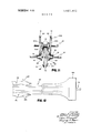
FIG. 2 is an end perspective view of the apparatus in FIG. 1 as seen from the downstream end;
FIG. 3 is the opposite end perspective view of the apparatus in FIG. 2;
FIG. 4 is a fragmentary perspective view similar to FIG. 2, but enlarged to show more details;
FIG. 5 is a fragmentary perspective view similar to FIG. 3, but enlarged to show more details;
FIG. 6 is a side perspective view of the apparatus in the previous figures;
FIGS. 7 and 8 are fragmentary perspective views taken from the opposite side as shown in FIG. 6, illustrating the alternate positions for the frame mounting the top axle subassembly;
FIG. 9 is a schematic view illustrating the path of the heating fluid for the apparatus;
FIG. 10 is a perspective view of the ing tunnel of the apparatus;
FIG. 11 is a fragmentary elevational view illustrating the relative positioning of the forming wheels of the device when engaging the web or sheet material; and
FIG. 12 is a schematic plan view illustrating use of the apparatus and the novel method.
preheating and preform- DESCRIPTION OF THE PREFERRED EMBODIMENT Referring now specifically to the drawings, apparatus 10 is for thermoforming a continuous web 20 of thermoplastic synthetic material such as foamed polystyrene, into a crop row cover 22 having a hat-shaped cross section, the thermoformed cover being designed to protect a row of crops 24 while spaced thereabove, yet being held in position by dirt 26 pushed over and onto the crop-straddling flanged edges of the cover (FIG. 12).
The apparatus (FIG. 1) includes a general framework 30 of a traveling vehicle of any suitable type, with at least two axles 32 and 34 joumaled thereto. A plurality of heated wheels or wheel- like members 40, 40a, 60, 60a, 70 and 70a constitute forming means, the wheels being mounted on axles 32 and 34. At least one of the axles is driven, as by a running wheel engaging the ground. The axle 34 is mounted above axle 32 and for reciprocation toward and away from axle 32 by means of a sub-frame 80 designed to allow its weight and the weight of axle 34 and its wheels to bias such down against the sheet material in cooperative relationship with the wheels on axle 32 thereunder.
A plurality of heating passageways is provided in the wheels and axles, communicant with a heat supply line 9 to feed hot fluid to these passageways (FIG. 9).
At various places in this specification, relative directions and positions such as peak, bottom, highest point," lower, and upper" are utilized. These are not absolute terms but are to be construed with respect to the orientation of the structure as described.
SHEET FEED The apparatus thermoforms a web continuously, such web preferably being fed from a roll of the sheet or web material mounted on a shaft 162 conventionally journaled to any convenient portion of frame 30 (FIG. 1).
PREFORMING AND PREHEATING TUNNEL Positioned downstream of roll 160 is a tunnel or inverted channel which receives the flat stock and curves it into a generally parabolic shape, convexly upward and concavely downward. Tunnel 170 (FIGS. 3, 4, 5, and 10) is positioned upstream of axles 32 and 34 and the forming wheels thereon, to assist in the feeding of the sheet between the wheels. The channel also has a preheating function (hereinafter described) which enables the web to be readily curved thereby and to partially prepare the material for the forming wheel The upstream end 172 of the channel is curved in cross section, with the tunnel converging to the hat-shaped downstream end 174 positioned adjacent the nip of the wheels. The peak 176 of the hat-shaped end 174 is aligned with the highest point of the primary wheels 40 on lower axle 32. The bottom edges 178 (FIG. 4) of channel 170 are aligned with the highest point of sleeve 70 of the secondary wheels 60 on lower axle 32. The web material is fed directly from tunnel 170 into the nip of the forming wheels.
FORMING WHEEL MEANS The two sets of forming wheels on the two axles are movable with respect to each other, together and apart. This is done by mounting one set on a movable frame portion and the other set on the fixed frame portion.
Turning now to FIGS. 2 through 5, and FIG. 11, frame 30 comprises a base 35, uprights 36, and a sub-frame 37 welded to base 35 and uprights 36. It is within sub-frame 37 that the axle 32 is journaled. The joumaling of the axles 32 and 34 is conventional, and accordingly is not further described.
On axle 32, a set of primary wheels 40 and secondary wheels 60 are mounted, wheels 40 being mounted between wheels 60, the latter being idler wheels. That is, wheels 40 are fixably mounted to axle 32, while wheels 60 are freely rotatably mounted, for purposes hereinafter described. The outer annular axial faces 62 of idler wheels 60 have a frustoconical surface (FIG. 11). The corresponding inside faces 64 of primary wheels 40 have a similar tapered surface.
Two wheel extension sleeves 70 are mounted immediately adjacent to and axially outside of idler wheels 60. Sleeves 70 are also freely rotatably mounted upon axle 32, for a reason hereinafter described.
The. second, upper axle 34 has a set of primary wheels 40a and secondary wheels 60a mounted thereon, the latter including wheel extension sleeves 70a. Primary wheels 40a are fixed to axle 34. Idler wheels 600 are rotatably mounted on the axle adjacent to and between primary wheels 40a. Idler wheels 600 have frustoconical, axially inner faces, cooperative with correspondingly tapered faces on the outer faces of the primary wheels mounted on axle 34. Sleeves 700 are combined into one freely rotatable sleeve between m idler rollers 60a.
Referring now to FIG. 11, the cooperation between the primary wheels and the idler wheels and sleeves will become apparent. Thus, primary wheels 40 cooperate with idler wheels 60a and sleeve 70a, while primary wheels 40a cooperate with idler wheels 60 and sleeve 70 to bend the sheet material into the hat-shaped cross section when the sheet feeds into the nip of the wheels. That is, surfaces 62 of the idler wheels and surfaces 64 of the primary wheels press on opposite sides of the sheet material while edges 72 of primary wheels 40a and 40 press the sheet material against the immediately adjacent sleeve 70 or 700, respectively, the opposite axle. Because the exterior diameter of the primary wheels is so much larger than the exterior diameter. of either of the cooperating idler wheel or sleeve, the interior diameter of the sleeve and of the idler wheel will rotate considerably faster than the axle on which the sleeve or idler wheel is mounted. Thus, as indicated above, the idler wheels and the sleeves are freely rotatably mounted on their axles.
The wheels and sleeves constitute bending surfaces, which, because of their rotation, are substantially free from friction due to slippage, as the wheels engage rather than slide against, the underside of the sheet material 20. Thus, the sheet material is not torn as it is fed through the bending wheels. This particularly important with respect to foam stock material.
To maintain the correct positioning of the idler wheels and the sleeves, spacing sleeves 74 and 74a are provided on the axles 32 and 34, respectively. The spacing sleeves can be fixed to the axles or freely rotated thereon.
ENGAGING MEANS FOR THE FORMING MEANS Referring now in FIGS. 6 through 8, axle 34 is journaled to sub-frame 80 at end 82 thereof, the opposite end 84 being pivotally mounted to sub-frame 37 on a shaft 85 journaled thereto (See FIG. 2). A U-bar 86 connects the ends 82 of the sub-frame, the U-bar extending over primary wheels 400. To raise and lower sub-frame 80 and axle 34 journaled thereto, a lever 90 is pivotally mounted at 91 on an upright 92 on sub frame 37. The lever has a connecting rod 96 pivoted thereto at a point 94 intermediate the ends of the lever. Connecting rod '96 comprises a threaded bar 98 and an adjustable connecting bar 100. The bar 98 is bolted to U-bar 86 at 102, so that when handle 90 is pivoted about its pivot 91, connecting link 96 causes U-bar 86 and sub-frame 80 to raise and lower with respect to sub-frame 37 and axle 34. As shown in FIG. 8, lever is released so as to lower sub-frame 80 and axle 32 into the engaging position for pressing against the sheet material to be thermoformed.
An upright is welded to sub-frame 37 and has positioned thereon a limiting bolt 112, the purpose of which is to limit the downward pivoting or reciprocation of sub-frame 80 on shaft 85.
DRIVE MEANS As indicated above, frame 30 normally is to be moved along the ground surface with vehicular means (not shown in detail) and driven as by wheel mounted on frame 30 (FIG. 1) by mount 31. The wheel 120 comprises a tire 122 fixably mounted to a spindle axle 124, journaled within a hub 126 attached to mount 31.
Thus, axles 32 and 34 are counter-rotatably driven,along with the primary wheels affixed thereto by wheel 120.
HEATING ample, when the sheet material is foamed polystyrene, the
heating fluid can be ethylene glycol. The fluid (FIG. 9) is supplied from a convenient heating source (not shown) to hose 190, a gauge 194 .indicating the temperature and/or pressure of the fluid.
From point 192 where hose 190 attaches to axle 32, the passageway of the heating fluid is through the center of axle 32 to a point near the middle of the length of the axle (See FIG. 9). At this point, the fluid is conducted througha tube 196 (FIG. 4) joined to axle 32 at a nipple 197 and extending radially out into the rim of one primary wheel 40 positioned adjacent tube 196. The tube 196 extends around in this primary wheel rim at least approximately once, at which point it emerges and merges with tube 198 which extends around the rim of the adjacent primary wheel (FIG. 2). Tube 198 coils.
around at least one, and extends radially back to axle 32 as tube 200 (FIG. 7). The heating fluid then flows outthe opposite end 202 of axle 32 to a line 204 which attaches to a passageway 206 mounted inside tunnel for the preheating function.
Passageway 206 (FIG. 10) is a tube similar to tubes 196, 198, and 200, previously described, but mounted within channel 170 on its interior surface. Tube 206 is bent to be positioned adjacent the portions of the channel having the greatest rate of curvature, thus delivering the heat to the portions of the sheet material which are to take on the greatest curvature. As will be readily apparent, these portions are the places where the bottom edge 178 of the channel joins the side p01- tions, and where the side portions of the channel join the top or peak portion 176.
After passing through tube 206, the heating fluid is then carried by line 210 to axle 34 at end 212 thereof (FIG. 9). The heating fluid is then carried down a passageway in axle 34 until it reaches a position exterior to the first primary wheel 404 on that axle, at which point a tube 214 is attached to the axle and carries the heating fluid therefrom to the circumference of primary wheel 40a. The tube 214 is wound around and within the circumference of the primary wheel 40a at least once, thereafter exiting through to the opposite side of the primary wheel to a nipple 216 where it joins axle 34 once again. The heating fluid then proceeds again through axle 34 to a nipple 218 which joins to tube 220 that extends to the rim of the second primary wheel 40a. The tube 220 winds around and within the circumference at least once, at which point it exits out the opposite side of the second primary wheel and joins once again to axle 34 at nipple 222. The heating fluid then exits out of axle 34 at end 224 and from there out a return line 228. All of the heating tubes described above are preferably formed from material of high heat conductivity, such as a copper alloy. It will be readily appreciated that because of the passageway of the heating fluid through the axle at the point where the idler wheels are positioned, the idler wheels also will be heated by the fluid. The flow of the heating fluid through the serially connected passageways causes transfer of heat to the sheet material as it passes through the wheels, to inelastically retain the hat-shaped cross section forced upon it by the cooperating nature of the bending wheels 40, 40a, 60, and 60a, and sleeves 70 and 70a.
METHOD The aforedescribed apparatus is utilized to thennoform thermoplastic sheet material continuously to produce in situ a continuous cover for dropping over rows of crops in fields. To this end, the roll 160 is unwound (FIG. 12) and fed continuously through tunnel and to the wheels 40, 40a, 60 and 60a causing a simultaneous heating and bending of the thermoplastic materials into the hat-shaped cross section desired for the cover. Thereafter, cover 22 so therrnoformed drops continuously over a row of crops as the apparatus moves along the row of crops. The flanged edges rest on the ground astraddle the row, while the self-supporting formed cover extends to a spaced position above the crop row. Plow means 230 can be attached to the frame or mounted on a separate apparatus to push earth up and over the flanged edges of the thennoformed cover, to retain the cover in place.
Conventional foamed polystyrene sheet is the preferred web stock material due to its resistance to weathering, its appropriate light transfer, and its self-supporting nature when so formed. Other thermoplastic material capable of being inelastically formed into a cross section similar to a hat-shape can be utilized in the apparatus and in accordance with the above-described method. Examples of such materials are foamed polyvinyl (PVC and/or PVA), non-foam polyvinyl, non-foam polystyrene, or any of several other thermoplastic materials well be known in the art.
The cross section of the formed member, as is shown, items a top panel joining a pair of side panels arranged in frustopyramidic fashion, with oppositely extending flanges at the lower edges of the side panels. The flanges are formed between the outer peripheral surfaces of primary wheels 40a and the peripheral surfaces of secondary sleeves 70.
OTHER EMBODIMENTS Although the invention has been described in connection with a preferred embodiment, it will be readily appreciated that many variations are possible which will provide an equivalent structure and method. For example, the primary wheels 40 can be combined into a single wheel on the axle 34 having a width which will span the same distance as presently spanned by the two wheels 40. Such a single wheel would require a heating tube around the circumference of both sides as is accomplished by having two separate wheels in the present disclosure. Still another modification could utilize wheels shaped so as to produce a hat-shaped cross section having varying dimensions or curved surfaces.
The apparatus can also be utilized to continuously produce thermoformed items having end uses other than a crop cover.
Accordingly, it is inten ed that the invention shall cover these additional equivalent structures and methods, unless the following claims expressly state otherwise.
The embodiments of the invention in which an exclusive property or privilege is claimed are defined as follows.
1. Apparatus for thermoforming a continuous web of material into a configurated structure, comprising: cooperative, rotational counter-rotating sets of forming wheels mounted on spaced axes; said wheels having similarly shaped, adjacent, cooperative, axially oriented forming surfaces thereon creating a continuous forming passage of generally hat-shaped configuration; and heating means to heat said surfaces.
2. The apparatus in claim 1 including preheating convergent tunnel means adjacent said wheels to receive flat stock and to initiate the structural formation therein.
3. The apparatus in claim 1 including two sets of wheels mounted on a pair of respective axles; means to counter-rotationally drive said axles; means for moving said axles and the wheels thereon toward and away from each other to shift them into and out of cooperative relationship; and said axially orienting surfaces being tapered.
4. The apparatus in claim 1 wherein said wheels include first larger diameter primary wheel means on one axis, cooperably arranged with first smaller diameter secondary wheel means on the second axis to form the top of the hat-shaped configuration, and a pair of second larger diameter primary wheel means on said second axis, astraddle of said first secondary wheel means, cooperably arranged with second smaller diameter secondary wheel means on said one axis.
5. The apparatus in claim 4 wherein said wheel means are mounted on axles on said axes, with either said primary wheel means or said secondary wheel means being rotationally fixed to said axles, and the other being freely rotatable thereon.
6. The apparatus in claim 1 including a convergent tunnel means having a web stock receiving end, and converging to a generally hat-shaped discharge end adjacent said wheels.
7. The apparatus in claim 6 including web stock heating means for said tunnel means.
8. The apparatus in claim 2 wherein said tunnel means also includes heating means.
9. The apparatus in claim 8 wherein said heating means includes hot fluid flow passages.
10. The thennoforming apparatus as defined in claim 3, wherein said driving means includes a wheel joumaled to move in engagement with the ground, and a drive train connected between said wheel and said axles.
11. Apparatus for continuously thennoforming continuous thermoplastic web stock into an elongated configurated crop cover, including bending means for bending the sheet material; bending surface means opposing said bending means and being especially adapted to contact one face of the web and to cooperate with said bending means to bend said web into a hat-shaped cross section, said surface means including wheel- ]ike members for engaging said one side of the web so as to substantially eliminate sliding friction between said surface means and the web; means for feeding said sheet to said bending means and said surface; and means for heating said bending means and said surface means, whereby the web is thermoforrned into said hat-shaped cross section as it is fed between said bending means and said surface means.
12. The thermoforming apparatus as defined in claim 11, wherein said heating means includes a passageway in each of said bending means and said surface, and means for supplying a hot fluid to said passageways.
Claims (12)
1. Apparatus for thermoforming a continuous web of material into a configurated structure, comprising: cooperative, rotational counter-rotating sets of forming wheels mounted on spaced axes; said wheels having similarly shaped, adjacent, cooperative, axially oriented forming surfaces thereon creating a continuous forming passage of generally hat-shaped configuration; and heating means to heat said surfaces.
2. The apparatus in claim 1 including preheating convergent tunnel means adjacent said wheels to receive flat stock and to initiate the structural formation therein.
3. The apparatus in claim 1 including two sets of wheels mounted on a pair of respective axles; means to counter-rotationally drive said axles; means for moving said axles and the wheels thereon toward and away from each other to shift them into and out of cooperative relationship; and said axially orienting surfaces being tapered.
4. The apparatus in claim 1 wherein said wheels include first larger diameter primary wheel means on one axis, cooperably arranged with first smaller diameter secondary wheel means on the second axis to form the top of the hat-shaped configuration, and a pair of second larger diameter primary wheel means on said second axis, astraddle of said first secondary wheel means, cooperably arranged with second smaller diameter secondary wheel means on said one axis.
5. The apparatus in claim 4 wherein said wheel means are mounted on axles on said axes, with either said primary wheel means or said secondary wheel means being rotationally fixed to said axles, and the other being freely rotatable thereon.
6. The apparatus in claim 1 including a convergent tunnel means having a web stock receiving end, and converging to a generally hat-shaped discharge end adjacent said wheels.
7. The apparatus in claim 6 including web stock heating means for said tunnel means.
8. The apparatus in claim 2 wherein said tunnel means also includes heating means.
9. The apparatus in claim 8 wherein said heating means includes hot fluid flow passages.
10. The thermoforming apparatus as defined in claim 3, wherein said driving means includes a wheel journaled to move in engagement with the ground, and a drive train connected between said wheel and said axles.
11. Apparatus for continuously thermoforming continuous thermoplastic web stock into an elongated Configurated crop cover, including bending means for bending the sheet material; bending surface means opposing said bending means and being especially adapted to contact one face of the web and to cooperate with said bending means to bend said web into a hat-shaped cross section, said surface means including wheel-like members for engaging said one side of the web so as to substantially eliminate sliding friction between said surface means and the web; means for feeding said sheet to said bending means and said surface; and means for heating said bending means and said surface means, whereby the web is thermoformed into said hat-shaped cross section as it is fed between said bending means and said surface means.
12. The thermoforming apparatus as defined in claim 11, wherein said heating means includes a passageway in each of said bending means and said surface, and means for supplying a hot fluid to said passageways.
Applications Claiming Priority (1)
| Application Number | Priority Date | Filing Date | Title |
|---|---|---|---|
| US1564870A | 1970-03-02 | 1970-03-02 |
Publications (1)
| Publication Number | Publication Date |
|---|---|
| US3661481A true US3661481A (en) | 1972-05-09 |
Family
ID=21772647
Family Applications (1)
| Application Number | Title | Priority Date | Filing Date |
|---|---|---|---|
| US15648A Expired - Lifetime US3661481A (en) | 1970-03-02 | 1970-03-02 | Mobile thermoforming apparatus |
Country Status (1)
| Country | Link |
|---|---|
| US (1) | US3661481A (en) |
Cited By (4)
| Publication number | Priority date | Publication date | Assignee | Title |
|---|---|---|---|---|
| US4186520A (en) * | 1978-05-30 | 1980-02-05 | The State Of Israel, Ministry Of Agriculture | Low level cultivation tunnels |
| US4220369A (en) * | 1978-08-21 | 1980-09-02 | Whitley James M | Foldable trunk-mountable camper |
| US4300797A (en) * | 1978-08-21 | 1981-11-17 | Whitley William N | Compactly foldable recreation enclosure |
| US4318514A (en) * | 1980-02-25 | 1982-03-09 | Wallace Weberg | Netting applicator |
Citations (7)
| Publication number | Priority date | Publication date | Assignee | Title |
|---|---|---|---|---|
| US1606271A (en) * | 1920-05-22 | 1926-11-09 | Herbert R Stratford | Method of making curved rubber strips |
| US1929903A (en) * | 1931-10-13 | 1933-10-10 | Walter R Schindler | Plant protector and method of making it |
| US2649888A (en) * | 1948-04-23 | 1953-08-25 | Armco Steel Corp | Mechanism for corrugating strips of material |
| GB714784A (en) * | 1952-02-01 | 1954-09-01 | Garden Plastics Ltd | Improvements to garden cloches |
| US2938566A (en) * | 1956-04-26 | 1960-05-31 | Ohio Commw Eng Co | Apparatus for forming solid structural members of glass fiber reinforced resin |
| GB891829A (en) * | 1960-04-05 | 1962-03-21 | Hermann Berstorff Maschb Ansta | Method of producing a continuous sheet of corrugated synthetic plastics material |
| US3156599A (en) * | 1960-09-07 | 1964-11-10 | Roland R Keesee | Method and apparatus for manufacturing cardboard molding |
-
1970
- 1970-03-02 US US15648A patent/US3661481A/en not_active Expired - Lifetime
Patent Citations (7)
| Publication number | Priority date | Publication date | Assignee | Title |
|---|---|---|---|---|
| US1606271A (en) * | 1920-05-22 | 1926-11-09 | Herbert R Stratford | Method of making curved rubber strips |
| US1929903A (en) * | 1931-10-13 | 1933-10-10 | Walter R Schindler | Plant protector and method of making it |
| US2649888A (en) * | 1948-04-23 | 1953-08-25 | Armco Steel Corp | Mechanism for corrugating strips of material |
| GB714784A (en) * | 1952-02-01 | 1954-09-01 | Garden Plastics Ltd | Improvements to garden cloches |
| US2938566A (en) * | 1956-04-26 | 1960-05-31 | Ohio Commw Eng Co | Apparatus for forming solid structural members of glass fiber reinforced resin |
| GB891829A (en) * | 1960-04-05 | 1962-03-21 | Hermann Berstorff Maschb Ansta | Method of producing a continuous sheet of corrugated synthetic plastics material |
| US3156599A (en) * | 1960-09-07 | 1964-11-10 | Roland R Keesee | Method and apparatus for manufacturing cardboard molding |
Cited By (4)
| Publication number | Priority date | Publication date | Assignee | Title |
|---|---|---|---|---|
| US4186520A (en) * | 1978-05-30 | 1980-02-05 | The State Of Israel, Ministry Of Agriculture | Low level cultivation tunnels |
| US4220369A (en) * | 1978-08-21 | 1980-09-02 | Whitley James M | Foldable trunk-mountable camper |
| US4300797A (en) * | 1978-08-21 | 1981-11-17 | Whitley William N | Compactly foldable recreation enclosure |
| US4318514A (en) * | 1980-02-25 | 1982-03-09 | Wallace Weberg | Netting applicator |
Similar Documents
| Publication | Publication Date | Title |
|---|---|---|
| US3734387A (en) | Tank fabrication system | |
| US3661481A (en) | Mobile thermoforming apparatus | |
| CN106586727A (en) | Automatic tube coiling machine convenient to mount and dismount | |
| EP0873846A3 (en) | Haul-off apparatus for plastic tubular films | |
| US3738059A (en) | Mobile thermoforming apparatus and method | |
| ATE125485T1 (en) | EXTRACTION DEVICE FOR PLASTIC FILM TUBES. | |
| CN110091530B (en) | Plastic steel winding pipe production line | |
| US6266862B1 (en) | Weld seam opening regulator for cylindrical tank building process | |
| CA1088284A (en) | Method and apparatus for flanging a length of spirally wound corrugated pipe | |
| US2159771A (en) | Sheet metal flanging apparatus | |
| US4319949A (en) | Machine for heat sealing polymeric sheets into a spiral drum | |
| CN213127358U (en) | Film covering device for agricultural planting | |
| US1899850A (en) | Pipe wrapping machine | |
| US1606123A (en) | Fabric-assembly table | |
| AU8084482A (en) | Irrigation ramp | |
| JPH0718278Y2 (en) | High density type cultivation device | |
| US3963194A (en) | Dispenser for coiled elongated flexible product | |
| CN116531703A (en) | Fire hose lays guiding mechanism | |
| CN109986843A (en) | A kind of production line and its production technology of adhesive tape paper tube | |
| US3449791A (en) | Irrigation pipe | |
| JPS61145027A (en) | Structure of curved part of belt conveyor | |
| CN211510340U (en) | Automatic medicine device that spouts in gardens | |
| KR100223957B1 (en) | Apparatus plastic pipe flange moulding | |
| CN216736264U (en) | Rim steel sheet conveying turning device for roll table | |
| CN212239964U (en) | Assembly line of butterfly valve |