US3649865A - Wire mesh member having intersecting strands bonded together and method of manufacture - Google Patents
Wire mesh member having intersecting strands bonded together and method of manufacture Download PDFInfo
- Publication number
- US3649865A US3649865A US888328A US3649865DA US3649865A US 3649865 A US3649865 A US 3649865A US 888328 A US888328 A US 888328A US 3649865D A US3649865D A US 3649865DA US 3649865 A US3649865 A US 3649865A
- Authority
- US
- United States
- Prior art keywords
- mesh
- strands
- mesh member
- metal
- wire
- Prior art date
- Legal status (The legal status is an assumption and is not a legal conclusion. Google has not performed a legal analysis and makes no representation as to the accuracy of the status listed.)
- Expired - Lifetime
Links
- 238000004519 manufacturing process Methods 0.000 title abstract description 11
- 238000000034 method Methods 0.000 title abstract description 11
- PXHVJJICTQNCMI-UHFFFAOYSA-N Nickel Chemical compound [Ni] PXHVJJICTQNCMI-UHFFFAOYSA-N 0.000 claims description 24
- 229910052751 metal Inorganic materials 0.000 claims description 20
- 239000002184 metal Substances 0.000 claims description 20
- 239000000463 material Substances 0.000 claims description 13
- 229910052759 nickel Inorganic materials 0.000 claims description 12
- 229910001220 stainless steel Inorganic materials 0.000 claims description 10
- 239000010935 stainless steel Substances 0.000 claims description 9
- RYGMFSIKBFXOCR-UHFFFAOYSA-N Copper Chemical compound [Cu] RYGMFSIKBFXOCR-UHFFFAOYSA-N 0.000 claims description 6
- 238000000576 coating method Methods 0.000 claims description 6
- 239000010949 copper Substances 0.000 claims description 6
- 229910052802 copper Inorganic materials 0.000 claims description 6
- BASFCYQUMIYNBI-UHFFFAOYSA-N platinum Chemical compound [Pt] BASFCYQUMIYNBI-UHFFFAOYSA-N 0.000 claims description 6
- 239000011248 coating agent Substances 0.000 claims description 5
- BQCADISMDOOEFD-UHFFFAOYSA-N Silver Chemical compound [Ag] BQCADISMDOOEFD-UHFFFAOYSA-N 0.000 claims description 3
- 229910052697 platinum Inorganic materials 0.000 claims description 3
- 229910052709 silver Inorganic materials 0.000 claims description 3
- 239000004332 silver Substances 0.000 claims description 3
- WFKWXMTUELFFGS-UHFFFAOYSA-N tungsten Chemical compound [W] WFKWXMTUELFFGS-UHFFFAOYSA-N 0.000 claims description 3
- 239000010937 tungsten Substances 0.000 claims description 3
- 229910052721 tungsten Inorganic materials 0.000 claims description 3
- 230000005540 biological transmission Effects 0.000 abstract description 14
- 238000009713 electroplating Methods 0.000 abstract description 12
- 238000007747 plating Methods 0.000 abstract description 7
- 238000005530 etching Methods 0.000 abstract description 6
- 238000003860 storage Methods 0.000 abstract description 6
- 238000010894 electron beam technology Methods 0.000 abstract description 2
- PEDCQBHIVMGVHV-UHFFFAOYSA-N Glycerine Chemical compound OCC(O)CO PEDCQBHIVMGVHV-UHFFFAOYSA-N 0.000 description 2
- NBIIXXVUZAFLBC-UHFFFAOYSA-N Phosphoric acid Chemical compound OP(O)(O)=O NBIIXXVUZAFLBC-UHFFFAOYSA-N 0.000 description 2
- 238000010586 diagram Methods 0.000 description 2
- 238000005498 polishing Methods 0.000 description 2
- 229910000906 Bronze Inorganic materials 0.000 description 1
- 229910021586 Nickel(II) chloride Inorganic materials 0.000 description 1
- 235000007889 Osmunda cinnamomea Nutrition 0.000 description 1
- OAICVXFJPJFONN-UHFFFAOYSA-N Phosphorus Chemical compound [P] OAICVXFJPJFONN-UHFFFAOYSA-N 0.000 description 1
- 244000239204 Plantago lanceolata Species 0.000 description 1
- 235000010503 Plantago lanceolata Nutrition 0.000 description 1
- 229910045601 alloy Inorganic materials 0.000 description 1
- 239000000956 alloy Substances 0.000 description 1
- 229910000147 aluminium phosphate Inorganic materials 0.000 description 1
- KGBXLFKZBHKPEV-UHFFFAOYSA-N boric acid Chemical compound OB(O)O KGBXLFKZBHKPEV-UHFFFAOYSA-N 0.000 description 1
- 239000004327 boric acid Substances 0.000 description 1
- 239000010974 bronze Substances 0.000 description 1
- 238000003486 chemical etching Methods 0.000 description 1
- 238000001816 cooling Methods 0.000 description 1
- KUNSUQLRTQLHQQ-UHFFFAOYSA-N copper tin Chemical compound [Cu].[Sn] KUNSUQLRTQLHQQ-UHFFFAOYSA-N 0.000 description 1
- 238000005868 electrolysis reaction Methods 0.000 description 1
- 235000011187 glycerol Nutrition 0.000 description 1
- 239000007788 liquid Substances 0.000 description 1
- 150000002739 metals Chemical class 0.000 description 1
- QMMRZOWCJAIUJA-UHFFFAOYSA-L nickel dichloride Chemical compound Cl[Ni]Cl QMMRZOWCJAIUJA-UHFFFAOYSA-L 0.000 description 1
- LGQLOGILCSXPEA-UHFFFAOYSA-L nickel sulfate Chemical compound [Ni+2].[O-]S([O-])(=O)=O LGQLOGILCSXPEA-UHFFFAOYSA-L 0.000 description 1
- 229910000363 nickel(II) sulfate Inorganic materials 0.000 description 1
- 239000000126 substance Substances 0.000 description 1
- 238000007740 vapor deposition Methods 0.000 description 1
- XLYOFNOQVPJJNP-UHFFFAOYSA-N water Substances O XLYOFNOQVPJJNP-UHFFFAOYSA-N 0.000 description 1
- 238000003466 welding Methods 0.000 description 1
Images
Classifications
-
- H—ELECTRICITY
- H01—ELECTRIC ELEMENTS
- H01J—ELECTRIC DISCHARGE TUBES OR DISCHARGE LAMPS
- H01J9/00—Apparatus or processes specially adapted for the manufacture, installation, removal, maintenance of electric discharge tubes, discharge lamps, or parts thereof; Recovery of material from discharge tubes or lamps
- H01J9/02—Manufacture of electrodes or electrode systems
- H01J9/14—Manufacture of electrodes or electrode systems of non-emitting electrodes
-
- H—ELECTRICITY
- H01—ELECTRIC ELEMENTS
- H01J—ELECTRIC DISCHARGE TUBES OR DISCHARGE LAMPS
- H01J19/00—Details of vacuum tubes of the types covered by group H01J21/00
- H01J19/28—Non-electron-emitting electrodes; Screens
- H01J19/38—Control electrodes, e.g. grid
-
- H—ELECTRICITY
- H01—ELECTRIC ELEMENTS
- H01J—ELECTRIC DISCHARGE TUBES OR DISCHARGE LAMPS
- H01J2893/00—Discharge tubes and lamps
- H01J2893/0001—Electrodes and electrode systems suitable for discharge tubes or lamps
- H01J2893/0012—Constructional arrangements
- H01J2893/0015—Non-sealed electrodes
- H01J2893/0016—Planar grids
Definitions
- the bonded mesh member is etched by electropolishing to unifonnly reduce the diameter of the wires and removes the plating layer from the wires except in the regions of such bonds. This electropolishing increases the electron transmission characteristics of the wire mesh, in one example to a transmission of 85 to 90 percent.
- a mesh member may be used as a grid, a collector or a storage target electrode in an electron beam tube.
- the subject matter of the present invention relates generally to wire mesh members of high transmission characteristics and methods of manufacture thereof, and in particular, to such meshes having their intersecting wire strands bonded together at the intersections, such as by electroplating, and subsequently etched, such as by electropolishing, to uniformly reduce the diameter of the wires and remove the plating except in the regions of the bonds.
- wire mesh members of the present invention are especially useful as electrodes in electron tubes because of their high electron transmission characteristics as well as their strength and dimensional stability due to such bonding.
- such mesh electrodes can be employed as control grids of electron guns, collector meshes or storage target meshes for storage tubes, as well as the high-frequency interference shields.
- Another object of the invention is to provide such mesh member and method of manufacture in which the bonding is achieved by electroplating the mesh, and the bonded mesh is etched to reduce the diameter of the wires and remove the plating except in the region of the bonds.
- a further object of the present invention is to provide such a mesh member and method of manufacture in which the etching is accomplished by electropolishing to more uniformly remove material from the mesh strands and provide the desired wire diameter with a high degree of accuracy.
- An additional object of the invention is to provide an improved electron transmission electrode for an electron tube employing the mesh member of the present invention.
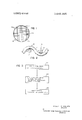
- FIG. I is an elevation view of the wire mesh member made in accordance with the present invention.
- FIG. 2 is a horizontal section view taken along the line 2-2 of FIG. 1 showing on an enlarged scale the bonds at the intersections of the mesh strands;
- FIG. 3 is a block diagram illustrating one embodiment of the method of manufacture of the present invention which can be employed to form the mesh member of FIGS. 1 and 2.
- a mesh member 10 made in accordance with the present invention includes a plurality of first wire strands l2 laterally spaced from each other and extending substantially parallel in a first direction, and a plurality of second wire strands l4 laterally spaced from each other and extending substantially parallel in a second direction.
- the strands l2 and 14 are substantially perpendicular so that the second direction is displaced approximately from such first direction.
- the first and second strands are interwoven so that they intersect each other forming a plurality of intersections 16 where the first strands cross the second strands.
- a plurality of bonds 18 are formed at each of the intersections 16 out of a bonding material other than the material of the wires which is provided between the first strands l2 and the second strands 14.
- the wire strands l2 and 14 may be made of stainless steel while the bonds 18 are made of nickel.
- the wire mesh may be attached to a mounting ring 20 of stainless steel, nickel or other suitable metal, in a conventional manner, such as by welding. After etching to increase transparency of the mesh, the bonding material 18 is confined solely to the region of the bonds at the intersections l6 and does not coat other portions of the wire strands 12.
- the mesh member 10 is an extremely strong, stable mesh member of high transparency to electrons, light, gas, liquid, etc.
- the mesh member of FIG. 1 may be employed as the control grid of an electron gun employed in a conventional cathode-ray tube, and as a collector electrode or as a meshtype storage target electrode in a charge image storage tube.
- Other uses for the mesh member include an electrostatic shield against the high-frequency interference, for example, covering the air cooling opening for the fan at the rear of a cathode-ray oscilloscope.
- one embodiment of the method of manufacture of the present invention includes the three steps illustrated by boxes 22, 24 and 26, which respectively relate to first, providing a woven wire mesh, second, electroplating the mesh sufficiently to form a coating that joins the cross strands of the mesh together with chemical bonds at their intersections, and third, electroetch polishing of the bonded mesh to reduce the diameter of the wires and remove the plating from such wires except in the region of the bonds.
- electropolishing refers to etching by electrolysis, In one example, a stainless steel wire mesh was provided in step 22 having wire strands of 0,001 inch diameter which were woven together to provide a mesh of lines per inch.
- this woven wire mesh member was then placed in a nickel electroplating solution of 20 grams per liter of nickel sulfate, 45 grams per liter of nickel chloride, and 30 grams per liter of boric acid, at a pH factor of 2.3 to 4.5 and a temperature of 43 centigrade. Electroplating is continued at a current density of 0.02 to 0.07 amperes per square centimeter for 30 to 60 minutes, until a coating of about 0.0002 inch of nickel is formed on the wire strands of the mesh, which is sufficient to bond the strands together at their intersections.
- the bonded mesh was etched in accordance with step 26 in an electropolishing solution of 300 milliliters phosphoric acid, 530 milliliters of glycerine, and 90 milliliters of water.
- a stainless steel cathode was employed in the electropolishing step and a current density of 0.12 amperes per square centimeter flowed for about 2 hours to reduce the diameter of the wire strands to about one fourth of their original dimension, thereby removing all of the electroplating except that forming the bonds l8.
- a mesh member made in accordance with the above example has an electron transmission characteristic of about 85 to 90 percent, which represents an increase over that of a conventional unbonded wire mesh.
- the mesh member of the present invention in spite of bonding the intersecting wire strands to provide a much stronger and more stable mesh, is still more electron transparent than a conventional unbonded mesh.
- the wire mesh can be copper, nickel, tungsten, or alloys such as phosphor bronze.
- the electroplated bonding material can be a metal other than nickel, such as copper, platinum or silver.
- other coating methods than electroplating such as vapor deposition, can be used to form the bonds.
- chemical etching other than electropolishing can be used for removal of the excess bonding material, but electropolishing is preferred because it is extremely accurate and produces smooth wires of substantially uniform diameter.
- the mesh may be made of a different weave or with wires of noncircular cross section, including strands of rectangular or square cross section. Therefore, the scope of the present invention should only be determined by the following claims.
- a mesh electrode member comprising:
- first metal strands laterally spaced from each other and extending in a first direction
- bonding means including a plurality of bonds formed between intersecting portions of said first and second strands by bonding material provided as a coating on said strands only at said bonds, said first and second strands being uncoated by said bonding material except at said intersecting portions.
- a mesh member in accordance with claim I in which the mesh is made of wire of substantially circular cross section and which includes support means for mounting said mesh member in an electron tube.
- a mesh member in accordance with claim I in which the strand metal is taken from a first group consisting of stainless steel, copper, nickel and tungsten, and the bonding metal is taken from a second group consisting of nickel, copper, silver and platinum.
Landscapes
- Engineering & Computer Science (AREA)
- Manufacturing & Machinery (AREA)
- Wire Processing (AREA)
- Electroplating Methods And Accessories (AREA)
Abstract
A woven wire mesh member and method of manufacture are described in which the intersecting wire strands are bonded together and then etched for increasing the transmission characteristics of such mesh. The bonding of the intersecting portions of the wire strands is accomplished by electroplating and insures a strong mesh structure whose wires remain in a fixed position after such etching. The bonded mesh member is etched by electropolishing to uniformly reduce the diameter of the wires and removes the plating layer from the wires except in the regions of such bonds. This electropolishing increases the electron transmission characteristics of the wire mesh, in one example to a transmission of 85 to 90 percent. Such a mesh member may be used as a grid, a collector or a storage target electrode in an electron beam tube.
Description
United States Patent Holmes [54] WIRE MESH MEMBER HAVING INTERSECTING STRANDS BONDED TOGETHER AND METHOD OF MANUFACTURE [72] Inventor: Robert E. Holmes, Portland, Oreg.
[73] Assignee: Tektronix, lnc., Tektronix Industrial Park,
Beaverton, Oreg.
[22] Filed: Dec. 29, 1969 [21] Appl. No.: 888,328
[52] US. Cl ..3l3/350, 204/16, 204/24,
313/293 [51] lnt.Cl ..H01j1/46,H01j 1/52,H0lj 17/04 [58] Field ofSearch ..3l3/293, 350; 204/16, 24
[56] References Cited UNITED STATES PATENTS Re22,009 l/l942 Farnsworth ..3l3/350X 5] Mar. 14, 1972 1,892,819 l/l933 Gessel ..313/350 Primary ExaminerDavid Schonberg Assistant Examiner-Paul A. Sacher Attorney-Buckhom, Blore, Klarquist and Sparkman ABSTRACT A woven wire mesh member and method of manufacture are described in which the intersecting wire strands are bonded together and then etched for increasing the transmission characteristics of such mesh. The bonding of the intersecting portions of the wire strands is accomplished by electroplating and insures a strong mesh structure whose wires remain in a fixed position after such etching. The bonded mesh member is etched by electropolishing to unifonnly reduce the diameter of the wires and removes the plating layer from the wires except in the regions of such bonds. This electropolishing increases the electron transmission characteristics of the wire mesh, in one example to a transmission of 85 to 90 percent. Such a mesh member may be used as a grid, a collector or a storage target electrode in an electron beam tube.
6 Claims, 3 Drawing Figures PATENTEBMAR 14 1972 as. I
FIG. 3
WOVEN WIRE MESH 1e. STAINLESS STEEL) ELECTRO-PLATE MESH TO FORM COATING (l6 NICKLEJ THAT BONDS CROSS STRANDS ELECTRO-ETCH POLISHING OF COATED MESH ROBERT E. HOLMES INVENTOR BY BUCKHORN, BLORE, KLARQUIST & SPARKMAN ATTORNEYS WIRE MESH MEMBER HAVING INTERSECTING STRANDS BONDED TOGETHER AND METHOD OF MANUFACTURE BACKGROUND OF THE INVENTION The subject matter of the present invention relates generally to wire mesh members of high transmission characteristics and methods of manufacture thereof, and in particular, to such meshes having their intersecting wire strands bonded together at the intersections, such as by electroplating, and subsequently etched, such as by electropolishing, to uniformly reduce the diameter of the wires and remove the plating except in the regions of the bonds. The wire mesh members of the present invention are especially useful as electrodes in electron tubes because of their high electron transmission characteristics as well as their strength and dimensional stability due to such bonding. Specifically, such mesh electrodes can be employed as control grids of electron guns, collector meshes or storage target meshes for storage tubes, as well as the high-frequency interference shields.
It has previously been proposed to electroplate wire mesh members for various reasons. U.S. Pat. No. 1,934,643 of HR. Rafton, issued Nov. 7, 1933, shows a straining filter made by electroplating a wire mesh sufficiently to cause the intersecting strands of the mesh to be bonded together and thereby providing a fine mesh filter. However, such meshes are entirely unsuitable for many uses, such as electrodes in electron tubes, because of the great reduction in electron transmission caused by such electroplating, U.S. Pat. No. 2,978,389 of AA. Turnbull shows a wire mesh electrode which is electroplated to place the mesh in tension but apparently the plating is not of sufficient thickness to cause such bonding. In any case, it has never previously been proposed to produce a bonded, high transmission wire mesh like that of the present invention by bonding the intersecting wires, such as by electroplating, before etching to reduce the diameter of the wires, such as by electropolishing, so that the plating is removed except in the regions of the bonds. This bonding overcomes the problems of lack of strength and looseness of the wire strands resulting in a nonuniform mesh, which are caused when an unbonded wire mesh is etched.
It is therefore one object of the present invention to provide a high transmission, woven wire mesh member and method of manufacture in which the intersecting metal wire strands of the mesh are bonded together at such intersections prior to removal of material from the wire for increased transmission in order to provide such mesh member with greater strength and with strands of fixed relative positions.
Another object of the invention is to provide such mesh member and method of manufacture in which the bonding is achieved by electroplating the mesh, and the bonded mesh is etched to reduce the diameter of the wires and remove the plating except in the region of the bonds.
A further object of the present invention is to provide such a mesh member and method of manufacture in which the etching is accomplished by electropolishing to more uniformly remove material from the mesh strands and provide the desired wire diameter with a high degree of accuracy.
An additional object of the invention is to provide an improved electron transmission electrode for an electron tube employing the mesh member of the present invention.
BRIEF DESCRIPTION OF THE DRAWINGS Other objects and advantages of the present invention will be apparent from the following detailed description of a preferred embodiment thereof and from the attached drawings of which:
FIG. I is an elevation view of the wire mesh member made in accordance with the present invention;
FIG. 2 is a horizontal section view taken along the line 2-2 of FIG. 1 showing on an enlarged scale the bonds at the intersections of the mesh strands; and
FIG. 3 is a block diagram illustrating one embodiment of the method of manufacture of the present invention which can be employed to form the mesh member of FIGS. 1 and 2.
DESCRIPTION OF THE PREFERRED EMBODIMENT As shown in FIG. 1, a mesh member 10 made in accordance with the present invention includes a plurality of first wire strands l2 laterally spaced from each other and extending substantially parallel in a first direction, and a plurality of second wire strands l4 laterally spaced from each other and extending substantially parallel in a second direction. In the embodiment shown, the strands l2 and 14 are substantially perpendicular so that the second direction is displaced approximately from such first direction. The first and second strands are interwoven so that they intersect each other forming a plurality of intersections 16 where the first strands cross the second strands.
A plurality of bonds 18 are formed at each of the intersections 16 out of a bonding material other than the material of the wires which is provided between the first strands l2 and the second strands 14. For example, in one embodiment, the wire strands l2 and 14 may be made of stainless steel while the bonds 18 are made of nickel. The wire mesh may be attached to a mounting ring 20 of stainless steel, nickel or other suitable metal, in a conventional manner, such as by welding. After etching to increase transparency of the mesh, the bonding material 18 is confined solely to the region of the bonds at the intersections l6 and does not coat other portions of the wire strands 12. As a result, the mesh member 10 is an extremely strong, stable mesh member of high transparency to electrons, light, gas, liquid, etc.
The mesh member of FIG. 1 may be employed as the control grid of an electron gun employed in a conventional cathode-ray tube, and as a collector electrode or as a meshtype storage target electrode in a charge image storage tube. Other uses for the mesh member include an electrostatic shield against the high-frequency interference, for example, covering the air cooling opening for the fan at the rear of a cathode-ray oscilloscope.
As shown in the simplified flow diagram of FIG. 3, one embodiment of the method of manufacture of the present invention includes the three steps illustrated by boxes 22, 24 and 26, which respectively relate to first, providing a woven wire mesh, second, electroplating the mesh sufficiently to form a coating that joins the cross strands of the mesh together with chemical bonds at their intersections, and third, electroetch polishing of the bonded mesh to reduce the diameter of the wires and remove the plating from such wires except in the region of the bonds. The term electropolishing as used herein refers to etching by electrolysis, In one example, a stainless steel wire mesh was provided in step 22 having wire strands of 0,001 inch diameter which were woven together to provide a mesh of lines per inch. In accordance with step 24, this woven wire mesh member was then placed in a nickel electroplating solution of 20 grams per liter of nickel sulfate, 45 grams per liter of nickel chloride, and 30 grams per liter of boric acid, at a pH factor of 2.3 to 4.5 and a temperature of 43 centigrade. Electroplating is continued at a current density of 0.02 to 0.07 amperes per square centimeter for 30 to 60 minutes, until a coating of about 0.0002 inch of nickel is formed on the wire strands of the mesh, which is sufficient to bond the strands together at their intersections. Then, the bonded mesh was etched in accordance with step 26 in an electropolishing solution of 300 milliliters phosphoric acid, 530 milliliters of glycerine, and 90 milliliters of water. A stainless steel cathode was employed in the electropolishing step and a current density of 0.12 amperes per square centimeter flowed for about 2 hours to reduce the diameter of the wire strands to about one fourth of their original dimension, thereby removing all of the electroplating except that forming the bonds l8.
A mesh member made in accordance with the above example has an electron transmission characteristic of about 85 to 90 percent, which represents an increase over that of a conventional unbonded wire mesh. Thus, the mesh member of the present invention, in spite of bonding the intersecting wire strands to provide a much stronger and more stable mesh, is still more electron transparent than a conventional unbonded mesh.
Of course, other metals than stainless steel can be employed for the wire mesh, such as copper, nickel, tungsten, or alloys such as phosphor bronze. Likewise, the electroplated bonding material can be a metal other than nickel, such as copper, platinum or silver. For some applications, other coating methods than electroplating, such as vapor deposition, can be used to form the bonds. Also, chemical etching other than electropolishing can be used for removal of the excess bonding material, but electropolishing is preferred because it is extremely accurate and produces smooth wires of substantially uniform diameter.
it will be obvious to those having ordinary skill in the art that many changes may be made in the details of the abovedescribed preferred embodiment of the present invention. For example, the mesh may be made of a different weave or with wires of noncircular cross section, including strands of rectangular or square cross section. Therefore, the scope of the present invention should only be determined by the following claims.
I claim:
1. A mesh electrode member, comprising:
a plurality of first metal strands laterally spaced from each other and extending in a first direction;
a plurality of second metal strands laterally spaced from each other and extending in a second direction across said first strands, said first and second strands being interwoven to form a mesh and having intersecting portions which cross other strands; and
bonding means including a plurality of bonds formed between intersecting portions of said first and second strands by bonding material provided as a coating on said strands only at said bonds, said first and second strands being uncoated by said bonding material except at said intersecting portions.
2. A mesh member in accordance with claim 1 in which the mesh is attached to a support ring surrounding said mesh.
3. A mesh member in accordance with claim I in which the mesh is made of wire of substantially circular cross section and which includes support means for mounting said mesh member in an electron tube.
4. A mesh member in accordance with claim 1 in which the bonding material is a metal difierent than the metal of said first and second strands.
5. A mesh member in accordance with claim 4 in which the bonding metal is nickel and the strand metal is stainless steel.
6. A mesh member in accordance with claim I in which the strand metal is taken from a first group consisting of stainless steel, copper, nickel and tungsten, and the bonding metal is taken from a second group consisting of nickel, copper, silver and platinum.
Claims (6)
1. A mesh electrode member, comprising: a plurality of first metal strands laterally spaced from each other and extending in a first direction; a plurality of second metal strands laterally spaced from each other and extending in a second direction across said first strands, said first and second strands being interwoven to form a mesh and having intersecting portions which cross other strands; and bonding means including a plurality of bonds formed between intersecting portions of said first and second strands by bonding material provided as a coating on said strands only at said bonds, said first and second strands being uncoated by said bonding material except at said intersecting portions.
2. A mesh member in accordance with claim 1 in which the mesh is attached to a support ring surrounding said mesh.
3. A mesh member in accordance with claim 1 in which the mesh is made of wire of substantially circular cross section and which includes support means for mounting said mesh member in an electron tube.
4. A mesh member in accordance with claim 1 in which the bonding material is a metal different than the metal of said first and second strands.
5. A mesh member in accordance with claim 4 in which the bonding metal is nickel and the strand metal is stainless steel.
6. A mesh member in accordance with claim 1 in which the strand metal is taken from a first group consisting of stainless steel, copper, nickel and tungsten, and the bonding metal is taken from a second group consisting of nickel, copper, silver and platinum.
Applications Claiming Priority (1)
| Application Number | Priority Date | Filing Date | Title |
|---|---|---|---|
| US88832869A | 1969-12-29 | 1969-12-29 |
Publications (1)
| Publication Number | Publication Date |
|---|---|
| US3649865A true US3649865A (en) | 1972-03-14 |
Family
ID=25392981
Family Applications (1)
| Application Number | Title | Priority Date | Filing Date |
|---|---|---|---|
| US888328A Expired - Lifetime US3649865A (en) | 1969-12-29 | 1969-12-29 | Wire mesh member having intersecting strands bonded together and method of manufacture |
Country Status (1)
| Country | Link |
|---|---|
| US (1) | US3649865A (en) |
Cited By (9)
| Publication number | Priority date | Publication date | Assignee | Title |
|---|---|---|---|---|
| US3892612A (en) * | 1971-07-02 | 1975-07-01 | Gen Electric | Method for fabricating foreign object damage protection for rotar blades |
| US4421609A (en) * | 1979-07-16 | 1983-12-20 | Compagnie Generale Des Etablissements Michelin | Process for producing electrode with current outlets |
| US4518661A (en) * | 1982-09-28 | 1985-05-21 | Rippere Ralph E | Consolidation of wires by chemical deposition and products resulting therefrom |
| US5449273A (en) * | 1994-03-21 | 1995-09-12 | United Technologies Corporation | Composite airfoil leading edge protection |
| US5700363A (en) * | 1996-02-15 | 1997-12-23 | Inco Limited | Porous nickel electrode substrate |
| US20090255816A1 (en) * | 2006-05-16 | 2009-10-15 | Aibel As | Electrostatic coalescing device |
| US20100000868A1 (en) * | 2006-05-16 | 2010-01-07 | Aibel As | Method for fabricating a sheet-shaped electrode and a sheet-shaped electrode for an electrostatic coalescing device |
| US8328073B1 (en) | 2008-02-07 | 2012-12-11 | Standard Chain Co. | Ornamented metallic mesh and method of making same |
| US11076514B1 (en) * | 2016-10-04 | 2021-07-27 | Triton Systems, Inc. | Metalized fiber mat |
Citations (2)
| Publication number | Priority date | Publication date | Assignee | Title |
|---|---|---|---|---|
| US22009A (en) * | 1858-11-09 | Apparatus for wetting paper | ||
| US1892819A (en) * | 1929-04-27 | 1933-01-03 | Philips Nv | Method of soldering together metal parts |
-
1969
- 1969-12-29 US US888328A patent/US3649865A/en not_active Expired - Lifetime
Patent Citations (2)
| Publication number | Priority date | Publication date | Assignee | Title |
|---|---|---|---|---|
| US22009A (en) * | 1858-11-09 | Apparatus for wetting paper | ||
| US1892819A (en) * | 1929-04-27 | 1933-01-03 | Philips Nv | Method of soldering together metal parts |
Cited By (12)
| Publication number | Priority date | Publication date | Assignee | Title |
|---|---|---|---|---|
| US3892612A (en) * | 1971-07-02 | 1975-07-01 | Gen Electric | Method for fabricating foreign object damage protection for rotar blades |
| US4421609A (en) * | 1979-07-16 | 1983-12-20 | Compagnie Generale Des Etablissements Michelin | Process for producing electrode with current outlets |
| US4518661A (en) * | 1982-09-28 | 1985-05-21 | Rippere Ralph E | Consolidation of wires by chemical deposition and products resulting therefrom |
| US5449273A (en) * | 1994-03-21 | 1995-09-12 | United Technologies Corporation | Composite airfoil leading edge protection |
| US5700363A (en) * | 1996-02-15 | 1997-12-23 | Inco Limited | Porous nickel electrode substrate |
| US20090255816A1 (en) * | 2006-05-16 | 2009-10-15 | Aibel As | Electrostatic coalescing device |
| US20100000868A1 (en) * | 2006-05-16 | 2010-01-07 | Aibel As | Method for fabricating a sheet-shaped electrode and a sheet-shaped electrode for an electrostatic coalescing device |
| US8282804B2 (en) * | 2006-05-16 | 2012-10-09 | Hamworthy Plc | Electrostatic coalescing device |
| US8349153B2 (en) * | 2006-05-16 | 2013-01-08 | Hamworthy Plc | Method for fabricating a sheet-shaped electrode and a sheet-shaped electrode for an electrostatic coalescing device |
| US8328073B1 (en) | 2008-02-07 | 2012-12-11 | Standard Chain Co. | Ornamented metallic mesh and method of making same |
| US11076514B1 (en) * | 2016-10-04 | 2021-07-27 | Triton Systems, Inc. | Metalized fiber mat |
| US11884827B1 (en) | 2016-10-04 | 2024-01-30 | Triton Systems, Inc | Nickel free conductive filler |
Similar Documents
| Publication | Publication Date | Title |
|---|---|---|
| US3649865A (en) | Wire mesh member having intersecting strands bonded together and method of manufacture | |
| DE1055584B (en) | Vidicon-type television pick-up tubes and method of making them | |
| US3484645A (en) | Non-intercepting grid structure for an electron tube | |
| EP0780871A1 (en) | Structured surface with pointed elements | |
| GB406353A (en) | Improvements in or relating to cathode ray tubes and the like | |
| FI66262C (en) | KATODSTRAOLEROER | |
| US2793178A (en) | Method of providing insulator with multiplicity of conducting elements | |
| US2047369A (en) | Photoelectric device | |
| US2115855A (en) | Cathode ray tube | |
| US3748514A (en) | Multi-beam cathode ray tube character display | |
| DE704365C (en) | Electron beam tubes for television | |
| DE2128921A1 (en) | Apparatus comprising a high vacuum electric discharge tube with at least two non-emission electrodes and a discharge tube for use in such a device | |
| US3597822A (en) | Method of making filamentary metal structures | |
| US3311964A (en) | Method of manufacturing a frame grid | |
| US3523347A (en) | Method of fabricating a nonintercepting grid assembly for an electron tube | |
| JPH0869749A (en) | Preparation of microchip electron source | |
| US4567399A (en) | Cathode ray tube with spherical aberration correction means | |
| JPS6150155B2 (en) | ||
| US3141988A (en) | Electron-gun using combined magnetic and electrostatic focussing | |
| CA1073517A (en) | Method of manufacturing a colour display tube with postfocusing electrode and a tube made by said method | |
| US3802855A (en) | Method of and apparatus for supporting cathode heaters | |
| US3772561A (en) | Electron discharge device grid having enhanced thermal conductivity and reduced secondary emission characteristics | |
| US4684994A (en) | Television camera tube with honeycomb grid electrode | |
| JPS59221960A (en) | Photomultiplier tube employing meshed dynode | |
| US2962429A (en) | Method of making electronic tube grid |