US364983A - Feedeeick altman - Google Patents
Feedeeick altman Download PDFInfo
- Publication number
- US364983A US364983A US364983DA US364983A US 364983 A US364983 A US 364983A US 364983D A US364983D A US 364983DA US 364983 A US364983 A US 364983A
- Authority
- US
- United States
- Prior art keywords
- vane
- altman
- collar
- rod
- pump
- Prior art date
- Legal status (The legal status is an assumption and is not a legal conclusion. Google has not performed a legal analysis and makes no representation as to the accuracy of the status listed.)
- Expired - Lifetime
Links
- 238000012856 packing Methods 0.000 description 3
- 238000010276 construction Methods 0.000 description 2
- 230000006872 improvement Effects 0.000 description 2
- 244000286663 Ficus elastica Species 0.000 description 1
- RRHGJUQNOFWUDK-UHFFFAOYSA-N Isoprene Chemical compound CC(=C)C=C RRHGJUQNOFWUDK-UHFFFAOYSA-N 0.000 description 1
- 239000000314 lubricant Substances 0.000 description 1
- 229920001195 polyisoprene Polymers 0.000 description 1
- 230000035939 shock Effects 0.000 description 1
- 239000002023 wood Substances 0.000 description 1
Images
Classifications
-
- F—MECHANICAL ENGINEERING; LIGHTING; HEATING; WEAPONS; BLASTING
- F03—MACHINES OR ENGINES FOR LIQUIDS; WIND, SPRING, OR WEIGHT MOTORS; PRODUCING MECHANICAL POWER OR A REACTIVE PROPULSIVE THRUST, NOT OTHERWISE PROVIDED FOR
- F03D—WIND MOTORS
- F03D7/00—Controlling wind motors
- F03D7/02—Controlling wind motors the wind motors having rotation axis substantially parallel to the air flow entering the rotor
- F03D7/0204—Controlling wind motors the wind motors having rotation axis substantially parallel to the air flow entering the rotor for orientation in relation to wind direction
- F03D7/0208—Orientating out of wind
- F03D7/0212—Orientating out of wind the rotating axis remaining horizontal
-
- Y—GENERAL TAGGING OF NEW TECHNOLOGICAL DEVELOPMENTS; GENERAL TAGGING OF CROSS-SECTIONAL TECHNOLOGIES SPANNING OVER SEVERAL SECTIONS OF THE IPC; TECHNICAL SUBJECTS COVERED BY FORMER USPC CROSS-REFERENCE ART COLLECTIONS [XRACs] AND DIGESTS
- Y02—TECHNOLOGIES OR APPLICATIONS FOR MITIGATION OR ADAPTATION AGAINST CLIMATE CHANGE
- Y02E—REDUCTION OF GREENHOUSE GAS [GHG] EMISSIONS, RELATED TO ENERGY GENERATION, TRANSMISSION OR DISTRIBUTION
- Y02E10/00—Energy generation through renewable energy sources
- Y02E10/70—Wind energy
- Y02E10/72—Wind turbines with rotation axis in wind direction
Definitions
- My invention relates to certain improve ments in windmills; and it consists in the construction, arrangement, and combination of parts, substantially as will be hereinafter described, and then more particularly pointed out in the claim.
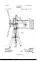
- Figure l is a front view of my windmill thrown out of the wind.
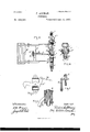
- Fig. 2 is a side view of the yoke, frame, and vane.
- Fig. 3 is a View in detail of the latch by which the vane is held to the wind.
- Fig. 4 is a crosssectiomthrough boxing,ofpump-rod.
- Fig. 5 is a side view of pitman and its connections with pump-rod.
- Fig.6 is a cross-section through Fig. 5.
- A represent the tower, constructed much in the usual way, with four vertical posts converging at the upper ends.
- a collar, B having a flanged rim, B and a vertical web, 13*, upon each side, through the latter of which the collar is secured to the tower by bolts passing through the posts and flanges, as shown.
- the collar extendsabove the top of the posts, so as to form a groove around it below the flange or rim 13*, the object and purpose of which will be hereinafter described.
- a hollow grooved step, D upon which the end of the well tube or pipe 0 operates, and through which the pump rod passes.
- the end of the pipe 0 is beveled,to correspond with the groove D in the step, and the groove is filled with oil, so that the end of the pipe will always be lubricated.
- the well tube or pipe 0 extends up through the flanged collar B and base of the yoke-frame, the latter being bored out to receive the upper end of the said pipe 0, upon which a shoulder may be formed, against which thelower end of the yoke-frame (No model.)
- the yoke for the headgear of the mill consists of a frame, F, cast in one picce,'bored out at the bottom, as before described, and having a square box or lug, F, to receive a packing and lubricant for the working of the upper portion of the pump-rod, lugs G Gr for the journeyna'l-boxes ofthe wind-wheehlugs H H for connecting the vane, and an arm, I, for a pulley, and cushion or spring J.
- the boxing F at the top of the yoke, in which the upper end of the pump-rod works, is cast with a square seat at the base thereof, upon which rests a wooden packing or bearing, F for the pump-rod, held in place within the body by the set-screws F.
- the upper portion of the curved pitman K is bent at an angle of about forty degrees, and to the end of it is cast a hollow collar having interiorly convexcd faces, as shown in Fig. 6, through which collar the pump'rod passes. This collar is held in position upon the pump-rod between the two fixed collars L, situated one above and one below the collar aforesaid.
- the wooden packing or bearing is boiled in oil for three or four days before using, so as to absorb as much oil as possible. It is divided centrally, so as to embrace the pump-rod as it moves up and down in this guide, and when the bearing has a tendency to become heated, the oil will be drawn from the block or blocks of wood composing the bearing and thoroughly lubricate the pump rod, giving off no surplus from the lower end of the .boxing.
- a lug, 1* is secured to the end of the curved arm I of the yokeframe, to which is attached a grooved pulley, 1
- This pulley is so connected to the end of the arm as to operate at an angle of about forty-five degrees, and be in line with the grooved pulley I at the end of the upright arm I, secured to box F.
- a chain or cable, M which enters the hollow pump-rod and extends downward to near the ground, and is weighted at the lower end.
- the upper end of this chain or cable connects with a latch on the vane or tail of the mill.
- the mill is hauled out of the wind with ease and readiness by drawing down the chain or cable, as the location-of the pulleys are such that but little friction is had upon the chain, either in throwing the mill out of the wind or allowing it to adjust itself as against the changes or pressure of the wind.
- the tail or vane N is bolted to the yokeframe through lugs H H".
- the head of the bolt H is placed-downward and engages with the flange B of the collar B; and this is an important feature of my invention, for by this means the head-gear or turn-table is prevented from being lifted up the frame.
- the outer face of the vertical post P which connects the two arms of the vane,has attached to it a spring-latch, P to which the outer end i of the weighted chain or cable M is connected.
- a brace From the vertical yoke-frame extends a brace, 0, having angle-arms Q bolted to the side of Upon the outer end of this brace is made a catch, which, as the vane is thrown backward, engages with the latch on the stud or post and firmly locks and holds the vane out of the wind until the weighted chain or cable '30 is drawn down andlifts the latch from the catch, and permits the vane to be carried back against the arm I of the yoke-frame.
- I In order to take up the shock so incident to this backward and forward movement of the 35 vane, I employ india-rubber springs J, attached to the inner face of the arm 1 back of the pulley and to the outer end of the brace 0 back of the catch, against which the vertical stud or post of the vane cushions as the mill is thrown into or out of the wind.
Landscapes
- Engineering & Computer Science (AREA)
- Life Sciences & Earth Sciences (AREA)
- Sustainable Development (AREA)
- Sustainable Energy (AREA)
- Chemical & Material Sciences (AREA)
- Combustion & Propulsion (AREA)
- Mechanical Engineering (AREA)
- General Engineering & Computer Science (AREA)
- Wind Motors (AREA)
Description
(No Model.)
F. ALTMAN.
WINDMILL.
Patented June 14, 188'7.
2 Sheets-Sheet 1.
Witnesse:
Imrenm r:
(No Model.) 2 Sheets-Sheet 2.
F. ALTMAN.
WINDMILL.
No. 364,983.- Patented June 14, 1887.
IIIIIIIIII MT11E55E5: Inflenfur:
FREDERICK ALTMAN, OF SAN JOSE, CALIFORNIA.
WINDMILL.
SPECIFICATION forming part of Letters Patent No. 364,983, dated June 14, 1887.
Application filed April 22, 1886. Serial No. 199.850.
To all whom, it may concern:
Be it known that I, FREDERICK ALTMAN, a
citizen of the United States, residing at San Jose, in the county of Santa Clara and State of California, have invented certain new and useful Improvements in WVindmill-s, of which the following is a specification.
My invention relates to certain improve ments in windmills; and it consists in the construction, arrangement, and combination of parts, substantially as will be hereinafter described, and then more particularly pointed out in the claim.
In the accompanying drawings, forming a part of this specification, Figure l is a front view of my windmill thrown out of the wind. Fig. 2 is a side view of the yoke, frame, and vane. Fig. 3 is a View in detail of the latch by which the vane is held to the wind. Fig. 4 is a crosssectiomthrough boxing,ofpump-rod. Fig. 5 is a side view of pitman and its connections with pump-rod. Fig.6 is a cross-section through Fig. 5.
Similar letters referto similar parts throughout the several views.
Let A represent the tower, constructed much in the usual way, with four vertical posts converging at the upper ends. \Vithin the converging ends of these posts is set a collar, B, having a flanged rim, B and a vertical web, 13*, upon each side, through the latter of which the collar is secured to the tower by bolts passing through the posts and flanges, as shown. The collar extendsabove the top of the posts, so as to form a groove around it below the flange or rim 13*, the object and purpose of which will be hereinafter described.
Within the tower-posts, and bolted to these. is placed a hollow grooved step, D, upon which the end of the well tube or pipe 0 operates, and through which the pump rod passes. The end of the pipe 0 is beveled,to correspond with the groove D in the step, and the groove is filled with oil, so that the end of the pipe will always be lubricated. The well tube or pipe 0 extends up through the flanged collar B and base of the yoke-frame, the latter being bored out to receive the upper end of the said pipe 0, upon which a shoulder may be formed, against which thelower end of the yoke-frame (No model.)
may rest andlbe kept from contact with the collar B.
The yoke for the headgear of the mill consists of a frame, F, cast in one picce,'bored out at the bottom, as before described, and having a square box or lug, F, to receive a packing and lubricant for the working of the upper portion of the pump-rod, lugs G Gr for thejourna'l-boxes ofthe wind-wheehlugs H H for connecting the vane, and an arm, I, for a pulley, and cushion or spring J. The boxing F at the top of the yoke, in which the upper end of the pump-rod works, is cast with a square seat at the base thereof, upon which rests a wooden packing or bearing, F for the pump-rod, held in place within the body by the set-screws F. The upper portion of the curved pitman K is bent at an angle of about forty degrees, and to the end of it is cast a hollow collar having interiorly convexcd faces, as shown in Fig. 6, through which collar the pump'rod passes. This collar is held in position upon the pump-rod between the two fixed collars L, situated one above and one below the collar aforesaid. By this construction of pitman the movement or thrust will be more nearly in an axial line with the pump-rod than if connected to a right-angled arm, as shown in Fig. 1.
The wooden packing or bearing is boiled in oil for three or four days before using, so as to absorb as much oil as possible. It is divided centrally, so as to embrace the pump-rod as it moves up and down in this guide, and when the bearing has a tendency to become heated, the oil will be drawn from the block or blocks of wood composing the bearing and thoroughly lubricate the pump rod, giving off no surplus from the lower end of the .boxing.
A lug, 1*, is secured to the end of the curved arm I of the yokeframe, to which is attached a grooved pulley, 1 This pulley is so connected to the end of the arm as to operate at an angle of about forty-five degrees, and be in line with the grooved pulley I at the end of the upright arm I, secured to box F. Over these pulleys is passed a chain or cable, M, which enters the hollow pump-rod and extends downward to near the ground, and is weighted at the lower end. The upper end of this chain or cable connects with a latch on the vane or tail of the mill. By this means the mill is hauled out of the wind with ease and readiness by drawing down the chain or cable, as the location-of the pulleys are such that but little friction is had upon the chain, either in throwing the mill out of the wind or allowing it to adjust itself as against the changes or pressure of the wind.
The tail or vane N is bolted to the yokeframe through lugs H H".
The head of the bolt H is placed-downward and engages with the flange B of the collar B; and this is an important feature of my invention, for by this means the head-gear or turn-table is prevented from being lifted up the frame.
bodily in a gale or high wind, in which event the runninggear of the mill would become disarranged.
The outer face of the vertical post P, which connects the two arms of the vane,has attached to it a spring-latch, P to which the outer end i of the weighted chain or cable M is connected.
From the vertical yoke-frame extends a brace, 0, having angle-arms Q bolted to the side of Upon the outer end of this brace is made a catch, which, as the vane is thrown backward, engages with the latch on the stud or post and firmly locks and holds the vane out of the wind until the weighted chain or cable '30 is drawn down andlifts the latch from the catch, and permits the vane to be carried back against the arm I of the yoke-frame.
In order to take up the shock so incident to this backward and forward movement of the 35 vane, I employ india-rubber springs J, attached to the inner face of the arm 1 back of the pulley and to the outer end of the brace 0 back of the catch, against which the vertical stud or post of the vane cushions as the mill is thrown into or out of the wind.
Having thus described my invention, what I claim, and desire to secure by Letters Patent,
In a windmill, the combination of the posts of the tower, the collar B, having web B whereby it is secured between the upper ends of the posts, and having also flange B the vane, and the reversed headed bolt by which the lower arm of said vane connects with flange 13*, substantially as described.
In testimony that I claim the foregoing Ihave hereunto set my hand and seal. Q
FREDERICK ALTMAN. [L. s.]
Witnesses:
O. W. M. SMITH, CHAS. E. KELLY.
Publications (1)
| Publication Number | Publication Date |
|---|---|
| US364983A true US364983A (en) | 1887-06-14 |
Family
ID=2434009
Family Applications (1)
| Application Number | Title | Priority Date | Filing Date |
|---|---|---|---|
| US364983D Expired - Lifetime US364983A (en) | Feedeeick altman |
Country Status (1)
| Country | Link |
|---|---|
| US (1) | US364983A (en) |
-
0
- US US364983D patent/US364983A/en not_active Expired - Lifetime
Similar Documents
| Publication | Publication Date | Title |
|---|---|---|
| US364983A (en) | Feedeeick altman | |
| US609378A (en) | Horizontal windmill | |
| US361894A (en) | Windmill | |
| US449744A (en) | Windmill | |
| US371718A (en) | Windmill | |
| US215661A (en) | Improvement in windmills | |
| US508144A (en) | John h | |
| US233928A (en) | haeeis | |
| US151311A (en) | Ifviprovefvlemtim windmills | |
| US553230A (en) | Windmill | |
| US384756A (en) | aorrell | |
| US235333A (en) | Windmill | |
| US180744A (en) | Improvement in windmills | |
| US228672A (en) | Bmpol | |
| US192787A (en) | Improvement in windmills | |
| US165030A (en) | Improvement in windmills | |
| US160620A (en) | Improvement in windmills | |
| US124021A (en) | Improvement in windmills | |
| US221788A (en) | Improvement in wind-engines | |
| US215036A (en) | Improvement in windmills | |
| US321100A (en) | g-oodeue | |
| US737788A (en) | Windmill. | |
| US366072A (en) | Harry g- | |
| US249437A (en) | Erastus wilson | |
| US211606A (en) | Improvement in windmills |