US3649839A - Light control dead front connector - Google Patents
Light control dead front connector Download PDFInfo
- Publication number
- US3649839A US3649839A US73023A US3649839DA US3649839A US 3649839 A US3649839 A US 3649839A US 73023 A US73023 A US 73023A US 3649839D A US3649839D A US 3649839DA US 3649839 A US3649839 A US 3649839A
- Authority
- US
- United States
- Prior art keywords
- members
- light
- mated
- detector
- electrical
- Prior art date
- Legal status (The legal status is an assumption and is not a legal conclusion. Google has not performed a legal analysis and makes no representation as to the accuracy of the status listed.)
- Expired - Lifetime
Links
- 230000013011 mating Effects 0.000 claims abstract description 11
- 239000000523 sample Substances 0.000 claims description 7
- 230000006872 improvement Effects 0.000 claims description 6
- 230000004044 response Effects 0.000 description 3
- 230000000712 assembly Effects 0.000 description 2
- 238000000429 assembly Methods 0.000 description 2
- 238000010276 construction Methods 0.000 description 2
- 230000004048 modification Effects 0.000 description 2
- 238000012986 modification Methods 0.000 description 2
- 238000000926 separation method Methods 0.000 description 2
- 230000009471 action Effects 0.000 description 1
- 238000007792 addition Methods 0.000 description 1
- 230000008901 benefit Effects 0.000 description 1
- FRLJSGOEGLARCA-UHFFFAOYSA-N cadmium sulfide Chemical compound [S-2].[Cd+2] FRLJSGOEGLARCA-UHFFFAOYSA-N 0.000 description 1
- 229910052980 cadmium sulfide Inorganic materials 0.000 description 1
- 238000010586 diagram Methods 0.000 description 1
- 238000004880 explosion Methods 0.000 description 1
Images
Classifications
-
- H—ELECTRICITY
- H01—ELECTRIC ELEMENTS
- H01R—ELECTRICALLY-CONDUCTIVE CONNECTIONS; STRUCTURAL ASSOCIATIONS OF A PLURALITY OF MUTUALLY-INSULATED ELECTRICAL CONNECTING ELEMENTS; COUPLING DEVICES; CURRENT COLLECTORS
- H01R13/00—Details of coupling devices of the kinds covered by groups H01R12/70 or H01R24/00 - H01R33/00
- H01R13/66—Structural association with built-in electrical component
- H01R13/70—Structural association with built-in electrical component with built-in switch
- H01R13/703—Structural association with built-in electrical component with built-in switch operated by engagement or disengagement of coupling parts, e.g. dual-continuity coupling part
- H01R13/7036—Structural association with built-in electrical component with built-in switch operated by engagement or disengagement of coupling parts, e.g. dual-continuity coupling part the switch being in series with coupling part, e.g. dead coupling, explosion proof coupling
- H01R13/7038—Structural association with built-in electrical component with built-in switch operated by engagement or disengagement of coupling parts, e.g. dual-continuity coupling part the switch being in series with coupling part, e.g. dead coupling, explosion proof coupling making use of a remote controlled switch, e.g. relais, solid state switch activated by the engagement of the coupling parts
Definitions
- one prong of the plug has a light and photocell associated with it when it is in place in the socket so that light is transmitted to the photocell 2% g "250/ thereby indicating that the plug and socket are mated.
- This 1 d g 239 photocell controls a relay having contacts in series between ie 0 arc the electrical source and the socket so as to only close the cip cuit to the socket when the plug and socket are so mated.
- the present invention relates to a fail-safe control apparatus for providing a dead front on a socket except when the mating plus is in the operative position on the socket, and one wherein no physical contact between the control apparatus and the movable elements or the prongs of the plug are required.
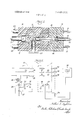
- FIG. 1 is a longitudinal section through an embodiment of the invention
- FIG. 2 is a schematic illustrating the electrical circuitry of the apparatus of FIG. 1;
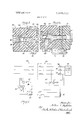
- FIG. 3 is a partial longitudinal section through an altemative embodiment
- FIG. 4 is a partial longitudinal section through a further alternative embodiment.
- FIG. 5 is a schematic of the wiring diagram of the apparatus of FIG. 4.
- the concept of the present invention is applicable to plug-in socket assemblies that might be employed with almost any electrical power capacity.
- the following description is not intended to in any way limit the use of the invention to any particular power application, whether it be single-phase, threephase, I -volt, 440-volt, etc. From the following description, a competent electrical engineer will have no difiiculty in modifying the details of the actual apparatus to achieve an assembly embodying the invention usable for the particular power application with which he is dealing.
- FIG. 1 there is illustrated a mating plug assembly, generally 10, and socket assembly, generally 11.
- the plug assembly has a plurality of prongs (or probes) 12, 13 and 14, which are received in the recesses (such as 150) of a plurality of sockets 15, 16 and 17 respectively, when the plug assembly and socket assembly are mated, so as to provide electrical connections through the two.
- the two are moved relative to each other along an axis which is best illustrated by the longitudinal dimension of prong 12.
- Wires 18, 19 and 20 are connected to the respective prongs 12, 13 and 14.
- Wires 21, 22 and 23 are connected to the respective sockets 15-17.
- a detector apparatus is provided to ascertain when the plug and socket are in the mated condition.
- this detector apparatus comprises a light source consisting of lamp 26 and means (including photocell 27) for producing an electrical switching operation in response to light reception.
- one of the prongs i.e., 12
- one of the prongs is hollow to receive the light bulb 26. It is highly advantageous if the ground prong is employed for this purpose since a number of problems are thereby avoided.
- a wire 28 connects to the light bulb 26 and the other connection to the light bulb can be the grounded prong 12 making contact through a spring arrangement 29.
- Prong 12 has a window (aperture) 30 which registers with a window 31 in socket 15 and an opening 32 in the insulated body 11 when the plug and socket are fully mated together; thus, at that time, the light will be transmitted to photocell 27 which is aligned with the opening 32.
- a relay comprising solenoid 34 and contactors 35, is arranged with its contactors 35 in series between a power source 36 and the electrical socket connections of socket assembly 11.
- the solenoid 34 and the photocell 27 (in the form of a photoresistor) are connected in series with the power source 36.
- Light bulb 26 is connected across a rechargeable battery 37 to be energized thereby.
- a stepdown transformer 38 and a rectifier 39 are employed to form a charging circuit for battery 37.
- the charging circuit in FIG. 2 is merely illustrative and in an actual embodiment would probably be more sophisticated to include a full-wave rectifier and/or a charging limit control, as is well known to those skilled in the art.
- the photocell 27 does not receive light and, as a photoresistor, has a relatively high resistance. This resistance is sufficient so that solenoid 34 is insufl'rciently ener gized and as a result the circuits through the contactors 35 remain open.
- the plug 10 and socket 11 are mated, as illustrated in FIG. 1, the windows 30 and 31 are in registry so that photocell 27 is receiving light. This drops the resistance of the photoresistor to a point such that solenoid 34 picks up its armature to thereby close the circuits through contactors 35.
- the electrical connections of the socket 11 only become energized after the plug and socket are brought into the mating condition.
- FIG. 2 For many applications a photoresistor (FIG. 2) has the advantage of providing a'simple arrangement. However, it does not have a rapid response when the light is removed from it and the relay 34, 35 may continue briefly to supply electrical energy to the sockets 16, 17 after the plug assembly 10 has been separated from the socket assembly 1 1. Thus, it is potentially possible that arcing could occur upon separation and for this reason the construction of FIG. 2 cannot be regarded as explosion proof. If such a situation were a disadvantage in a particular application, it could be remedied by using a photocell and circuit breaking arrangement that had a more rapid response so that between the time that the windows 30 and 31 moved out of registry but before the prong 12 had moved away from its socket 15, the electrical circuit was broken by the opening of contactors 35.
- FIG. 3 illustrates an alternative arrangement in which both the light 26 and the photocell 27 are mounted on the socket assembly, generally 45.
- This socket assembly 45 comprises a body 46 in which there are a plurality of electrical socket connections, only one of which is illustrated at 47.
- the plug assembly, generally 48 likewise includes a plurality of correspondingly positioned prongs, one of which is illustrated at 49.
- Prong 49 has an opening 51 extending thereacross and one side of the prong at this opening forms a reflective surface 52.
- the opening 51 is in registry with openings 53 and 54 in the socket assembly 45.
- the latter openings 53 and 54 are aligned with light 26 and photocell 27, respectively.
- the plug 48 and socket 45 are mated the light beam 55 passes between the two.
- the light beam 55 does not get reflected to the photocell 27.
- the electrical circuitry of FIG. 2 can be employed with the embodiment of FIG. 3.
- FIG. 3 type keeps both the light and the photocell on the socket assembly.
- the special configuration of the active prong is relatively simple. This is particularly desirable arrangement in a situation in which (for one reason or another) it is desired that the active" prong not be a ground prong.
- there is no physical actuation necessary such as, for example, parts of the plug and socket assemblies making electrical contact or pushing a switch, to achieve the control function or signal.
- FIGS. 4 and 5 illustrate several other types of modifications that may be made.
- a plug assembly generally 60
- a socket assembly generally 62
- the prong 61 has a window 65 which registers with a window 66 in socket 64 at the mating position.
- An opening 67 extends through body 63 from window 66 to the light source 68.
- Prong 61 has an axial opening 70 extending from window 65 to a photocell 71.
- a light reflective surface (mirror) 72 is positioned to reflect light from window 65 through opening 70 to photocell 71.
- relay contactors 74 are connected between the power source 36 and the socket assembly 62. These contactors are moved to the closed position by the energizing of a relay solenoid 75.
- the photocell 71 for example, a cadmium sulfide cell provides an electrical signal through amplifier 76 to energize solenoid 75 when the light beam from source 68 is received by the cell.
- a plug and socket arrangement comprising plug 77 and socket 78 are used to connect the amplifier to the solenoid 75. As illustrated in FIG. 4 these may be physically a part of plug assembly 60 and socket assembly 62, or they may be separate components. The most effective action will be obtained if the circuit through plug and socket 77, 78 is accomplished before the prongs of plug assembly 60 enter the electrical socket components of socket assembly 62.
- FIG. 4, FIG. 5, is merely to illustrate various possible modifications.
- provision would be made so that the ambient light through window 65 would not cause photocell 71 to provide an output sigial when the plug assembly 60 was displaced from the socket assembly 62.
- this would be done by using a photocell sensitive only to infrared light and using an infrared light 68.
- an electrical connector apparatus comprising a plug member and a mating socket member which are movable along an axis with respect to each other to connect or disconnect an electrical circuit from a source to which one of the members is connected through a switching device having contacts, the improvement comprising:
- light-transmitting means on a first of said members for producing a beam of light and directing it along a path which, at least in part, extends at an angle to said axis; light reception means, including a detector, on a second of said members and aligned with said part of said path when said members are sufiiciently mated to provide a primary electrical circuit between the members, for directing said beam to said detector for producing an electrical signal, said detector being connected to said switching device to close the contacts thereof when said electrical signal is produced, said light reception means failing to direct said beam to said detector when said members are not sufficiently mated to provide an electrical circuit between the members.
- said second member has a recess parallel to said axis and an opening extending off at an angle from an interior point of said recess, said opening forming a part of the light path to said detector; said first member including a probe which is received in said recess when said members are mated, said probe having an aperture aligned with said opening when said members are mated, said aperture being said part of said path.
- said light transmitting means includes a battery-operated light for producing said beam.
- said first member is said one member, and including interconnecting means on the member for providing a second electrical circuit therebetween when said members are between the condition of being fully mated and the condition of being mated to an extent insufficient to provide said primary electrical circuit, said detector and said switching device being connected to said second electrical circuit.
- an electrical connector apparatus comprising two members having a mated condition and an unmated condition, said members having electrical contacts which provide a primary electrical circuit when the members are mated, one of said members having a recess and the other of said members having a prong which fits into said recess when the members are mated, said members moving along an axis with respect to each other as they are being mated, and electrical switch means connected to one of the members, the improvement comprising:
- a light detector having a first condition when light is received and a second condition when no light is received
- actuating means connecting said detector and said switch means to close said switch means in one of said light conditions and to open said switch means in the other of the light conditions.
Landscapes
- Details Of Connecting Devices For Male And Female Coupling (AREA)
Abstract
In a mating plug and socket assembly one prong of the plug has a light and photocell associated with it when it is in place in the socket so that light is transmitted to the photocell thereby indicating that the plug and socket are mated. This photocell controls a relay having contacts in series between the electrical source and the socket so as to only close the circuit to the socket when the plug and socket are so mated. There are various arrangements of the light and photocell in conjunction with the one prong and the socket.
Description
United States Patent Appleton Mai. M, 1972 [54] LIGHT CONTROL DEAD FRONT CONNECTOR Primary Examiner-James W. Lawrence 72 In tor Arth r l Appleton 1 B 'dle d R ad AssimmEmmm T' G'igsby ven u r1 W 0 Northbrook L 60062 Attorney Darbo, Robertson & Vandenburgh [22] Filed: Sept. 17, 1970 ABSTRACT [21] Appl. No.: 73,023 In a mating plug and socket assembly one prong of the plug has a light and photocell associated with it when it is in place in the socket so that light is transmitted to the photocell 2% g "250/ thereby indicating that the plug and socket are mated. This 1 d g 239 photocell controls a relay having contacts in series between ie 0 arc the electrical source and the socket so as to only close the cip cuit to the socket when the plug and socket are so mated. [56] References cued There are various arrangements of the light and photocell in UNITED STATES PATENTS conjunction with the one prong and the socket.
3,052,816 9/1962 Bernheim ..250/2l5 X 8 Claims, 5 Drawing Figures a 26 V l I PHOTO CELL I 17 27 PATENTEDMAR14 I972 3,649,839
SHEET 2 []F 2 PHOTO CELL 60A 62 r L q 74 36 l 3- I I 4 POWER i i 7 0 SOURCE l I 1 a; 711 l I I o I z I I l 61 6 I I? I 68 I l 1 AMPL I 7 L J L l r- 1 J I" i L L fi J g & J jrujen ar' LIGHT CONTROL DEAD FRONT CONNECTOR SUMMARY OF THE INVENTION The present invention relates to a fail-safe control apparatus for providing a dead front on a socket except when the mating plus is in the operative position on the socket, and one wherein no physical contact between the control apparatus and the movable elements or the prongs of the plug are required.
DESCRIPTION OF THE DRAWING FIG. 1 is a longitudinal section through an embodiment of the invention;
FIG. 2 is a schematic illustrating the electrical circuitry of the apparatus of FIG. 1;
FIG. 3 is a partial longitudinal section through an altemative embodiment;
FIG. 4 is a partial longitudinal section through a further alternative embodiment; and
FIG. 5 is a schematic of the wiring diagram of the apparatus of FIG. 4.
DESCRIPTION OF SPECIFIC EMBODIMENTS The following disclosure is offered for public dissemination in return for the grant of a patent. Although it is detailed to ensure adequacy and aid understanding, this is not intended to prejudice that purpose of a patent which is to cover each new inventive concept therein no matter how others may later disguise it by variations in form or additions or further improvements. The claims at the end hereof are intended as the chief aid toward this purpose, as it is these that meet the requirement of pointing out the parts, improvements, or combinations in which the inventive concepts are found.
The concept of the present invention is applicable to plug-in socket assemblies that might be employed with almost any electrical power capacity. The following description is not intended to in any way limit the use of the invention to any particular power application, whether it be single-phase, threephase, I -volt, 440-volt, etc. From the following description, a competent electrical engineer will have no difiiculty in modifying the details of the actual apparatus to achieve an assembly embodying the invention usable for the particular power application with which he is dealing.
In FIG. 1 there is illustrated a mating plug assembly, generally 10, and socket assembly, generally 11. The plug assembly has a plurality of prongs (or probes) 12, 13 and 14, which are received in the recesses (such as 150) of a plurality of sockets 15, 16 and 17 respectively, when the plug assembly and socket assembly are mated, so as to provide electrical connections through the two. To achieve mating or separation the two are moved relative to each other along an axis which is best illustrated by the longitudinal dimension of prong 12. Wires 18, 19 and 20 are connected to the respective prongs 12, 13 and 14. Wires 21, 22 and 23 are connected to the respective sockets 15-17.
A detector apparatus is provided to ascertain when the plug and socket are in the mated condition. In accordance with the present invention, this detector apparatus comprises a light source consisting of lamp 26 and means (including photocell 27) for producing an electrical switching operation in response to light reception. In the embodiment of FIG. 1, one of the prongs (i.e., 12) is hollow to receive the light bulb 26. It is highly advantageous if the ground prong is employed for this purpose since a number of problems are thereby avoided. A wire 28 connects to the light bulb 26 and the other connection to the light bulb can be the grounded prong 12 making contact through a spring arrangement 29. Prong 12 has a window (aperture) 30 which registers with a window 31 in socket 15 and an opening 32 in the insulated body 11 when the plug and socket are fully mated together; thus, at that time, the light will be transmitted to photocell 27 which is aligned with the opening 32.
Referring to FIG. 2, a relay, comprising solenoid 34 and contactors 35, is arranged with its contactors 35 in series between a power source 36 and the electrical socket connections of socket assembly 11. The solenoid 34 and the photocell 27 (in the form of a photoresistor) are connected in series with the power source 36. Light bulb 26 is connected across a rechargeable battery 37 to be energized thereby. A stepdown transformer 38 and a rectifier 39 are employed to form a charging circuit for battery 37. The charging circuit in FIG. 2 is merely illustrative and in an actual embodiment would probably be more sophisticated to include a full-wave rectifier and/or a charging limit control, as is well known to those skilled in the art.
So long as the windows 30 and 31 of the prong and socket are not in registry, the photocell 27 does not receive light and, as a photoresistor, has a relatively high resistance. This resistance is sufficient so that solenoid 34 is insufl'rciently ener gized and as a result the circuits through the contactors 35 remain open. However, when the plug 10 and socket 11 are mated, as illustrated in FIG. 1, the windows 30 and 31 are in registry so that photocell 27 is receiving light. This drops the resistance of the photoresistor to a point such that solenoid 34 picks up its armature to thereby close the circuits through contactors 35. Thus, the electrical connections of the socket 11 only become energized after the plug and socket are brought into the mating condition.
For many applications a photoresistor (FIG. 2) has the advantage of providing a'simple arrangement. However, it does not have a rapid response when the light is removed from it and the relay 34, 35 may continue briefly to supply electrical energy to the sockets 16, 17 after the plug assembly 10 has been separated from the socket assembly 1 1. Thus, it is potentially possible that arcing could occur upon separation and for this reason the construction of FIG. 2 cannot be regarded as explosion proof. If such a situation were a disadvantage in a particular application, it could be remedied by using a photocell and circuit breaking arrangement that had a more rapid response so that between the time that the windows 30 and 31 moved out of registry but before the prong 12 had moved away from its socket 15, the electrical circuit was broken by the opening of contactors 35.
FIG. 3 illustrates an alternative arrangement in which both the light 26 and the photocell 27 are mounted on the socket assembly, generally 45. This socket assembly 45 comprises a body 46 in which there are a plurality of electrical socket connections, only one of which is illustrated at 47. The plug assembly, generally 48, likewise includes a plurality of correspondingly positioned prongs, one of which is illustrated at 49.
Prong 49 has an opening 51 extending thereacross and one side of the prong at this opening forms a reflective surface 52. When the plug 48 and socket 45 are fully mated the opening 51 is in registry with openings 53 and 54 in the socket assembly 45. The latter openings 53 and 54 are aligned with light 26 and photocell 27, respectively. When the plug 48 and socket 45 are mated the light beam 55 passes between the two. However, when prong 49 is not in place, the light beam 55 does not get reflected to the photocell 27. In some such embodiments it may be desirable to blacken the inner walls about opening 56 to insure that it forms a light sink and that no light is reflected when the prong 49 is not in place. The electrical circuitry of FIG. 2 can be employed with the embodiment of FIG. 3.
An arrangement of the FIG. 3 type keeps both the light and the photocell on the socket assembly. Also, the special configuration of the active prong is relatively simple. This is particularly desirable arrangement in a situation in which (for one reason or another) it is desired that the active" prong not be a ground prong. Like the other embodiments, there is no physical actuation necessary, such as, for example, parts of the plug and socket assemblies making electrical contact or pushing a switch, to achieve the control function or signal.
FIGS. 4 and 5 illustrate several other types of modifications that may be made. Here there is a plug assembly, generally 60, which has a plurality of electrically conductive prongs, one of which is shown at 61. There is a socket assembly, generally 62, comprising a body 63 having a plurality of electrically conductive sockets, one of which is shown at 64. The prong 61 has a window 65 which registers with a window 66 in socket 64 at the mating position. An opening 67 extends through body 63 from window 66 to the light source 68. Prong 61 has an axial opening 70 extending from window 65 to a photocell 71. A light reflective surface (mirror) 72 is positioned to reflect light from window 65 through opening 70 to photocell 71.
Referring to FIG. 5, relay contactors 74 are connected between the power source 36 and the socket assembly 62. These contactors are moved to the closed position by the energizing of a relay solenoid 75. The photocell 71, for example, a cadmium sulfide cell provides an electrical signal through amplifier 76 to energize solenoid 75 when the light beam from source 68 is received by the cell. A plug and socket arrangement comprising plug 77 and socket 78 are used to connect the amplifier to the solenoid 75. As illustrated in FIG. 4 these may be physically a part of plug assembly 60 and socket assembly 62, or they may be separate components. The most effective action will be obtained if the circuit through plug and socket 77, 78 is accomplished before the prongs of plug assembly 60 enter the electrical socket components of socket assembly 62.
The particular arrangement of FIG. 4, FIG. 5, is merely to illustrate various possible modifications. In an actual construction provision would be made so that the ambient light through window 65 would not cause photocell 71 to provide an output sigial when the plug assembly 60 was displaced from the socket assembly 62. For example, this would be done by using a photocell sensitive only to infrared light and using an infrared light 68.
The invention claimed is:
1. In an electrical connector apparatus comprising a plug member and a mating socket member which are movable along an axis with respect to each other to connect or disconnect an electrical circuit from a source to which one of the members is connected through a switching device having contacts, the improvement comprising:
light-transmitting means on a first of said members for producing a beam of light and directing it along a path which, at least in part, extends at an angle to said axis; light reception means, including a detector, on a second of said members and aligned with said part of said path when said members are sufiiciently mated to provide a primary electrical circuit between the members, for directing said beam to said detector for producing an electrical signal, said detector being connected to said switching device to close the contacts thereof when said electrical signal is produced, said light reception means failing to direct said beam to said detector when said members are not sufficiently mated to provide an electrical circuit between the members.
2. In an apparatus as set forth in claim 1, wherein said second member has a recess parallel to said axis and an opening extending off at an angle from an interior point of said recess, said opening forming a part of the light path to said detector; said first member including a probe which is received in said recess when said members are mated, said probe having an aperture aligned with said opening when said members are mated, said aperture being said part of said path.
3. In an apparatus as set forth in claim 2, wherein said light transmitting means includes a battery-operated light for producing said beam.
4. In an apparatus as set forth in claim 3, including a rechargeable battery for said light and battery-recharging means for said battery.
5. In an apparatus as set forth in claim 2, wherein said members have a plurality of mating prongs and sockets parallel to said axis for providing said primary circuit, one of said prongs bein said probe and also bein the ground prong.
6. it an apparatus as set orth in claim 1, wherein said second member is said one member.
7. In an apparatus as set forth in claim I, wherein said first member is said one member, and including interconnecting means on the member for providing a second electrical circuit therebetween when said members are between the condition of being fully mated and the condition of being mated to an extent insufficient to provide said primary electrical circuit, said detector and said switching device being connected to said second electrical circuit.
8. In an electrical connector apparatus comprising two members having a mated condition and an unmated condition, said members having electrical contacts which provide a primary electrical circuit when the members are mated, one of said members having a recess and the other of said members having a prong which fits into said recess when the members are mated, said members moving along an axis with respect to each other as they are being mated, and electrical switch means connected to one of the members, the improvement comprising:
a source of light;
a light detector having a first condition when light is received and a second condition when no light is received;
means defining a light path between said source and said detector when said members are in one of said conditions thereof, with said light not being received by said detector at the other condition of the members, at least a portion of said path being angularly disposed to said axis at a location of a portion of said prong when said members are mated; and
actuating means connecting said detector and said switch means to close said switch means in one of said light conditions and to open said switch means in the other of the light conditions.
Claims (8)
1. In an electrical connector apparatus comprising a plug member and a mating socket member which are movable along an axis with respect to each other to connect or disconnect an electrical circuit from a source to which one of the members is connected through a switching device having contacts, the improvement comprising: light-transmitting means on a first of said members for producing a beam of light and directing it along a path which, at least in part, extends at an angle to said axis; light reception means, including a detector, on a second of said members and aligned with said part of said path when said members are sufficiently mated to provide a primary electrical circuit between the members, for directing said beam to said detector for producing an electrical signal, said detector being connected to said switching device to close the contacts thereof when said electrical signal is produced, said light reception means failing to direct said beam to said detector when said members aRe not sufficiently mated to provide an electrical circuit between the members.
2. In an apparatus as set forth in claim 1, wherein said second member has a recess parallel to said axis and an opening extending off at an angle from an interior point of said recess, said opening forming a part of the light path to said detector; said first member including a probe which is received in said recess when said members are mated, said probe having an aperture aligned with said opening when said members are mated, said aperture being said part of said path.
3. In an apparatus as set forth in claim 2, wherein said light transmitting means includes a battery-operated light for producing said beam.
4. In an apparatus as set forth in claim 3, including a rechargeable battery for said light and battery-recharging means for said battery.
5. In an apparatus as set forth in claim 2, wherein said members have a plurality of mating prongs and sockets parallel to said axis for providing said primary circuit, one of said prongs being said probe and also being the ground prong.
6. In an apparatus as set forth in claim 1, wherein said second member is said one member.
7. In an apparatus as set forth in claim 1, wherein said first member is said one member, and including interconnecting means on the member for providing a second electrical circuit therebetween when said members are between the condition of being fully mated and the condition of being mated to an extent insufficient to provide said primary electrical circuit, said detector and said switching device being connected to said second electrical circuit.
8. In an electrical connector apparatus comprising two members having a mated condition and an unmated condition, said members having electrical contacts which provide a primary electrical circuit when the members are mated, one of said members having a recess and the other of said members having a prong which fits into said recess when the members are mated, said members moving along an axis with respect to each other as they are being mated, and electrical switch means connected to one of the members, the improvement comprising: a source of light; a light detector having a first condition when light is received and a second condition when no light is received; means defining a light path between said source and said detector when said members are in one of said conditions thereof, with said light not being received by said detector at the other condition of the members, at least a portion of said path being angularly disposed to said axis at a location of a portion of said prong when said members are mated; and actuating means connecting said detector and said switch means to close said switch means in one of said light conditions and to open said switch means in the other of the light conditions.
Applications Claiming Priority (1)
| Application Number | Priority Date | Filing Date | Title |
|---|---|---|---|
| US7302370A | 1970-09-17 | 1970-09-17 |
Publications (1)
| Publication Number | Publication Date |
|---|---|
| US3649839A true US3649839A (en) | 1972-03-14 |
Family
ID=22111236
Family Applications (1)
| Application Number | Title | Priority Date | Filing Date |
|---|---|---|---|
| US73023A Expired - Lifetime US3649839A (en) | 1970-09-17 | 1970-09-17 | Light control dead front connector |
Country Status (2)
| Country | Link |
|---|---|
| US (1) | US3649839A (en) |
| CA (1) | CA932057A (en) |
Cited By (11)
| Publication number | Priority date | Publication date | Assignee | Title |
|---|---|---|---|---|
| FR2502134A1 (en) * | 1981-03-19 | 1982-09-24 | Lebret Eric | Anti-fraud device for fluid dispenser e.g. petrol pump - includes magnetic sensors on dispenser responding to coded magnets around filler pipe of receiving tank |
| FR2567331A1 (en) * | 1984-07-09 | 1986-01-10 | Vibrachoc Sa | DEVICE FOR VISUALIZING THE PLUG OF ELECTRICAL CONNECTORS ON AN AIRCRAFT TRAY |
| US5048914A (en) * | 1987-12-18 | 1991-09-17 | Nl Petroleum Services (U.K.) Limited | Electrical connectors incorporating automatic power control |
| US5222164A (en) * | 1992-08-27 | 1993-06-22 | International Business Machines Corporation | Electrically isolated optical connector identification system |
| US6305989B1 (en) | 1999-08-30 | 2001-10-23 | Emerson Electric Co. | Connector block for a terminal assembly |
| US6554484B2 (en) * | 2000-12-27 | 2003-04-29 | Fitel Usa Corp. | Optical connector receptacle having switching capability |
| US20030119373A1 (en) * | 2001-12-21 | 2003-06-26 | Tariq Quadir | Connector block having at least one protrusion, for a terminal assembly |
| ITBA20090017A1 (en) * | 2009-05-12 | 2010-11-13 | Adf Work & Service S R L | MECHATRONIC SOCKETS FOR CIVIL / INDUSTRIAL SERIES WITH RELATIVE ELECTRICITY SWITCHING SYSTEMS THROUGH EARTH POTENTIAL. |
| US8651892B2 (en) * | 2012-03-14 | 2014-02-18 | Ford Global Technologies, Llc | Visual mating detector for electrical connector |
| US10038283B2 (en) | 2016-05-24 | 2018-07-31 | Hubbell Incorporated | Electrical receptacle |
| DE102024107348A1 (en) * | 2024-03-14 | 2025-09-18 | HARTING Stiftung & Co. KG | Connector system for connecting and disconnecting connectors under load |
Families Citing this family (2)
| Publication number | Priority date | Publication date | Assignee | Title |
|---|---|---|---|---|
| CA1211179A (en) * | 1983-10-28 | 1986-09-09 | Fernand H. Poulin | Electrical receptacle |
| US4784611A (en) * | 1987-08-18 | 1988-11-15 | Poulin Fernand H | Locking plug |
Citations (1)
| Publication number | Priority date | Publication date | Assignee | Title |
|---|---|---|---|---|
| US3052816A (en) * | 1960-12-14 | 1962-09-04 | George W Bernheim | Thermal relay switching circuit |
-
1970
- 1970-09-17 US US73023A patent/US3649839A/en not_active Expired - Lifetime
-
1971
- 1971-09-10 CA CA122554A patent/CA932057A/en not_active Expired
Patent Citations (1)
| Publication number | Priority date | Publication date | Assignee | Title |
|---|---|---|---|---|
| US3052816A (en) * | 1960-12-14 | 1962-09-04 | George W Bernheim | Thermal relay switching circuit |
Cited By (15)
| Publication number | Priority date | Publication date | Assignee | Title |
|---|---|---|---|---|
| FR2502134A1 (en) * | 1981-03-19 | 1982-09-24 | Lebret Eric | Anti-fraud device for fluid dispenser e.g. petrol pump - includes magnetic sensors on dispenser responding to coded magnets around filler pipe of receiving tank |
| FR2567331A1 (en) * | 1984-07-09 | 1986-01-10 | Vibrachoc Sa | DEVICE FOR VISUALIZING THE PLUG OF ELECTRICAL CONNECTORS ON AN AIRCRAFT TRAY |
| EP0172373A1 (en) * | 1984-07-09 | 1986-02-26 | VIBRACHOC, Société Anonyme dite: | Device for visualizing the plugging in of electrical connectors into an airship loading platform |
| US4667094A (en) * | 1984-07-09 | 1987-05-19 | Vibrachoc | Optical indicator system for aircraft pallet connector-mating |
| US5048914A (en) * | 1987-12-18 | 1991-09-17 | Nl Petroleum Services (U.K.) Limited | Electrical connectors incorporating automatic power control |
| US5222164A (en) * | 1992-08-27 | 1993-06-22 | International Business Machines Corporation | Electrically isolated optical connector identification system |
| US6305989B1 (en) | 1999-08-30 | 2001-10-23 | Emerson Electric Co. | Connector block for a terminal assembly |
| US6554484B2 (en) * | 2000-12-27 | 2003-04-29 | Fitel Usa Corp. | Optical connector receptacle having switching capability |
| US20030119373A1 (en) * | 2001-12-21 | 2003-06-26 | Tariq Quadir | Connector block having at least one protrusion, for a terminal assembly |
| US6699078B2 (en) | 2001-12-21 | 2004-03-02 | Emerson Electric Co. | Connector block having at least one protrusion, for a terminal assembly |
| ITBA20090017A1 (en) * | 2009-05-12 | 2010-11-13 | Adf Work & Service S R L | MECHATRONIC SOCKETS FOR CIVIL / INDUSTRIAL SERIES WITH RELATIVE ELECTRICITY SWITCHING SYSTEMS THROUGH EARTH POTENTIAL. |
| US8651892B2 (en) * | 2012-03-14 | 2014-02-18 | Ford Global Technologies, Llc | Visual mating detector for electrical connector |
| US10038283B2 (en) | 2016-05-24 | 2018-07-31 | Hubbell Incorporated | Electrical receptacle |
| DE102024107348A1 (en) * | 2024-03-14 | 2025-09-18 | HARTING Stiftung & Co. KG | Connector system for connecting and disconnecting connectors under load |
| WO2025191382A1 (en) * | 2024-03-14 | 2025-09-18 | HARTING Stiftung & Co. KG | Plug-in connector system, method for connection and disconnection, and electrical power supply system |
Also Published As
| Publication number | Publication date |
|---|---|
| CA932057A (en) | 1973-08-14 |
Similar Documents
| Publication | Publication Date | Title |
|---|---|---|
| US3649839A (en) | Light control dead front connector | |
| US5095182A (en) | Shockproof safety outlet | |
| US5391087A (en) | Connector | |
| US5118301A (en) | Electrical connector device | |
| ES552395A0 (en) | UNIPOLAR AND NEUTRAL DIFFERENTIAL CIRCUIT BREAKER | |
| US4944697A (en) | Automotive fuse connector | |
| EP0282119B1 (en) | Assembly of a headlight and a connector | |
| US3991320A (en) | Electric branch-line combiner | |
| ES2010644A4 (en) | MULTIPOLAR ELECTRIC PLUG DEVICE | |
| JPS60261444A (en) | Light conductor connection apparatus for medical laser apparatus | |
| ATE95641T1 (en) | ELECTRICAL PROTECTIVE SOCKET. | |
| US4710720A (en) | Arrangement for testing fuses | |
| US4491781A (en) | Patch cord tester | |
| AU556504B2 (en) | Electrical switchgear test terminal arrangement | |
| US3207956A (en) | Electrical component mounting and connection terminal block | |
| EP0112311B1 (en) | A method for accomplishing a time relay function, and a device for utilization of the method | |
| CN221465923U (en) | Function testing device | |
| ATE38712T1 (en) | SAFETY DEVICE FOR AN ELECTRICAL DEVICE WITH RECHARGEABLE ACCUMULATOR. | |
| JPH03250514A (en) | Circuit breaker | |
| JPS6346986Y2 (en) | ||
| JPH0648885Y2 (en) | connector | |
| JPS60214272A (en) | Confirming device for continuity of grounding device | |
| JPS6214612Y2 (en) | ||
| GB2214734A (en) | Residual current circuit breaker | |
| SU518815A1 (en) | High voltage shunt device |
Legal Events
| Date | Code | Title | Description |
|---|---|---|---|
| AS | Assignment |
Owner name: EMERSON ELECTRIC CO., A CORP. OF MO. Free format text: ASSIGNMENT OF ASSIGNORS INTEREST.;ASSIGNOR:ARTHUR I. APPLETON;REEL/FRAME:004043/0926 Effective date: 19820322 |