US3649830A - Uniform charging method and apparatus using an array of needle electrodes - Google Patents
Uniform charging method and apparatus using an array of needle electrodes Download PDFInfo
- Publication number
- US3649830A US3649830A US86449A US3649830DA US3649830A US 3649830 A US3649830 A US 3649830A US 86449 A US86449 A US 86449A US 3649830D A US3649830D A US 3649830DA US 3649830 A US3649830 A US 3649830A
- Authority
- US
- United States
- Prior art keywords
- electrodes
- charged
- coupled
- electric potential
- needle
- Prior art date
- Legal status (The legal status is an assumption and is not a legal conclusion. Google has not performed a legal analysis and makes no representation as to the accuracy of the status listed.)
- Expired - Lifetime
Links
- 238000007600 charging Methods 0.000 title claims abstract description 24
- 238000000034 method Methods 0.000 title claims abstract description 12
- 230000008878 coupling Effects 0.000 claims description 2
- 238000010168 coupling process Methods 0.000 claims description 2
- 238000005859 coupling reaction Methods 0.000 claims description 2
- 238000007786 electrostatic charging Methods 0.000 description 10
- 239000000463 material Substances 0.000 description 5
- 238000005421 electrostatic potential Methods 0.000 description 3
- 239000002184 metal Substances 0.000 description 3
- 238000005513 bias potential Methods 0.000 description 2
- 230000005684 electric field Effects 0.000 description 2
- 230000000694 effects Effects 0.000 description 1
- 230000003287 optical effect Effects 0.000 description 1
- 230000000737 periodic effect Effects 0.000 description 1
- 230000002093 peripheral effect Effects 0.000 description 1
- 239000013598 vector Substances 0.000 description 1
Images
Classifications
-
- G—PHYSICS
- G03—PHOTOGRAPHY; CINEMATOGRAPHY; ANALOGOUS TECHNIQUES USING WAVES OTHER THAN OPTICAL WAVES; ELECTROGRAPHY; HOLOGRAPHY
- G03G—ELECTROGRAPHY; ELECTROPHOTOGRAPHY; MAGNETOGRAPHY
- G03G15/00—Apparatus for electrographic processes using a charge pattern
- G03G15/02—Apparatus for electrographic processes using a charge pattern for laying down a uniform charge, e.g. for sensitising; Corona discharge devices
- G03G15/0291—Apparatus for electrographic processes using a charge pattern for laying down a uniform charge, e.g. for sensitising; Corona discharge devices corona discharge devices, e.g. wires, pointed electrodes, means for cleaning the corona discharge device
Definitions
- ABSTRACT (22] Wed: 1970 Charging method and apparatus for applying a uniform charge [21] Appl. No.: 86,449 to a surface in which an array of needle electrodes is moved relative to the surface, and a source of relatively high electric potential is coupled to alternate ones of the electrodes on each g pass in inverse order. The remaining alternate electrodes are coupled to a source of relatively low electric potential or A [58] Field of Search ..250/49.5 ZC, 317/262A ground. By switching the potentials on each pass a uniform charge is obtained. In one embodiment a lattice-type arrange- [56] References Cited ment is utilized with alternate rows of electrodes offset from UNITED STATES PATENTS an adjacent row to provide the desired uniform charge.
- Such a method is sometimes undesirable in the machines in which succeeding steps such as exposure or processing are carried out automatically, however, since the devices for such steps which are usually arranged perpendicularly to said moving direction will result in the deviation of time in different portions of said surface from said electrostatic charge to said succeeding steps if said electrodes are arranged obliquely with respect to said moving direction. Also such method requires larger space for charging device in such automatic machine. Nevertheless uneven charging such as explained above should be strictly prevented in case of reproducing images containing continuous tone or wide area of uniform optical density since this will deteriorate significantly the quality of reproduced image.
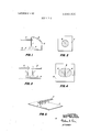
- FIG. I and FIG. 3 are side views showing electrostatic charging respectively, with one and two needle electrodes;
- FIG. 2 and FIG. 4 are plan views showing charge distribution obtainable respectively in FIG. 1 and FIG. 3;
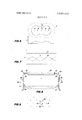
- FIG. 5 is a perspective view of a device for displacing the surface to be electrostatically charged in a direction perpendicular to a line of plural needle electrodes;
- FIG. 6 is a plan view of arrangement of needle electrodes according to this invention and electrostatic potential distribution obtained therewith;
- FIG. 7 shows electrostatic potential distribution obtained by another arrangement of needle electrodes according to this invention.
- FIG. 8 is a plan view representing an example of a mechanism for switching the polarity of applied potential.
- FIG. 9 is a plan view of still another arrangement of needle electrodes.
- FIG. 1 which shows electrostatic charging with one needle electrode shown is a pointed needle electrode 1, an insulating rod 2 for supporting the electrode 1, a material or surface to be charged 3 such as electrophotographic photosensitive sheet or electrostatographic recording sheet, a metal support 4 for said material and working also as an electrode, a direct current high-voltage source 5 and an electroconductive wire 6 for applying a high electric potential between the needle electrode 1 and the metal support 4.
- the direction of the electric field between the point of the electrode I and the metal support 4 is shown by the lines 7.
- Electrostatic charging on the surface 3 is commenced by corona discharge, and after the application of electric potential is terminated there remains electrostatic charge in nearly circular shape on surface 3 which can be electrophotographically developed to give visible distribution of said electrostatic charge, as shown in FIG. 2.
- the center 8 of the circle in this figure is located below the needle electrode 1 in FIG. 1 and the radius is determined by many factors such as applied potential, charging period, the distance between the needle electrode 1 and the surface 3, the diameter of point of said electrode 1 etc. If the electrode 1 is not perpendicular to the surface, the center 8 so circular is no longer located below the electrode 1 but displaces according to the inclination of said electrode.
- FIG. 3 shows the electrostatic charging with two needle electrode.
- the repulsion appearing between the electric fields induced by electrodes 1 and l of the same potential gives a distorted charge pattern as shown in FIG. 4.
- the repulsion becomes more apparent when two electrodes are relatively close to form a boundary region 9 with no or little charge on a plane perpendicular to said electrodes and along the bisecting plane thereof, as shown in FIG. 4, in which charge pattern consists of two symmetric hemicycles with the centers 8 and 8' respectively below the electrodes 1 and 1'.
- This pattern becomes undistorted circles if the electrodes are sufficiently distant from each other or the potential applied is sufficiently low, and the potential gradient in the distorted portion in FIG. 4 is much larger than that in FIG. 1 or FIG. 2.
- a novel electrostatic charging device using needle electrodes capable of providing a uniform electrostatic charge.
- FIG. 6 shows, corresponding to FIG. 4, a plane view of charge distribution obtained according to this invention, in which marks8 and 8 respectively indicate the positions below high potential needle electrodes and low potential needle electrodes which are grounded or applied with lower bias potential.
- the line 10 shows the boundary of electrostatic charge obtainable when charging is carried out when the surface to be charged is kept standstill with respect to said electrodes. Boundary 10 is made unclear because the high potential electrodes 8 give peripheral charge region of relatively low potential 11 due to the presence of lower potential electrodes 8.
- FIG. 7 there is shown in the distribution of charge potential in a direction parallel to a row of needle electrodes consisting of alternatively arranged high and low potential electrodes, obtained on the surface'to be charged when said surface is displaced perpendicularly with respect to said row. If charging is carried out while said material to be charged is reciprocated with inversed potential difference in forward and backward movement, the periodic charge distribution in forward movement shown in solid line w and that in backward movement shown in broken line y are added, compensating each other, to give a uniform charge distribution as shown by the top line 2 in FIG. 7.
- FIG. 8 is a plan view of an electrostatic charging device in which high potential electrodes and low potential electrodes are switched automatically in forward and backward movement.
- an insulative electrode support 20 is provided with two sets of electrodes marked with and x, respectively, arranged alternatively and with substantially equal spacings.
- Support 20 is also provided with elastic arms 21, which are respectively provided with two brushes 22, 22, 23 and 23.
- a set of electrodes marked with x" is electrically connected with the brushes 22 and 23' whereas another set being' connected with the brushes 22 and 23 whereas another set being connected with the brushes 22' and 23.
- Electroconductive guide rails 24 and 24 are installed with a distance shorter than that between the extremities of brushes 22 and 23 or 22' and 23, and are respectively connected to a high voltage source 25 and to a suitable bias potential or to ground.
- the arms 21 are bent as shown in the operating position making electric contacts between the brush 22' and guide rail 24 and between 23' and 24, leaving brushes 22 and 23 uncontacted.
- the electrodes marked x are applied with a high potential whereas those marked are applied with a low potential or grounded.
- Application of potentials is interrupted when the support 20 proceeds further to pass through said guide rails.
- FIG. 9 shows the general distribution of needle electrodes according to this invention, in which the electrodes are placed on the lattice points 30, 31, 32, 33 of two-dimensional oblique lattice composed of two basic translation vectors a and b, and
- At least one electrode placed on the lattice points of the basic lattice is grounded or applied with a low potential while the remaining electrodes are applied with a high potential.
- the electrodes and the surface should be displaced, with respect to each other, so that the electrodes pass the surface at least two times.
- the number of said passes is preferably even in order to invert the potential in half of such passes, but can also be odd when said number is fairly large. Two passes or one reciprocation are sufficient for most purposes.
- the charging device of this invention is capable of fonning uniform electrostatic charge while still fully utilizing the advantages of prior devices with needle electrodes.
- Charging apparatus for applying a uniform electrostatic charge to a surface comprising a linear array of needle electrodes uniformly spaced and extending perpendicular to a surface to be charged,
- circuit means for causing relative movement between said electrodes and the surfaceto be charged and circuit means for coupling a source of relatively high DC electric potential to alternate ones of said electrodes and an electric. potential substantially at ground to the remaining electrodes,
- said means for causing relative movement operates to reciprocate the electrodes past the surface to be charged
- said circuit means is operative to inverse the different potentials coupled to alternate ones of the electrodes upon each pass.
- Charging apparatus for applying a unifonn electrostatic charge to a surface comprising an array of needle electrodes arranged in lattice form overlying a surface to be charged,
- circuit means for switching potentials of said electrodes on each pass.
- a method of uniformly charging a xerographic surface comprising the steps of alternatively arranging needle electrodes coupled to a relatively high source of DC potential and an electric potential substantially at ground in overlying relation to a surface to be charged,
Landscapes
- Physics & Mathematics (AREA)
- Engineering & Computer Science (AREA)
- Plasma & Fusion (AREA)
- General Physics & Mathematics (AREA)
- Electrostatic Charge, Transfer And Separation In Electrography (AREA)
Abstract
Charging method and apparatus for applying a uniform charge to a surface in which an array of needle electrodes is moved relative to the surface, and a source of relatively high electric potential is coupled to alternate ones of the electrodes on each pass in inverse order. The remaining alternate electrodes are coupled to a source of relatively low electric potential or ground. By switching the potentials on each pass a uniform charge is obtained. In one embodiment a lattice-type arrangement is utilized with alternate rows of electrodes offset from an adjacent row to provide the desired uniform charge.
Description
United States Patent Sato et al. 51 Mar. 14, 1972 [54] UNIFORM CHARGING METHOD AND 3,076,092 1/ 1963 Mott ..250l49.5 APPARATUS USING AN ARRAY 01? 3,147,415 9/1964 Oliphant ..317/262 NEEDLE ELECTRODES Pnmary Examiner-William F. Lindqulst Invenlofsi Mlsllmichi i Tflhlllshi, bOlh 0f Attorney-James J. Ralabate, Norman E. Schrader and Melvin Asaka, Japan A, Klein [73] Assignee: Xerox Corporation, Stamford, Conn. [57] ABSTRACT [22] Wed: 1970 Charging method and apparatus for applying a uniform charge [21] Appl. No.: 86,449 to a surface in which an array of needle electrodes is moved relative to the surface, and a source of relatively high electric potential is coupled to alternate ones of the electrodes on each g pass in inverse order. The remaining alternate electrodes are coupled to a source of relatively low electric potential or A [58] Field of Search ..250/49.5 ZC, 317/262A ground. By switching the potentials on each pass a uniform charge is obtained. In one embodiment a lattice-type arrange- [56] References Cited ment is utilized with alternate rows of electrodes offset from UNITED STATES PATENTS an adjacent row to provide the desired uniform charge. 2,918,580 12/1959 Howell ..250/49.5 3 Claims, 9 Drawing Figures 22 2/ 2.3 1*} FE 1Y1: '1' 22' 23' 24 l 24 PATENTEDMAR 14 I972 3. 649,830
INVENTORS. MASAMICHI SATO ISOJI TAKAHASHI MAM ATTORNEY UNIFORM CHARGING METHOD AND APPARATUS USING AN ARRAY OF NEEDLE ELECTRODES along the wire resulting in ununiform electrostatic charging particularly especially in the case of negative corona discharge and lower charging efficiency induced by shield plates required between the corona wires if plural wires are em- 'ployed, as for example, in order to increase the charging speed. Also such device requires larger volume when the number of corona wires are increased. On the other hand the device with needle electrodes, though requiring a plurality of electrodes to be arranged in a row and therefore involving more complicated mechanical works, enables using a lower charging potential and reduces the total glow of corona discharge.
The arrangement of needle electrodes repeated at a certain interval generally result, however, in an electrostatic potential distribution which is not uniform but rather shows repeated pattern corresponding to the arrangement of said electrodes. More detailedly such pattern appears in streaks along the direction of movement of the surface to be charged with respect to said needle electrodes. It is described in British Pat. No. 1,063,913 that such streaking potential fluctuation can be reduced by choosing the moving direction of the surface to be charged so as not to be perpendicular with respect to the line of needle electrodes. Such a method is sometimes undesirable in the machines in which succeeding steps such as exposure or processing are carried out automatically, however, since the devices for such steps which are usually arranged perpendicularly to said moving direction will result in the deviation of time in different portions of said surface from said electrostatic charge to said succeeding steps if said electrodes are arranged obliquely with respect to said moving direction. Also such method requires larger space for charging device in such automatic machine. Nevertheless uneven charging such as explained above should be strictly prevented in case of reproducing images containing continuous tone or wide area of uniform optical density since this will deteriorate significantly the quality of reproduced image.
It is therefore a primary object of the invention to improve needle electrodes.
It is also an object of this invention to provide an electrostatic charging device using needle electrodes utilizing all the advantages thereof effectively and preventing the drawbacks associated with the wire electrode to achieve a high efficiency which could not be reached with prior devices.
In the following is explained details of the general characteristics of a charging device with corona needle electrode in particular reference with the attached drawings in which:
FIG. I and FIG. 3 are side views showing electrostatic charging respectively, with one and two needle electrodes;
FIG. 2 and FIG. 4 are plan views showing charge distribution obtainable respectively in FIG. 1 and FIG. 3;
FIG. 5 is a perspective view of a device for displacing the surface to be electrostatically charged in a direction perpendicular to a line of plural needle electrodes;
FIG. 6 is a plan view of arrangement of needle electrodes according to this invention and electrostatic potential distribution obtained therewith;
FIG. 7 shows electrostatic potential distribution obtained by another arrangement of needle electrodes according to this invention;
FIG. 8 is a plan view representing an example of a mechanism for switching the polarity of applied potential; and
FIG. 9 is a plan view of still another arrangement of needle electrodes.
In FIG. 1 which shows electrostatic charging with one needle electrode shown is a pointed needle electrode 1, an insulating rod 2 for supporting the electrode 1, a material or surface to be charged 3 such as electrophotographic photosensitive sheet or electrostatographic recording sheet, a metal support 4 for said material and working also as an electrode, a direct current high-voltage source 5 and an electroconductive wire 6 for applying a high electric potential between the needle electrode 1 and the metal support 4. The direction of the electric field between the point of the electrode I and the metal support 4 is shown by the lines 7. Electrostatic charging on the surface 3 is commenced by corona discharge, and after the application of electric potential is terminated there remains electrostatic charge in nearly circular shape on surface 3 which can be electrophotographically developed to give visible distribution of said electrostatic charge, as shown in FIG. 2. The center 8 of the circle in this figure is located below the needle electrode 1 in FIG. 1 and the radius is determined by many factors such as applied potential, charging period, the distance between the needle electrode 1 and the surface 3, the diameter of point of said electrode 1 etc. If the electrode 1 is not perpendicular to the surface, the center 8 so circular is no longer located below the electrode 1 but displaces according to the inclination of said electrode.
FIG. 3 shows the electrostatic charging with two needle electrode. In this case the repulsion appearing between the electric fields induced by electrodes 1 and l of the same potential gives a distorted charge pattern as shown in FIG. 4. The repulsion becomes more apparent when two electrodes are relatively close to form a boundary region 9 with no or little charge on a plane perpendicular to said electrodes and along the bisecting plane thereof, as shown in FIG. 4, in which charge pattern consists of two symmetric hemicycles with the centers 8 and 8' respectively below the electrodes 1 and 1'. This pattern becomes undistorted circles if the electrodes are sufficiently distant from each other or the potential applied is sufficiently low, and the potential gradient in the distorted portion in FIG. 4 is much larger than that in FIG. 1 or FIG. 2. Thus, when material 3 is displaced in the direction of the arrow, a narrow band corresponding to the region 9 remains uncharged. Consequently in case of FIG. 5 in which plural needle electrodes are arranged in a row at fixed spacing from each other and from the surface and the material is displaced in a direction perpendicular to said row, electrostatic charging is realized in stripes of which number corresponds to that of the electrodes, leaving uncharged narrow zones therebetween.
In order to remove such drawback it has already been proposed, in .lap; Pat. Pubn. 18311/66, to provide grounded shield plates on both sides of said row of electrodes.
It has been found, however, that such method cannot give sufficient effect since discharge current is mostly dissipated to the shield plate, leaving only a slight portion effectively utilizable for electrostatic charging and thus resulting in undesirably low charging efficiency to lose the advantage of a needle electrode. Also, it is proposed, in British Pat. No. 1,063,913 to arrange the row of electrodes obliquely with respect to the moving direction of said surface. This method has proved to be somewhat effective, but understandably requires a larger space for such charging device.
In accordance with this invention, a novel electrostatic charging device using needle electrodes is provided capable of providing a uniform electrostatic charge.
FIG. 6 shows, corresponding to FIG. 4, a plane view of charge distribution obtained according to this invention, in which marks8 and 8 respectively indicate the positions below high potential needle electrodes and low potential needle electrodes which are grounded or applied with lower bias potential. The line 10 shows the boundary of electrostatic charge obtainable when charging is carried out when the surface to be charged is kept standstill with respect to said electrodes. Boundary 10 is made unclear because the high potential electrodes 8 give peripheral charge region of relatively low potential 11 due to the presence of lower potential electrodes 8.
In FIG. 7 there is shown in the distribution of charge potential in a direction parallel to a row of needle electrodes consisting of alternatively arranged high and low potential electrodes, obtained on the surface'to be charged when said surface is displaced perpendicularly with respect to said row. If charging is carried out while said material to be charged is reciprocated with inversed potential difference in forward and backward movement, the periodic charge distribution in forward movement shown in solid line w and that in backward movement shown in broken line y are added, compensating each other, to give a uniform charge distribution as shown by the top line 2 in FIG. 7.
FIG. 8 is a plan view of an electrostatic charging device in which high potential electrodes and low potential electrodes are switched automatically in forward and backward movement. In this figure an insulative electrode support 20 is provided with two sets of electrodes marked with and x, respectively, arranged alternatively and with substantially equal spacings. Support 20 is also provided with elastic arms 21, which are respectively provided with two brushes 22, 22, 23 and 23. A set of electrodes marked with x" is electrically connected with the brushes 22 and 23' whereas another set being' connected with the brushes 22 and 23 whereas another set being connected with the brushes 22' and 23. Electroconductive guide rails 24 and 24 are installed with a distance shorter than that between the extremities of brushes 22 and 23 or 22' and 23, and are respectively connected to a high voltage source 25 and to a suitable bias potential or to ground. In this device, when the support in the starting position is displaced in the direction of the arrow, the arms 21 are bent as shown in the operating position making electric contacts between the brush 22' and guide rail 24 and between 23' and 24, leaving brushes 22 and 23 uncontacted. Thus the electrodes marked x are applied with a high potential whereas those marked are applied with a low potential or grounded. Application of potentials is interrupted when the support 20 proceeds further to pass through said guide rails. Then the arms 21 are bent in opposite direction when the support is displaced backwards, making contacts of the brush 22 and guide rail 24 as well as between 23 and 24', thereby applying higher potential to the electrodes marked with x" and lower or zero potential to those with Thus this device enables obtaining the result shown in FIG. 7.
Naturally the switching of potentials is not limited to this method but can be realized by appropriate relays or switches. It is also possible to apply two pulsive potentials with a 180 phase difference respectively to the two sets of electrodes.
FIG. 9 shows the general distribution of needle electrodes according to this invention, in which the electrodes are placed on the lattice points 30, 31, 32, 33 of two-dimensional oblique lattice composed of two basic translation vectors a and b, and
at least one electrode placed on the lattice points of the basic lattice is grounded or applied with a low potential while the remaining electrodes are applied with a high potential. During the charging, the electrodes and the surface should be displaced, with respect to each other, so that the electrodes pass the surface at least two times. The number of said passes is preferably even in order to invert the potential in half of such passes, but can also be odd when said number is fairly large. Two passes or one reciprocation are sufficient for most purposes.
As thus far explained, it will be appreciated that the charging device of this invention is capable of fonning uniform electrostatic charge while still fully utilizing the advantages of prior devices with needle electrodes.
What is claimed is:
1. Charging apparatus for applying a uniform electrostatic charge to a surface comprising a linear array of needle electrodes uniformly spaced and extending perpendicular to a surface to be charged,
means for causing relative movement between said electrodes and the surfaceto be charged, and circuit means for coupling a source of relatively high DC electric potential to alternate ones of said electrodes and an electric. potential substantially at ground to the remaining electrodes,
said means for causing relative movement operates to reciprocate the electrodes past the surface to be charged, and
said circuit means is operative to inverse the different potentials coupled to alternate ones of the electrodes upon each pass.
2. Charging apparatus for applying a unifonn electrostatic charge to a surface comprising an array of needle electrodes arranged in lattice form overlying a surface to be charged,
a source of relatively high DC electric potential coupled to alternate rows of said electrodes and electric potential substantially at ground coupled to the remaining rows of said electrodes,
means for causing reciprocal passing movement between said electrodes and the surface to be charged, and
circuit means for switching potentials of said electrodes on each pass.
3. A method of uniformly charging a xerographic surface comprising the steps of alternatively arranging needle electrodes coupled to a relatively high source of DC potential and an electric potential substantially at ground in overlying relation to a surface to be charged,
moving the electrodes relative to the surface to be charged in reciprocating scanning movements, and
interchanging the potentials coupled to the electrodes in approximately half of such movements.
Claims (3)
1. Charging apparatus for applying a uniform electrostatic charge to a surface comprising a linear array of needle electrodes uniformly spaced and extending perpendicular to a surface to be charged, means for causing relative movement between said electrodes and the surface to be charged, and circuit means for coupling a source of relatively high DC electric potential to alternate ones of said electrodes and an electric potential substantially at ground to the remaining electrodes, said means for causing relative movement operates to reciprocate the electrodes past the surface to be charged, and said circuit means is operative to inverse the different potentials coupled to alternate ones of the electrodes upon each pass.
2. Charging apparatus for applying a uniform electrostatic charge to a surface comprising an array of needle electrodes arranged in lattice form overlying a surface to be charged, a source of relatively high DC electric potential coupled to alternate rows of said electrodes and electric potential substantially at ground coupled to the remaining rows of said electrodes, means for causing reciprocal passing movement between said electrodes and the surface to be charged, and circuit means for switching potentials of said electrodes on each pass.
3. A method of uniformly charging a xerographic surface comprising the steps of alternatively arranging needle electrodes coupled to a relatively high source of DC potential and an electric potential substantially at ground in overlying relation to a surface to be charged, moving the electrodes relative to the surface to be charged in reciprocating scanning movements, and interchanging the potentials coupled to the electrodes in approximately half of such movements.
Applications Claiming Priority (1)
| Application Number | Priority Date | Filing Date | Title |
|---|---|---|---|
| US8644970A | 1970-11-03 | 1970-11-03 |
Publications (1)
| Publication Number | Publication Date |
|---|---|
| US3649830A true US3649830A (en) | 1972-03-14 |
Family
ID=22198643
Family Applications (1)
| Application Number | Title | Priority Date | Filing Date |
|---|---|---|---|
| US86449A Expired - Lifetime US3649830A (en) | 1970-11-03 | 1970-11-03 | Uniform charging method and apparatus using an array of needle electrodes |
Country Status (1)
| Country | Link |
|---|---|
| US (1) | US3649830A (en) |
Cited By (9)
| Publication number | Priority date | Publication date | Assignee | Title |
|---|---|---|---|---|
| US3967119A (en) * | 1970-12-30 | 1976-06-29 | Rank Xerox Ltd. | Corona charging device |
| US4228480A (en) * | 1979-02-12 | 1980-10-14 | Eastman Kodak Company | Electrophotographic apparatus with improved corona charging |
| US4282830A (en) * | 1980-02-25 | 1981-08-11 | Consan Pacific Incorporated | Ion dispenser usable for treating poultry or animal zones |
| EP0060593A1 (en) * | 1981-03-16 | 1982-09-22 | Océ-Nederland B.V. | Corona device |
| US4507373A (en) * | 1983-10-03 | 1985-03-26 | Eastman Kodak Company | Method and apparatus for uniformly charging a surface |
| US5210678A (en) * | 1991-12-16 | 1993-05-11 | Industrial Technology Research Institute | Chain-type discharge wire for use in an electrostatic precipitator |
| US20070108984A1 (en) * | 2003-11-12 | 2007-05-17 | International Business Machines Corporation | Ionization test for electrical verification |
| US20100114260A1 (en) * | 2008-10-31 | 2010-05-06 | Medtronic, Inc. | Implantable therapeutic nerve stimulator |
| US20130299717A1 (en) * | 2010-12-28 | 2013-11-14 | Koganei Corporation | Ion generator |
Citations (3)
| Publication number | Priority date | Publication date | Assignee | Title |
|---|---|---|---|---|
| US2918580A (en) * | 1958-05-09 | 1959-12-22 | Burroughs Corp | Electrographic printing head |
| US3076092A (en) * | 1960-07-21 | 1963-01-29 | Xerox Corp | Xerographic charging apparatus |
| US3147415A (en) * | 1959-09-09 | 1964-09-01 | Australia Res Lab | Charging surfaces for xerography |
-
1970
- 1970-11-03 US US86449A patent/US3649830A/en not_active Expired - Lifetime
Patent Citations (3)
| Publication number | Priority date | Publication date | Assignee | Title |
|---|---|---|---|---|
| US2918580A (en) * | 1958-05-09 | 1959-12-22 | Burroughs Corp | Electrographic printing head |
| US3147415A (en) * | 1959-09-09 | 1964-09-01 | Australia Res Lab | Charging surfaces for xerography |
| US3076092A (en) * | 1960-07-21 | 1963-01-29 | Xerox Corp | Xerographic charging apparatus |
Cited By (13)
| Publication number | Priority date | Publication date | Assignee | Title |
|---|---|---|---|---|
| US3967119A (en) * | 1970-12-30 | 1976-06-29 | Rank Xerox Ltd. | Corona charging device |
| US4228480A (en) * | 1979-02-12 | 1980-10-14 | Eastman Kodak Company | Electrophotographic apparatus with improved corona charging |
| US4282830A (en) * | 1980-02-25 | 1981-08-11 | Consan Pacific Incorporated | Ion dispenser usable for treating poultry or animal zones |
| EP0060593A1 (en) * | 1981-03-16 | 1982-09-22 | Océ-Nederland B.V. | Corona device |
| US4424549A (en) | 1981-03-16 | 1984-01-03 | Oce-Nederland B.V. | Corona device |
| US4507373A (en) * | 1983-10-03 | 1985-03-26 | Eastman Kodak Company | Method and apparatus for uniformly charging a surface |
| US5210678A (en) * | 1991-12-16 | 1993-05-11 | Industrial Technology Research Institute | Chain-type discharge wire for use in an electrostatic precipitator |
| US20070108984A1 (en) * | 2003-11-12 | 2007-05-17 | International Business Machines Corporation | Ionization test for electrical verification |
| US7808257B2 (en) | 2003-11-12 | 2010-10-05 | International Business Machines Corporation | Ionization test for electrical verification |
| US20100114260A1 (en) * | 2008-10-31 | 2010-05-06 | Medtronic, Inc. | Implantable therapeutic nerve stimulator |
| US8612020B2 (en) | 2008-10-31 | 2013-12-17 | Medtronic, Inc. | Implantable therapeutic nerve stimulator |
| US20130299717A1 (en) * | 2010-12-28 | 2013-11-14 | Koganei Corporation | Ion generator |
| US8890070B2 (en) * | 2010-12-28 | 2014-11-18 | Koganei Corporation | Object neutralization with flexible discharge electrode |
Similar Documents
| Publication | Publication Date | Title |
|---|---|---|
| US3146385A (en) | Xerographic plate charging method and apparatus | |
| US3649830A (en) | Uniform charging method and apparatus using an array of needle electrodes | |
| US3722018A (en) | Cleaning apparatus | |
| US3572923A (en) | Cleaning method and apparatus for electrostatic copying machines | |
| US3936635A (en) | Corona generating device | |
| US3848994A (en) | Line charge toner cleaning | |
| CA1066355A (en) | Corona generating device with an improved cleaning mechanism | |
| US3339469A (en) | Electrostatic printing apparatus | |
| EP0274895B1 (en) | Corona charging device | |
| US3075078A (en) | Corona device | |
| US4210448A (en) | Process for electrophotographic image formation and transfer | |
| US3908127A (en) | Corona generating devices | |
| US3656021A (en) | Corona discharge device | |
| US3840744A (en) | Apparatus for cleaning a corona discharge strand | |
| US3357403A (en) | Powder cloud development apparatus | |
| US5184194A (en) | Carrier particle scavenging device | |
| US4099219A (en) | Coronode tensioning and support arrangement | |
| DE69323133T2 (en) | Wireless, non-contact hybrid development | |
| US3380437A (en) | Transversely reciprocating fluidized bed development apparatus | |
| US3169886A (en) | Apparatus for the electrophotographic production of images | |
| US4409603A (en) | Electrographic method and apparatus | |
| US5043579A (en) | Uniform charging device | |
| JPS59141183A (en) | Charging device for electrophotographic copying machine | |
| US3413063A (en) | Electrophotographic apparatus | |
| EP0144236B1 (en) | Corona generating device |