US3649727A - Making concrete tubes - Google Patents
Making concrete tubes Download PDFInfo
- Publication number
- US3649727A US3649727A US806111A US3649727DA US3649727A US 3649727 A US3649727 A US 3649727A US 806111 A US806111 A US 806111A US 3649727D A US3649727D A US 3649727DA US 3649727 A US3649727 A US 3649727A
- Authority
- US
- United States
- Prior art keywords
- concrete
- impeller
- piston
- pressure
- forming unit
- Prior art date
- Legal status (The legal status is an assumption and is not a legal conclusion. Google has not performed a legal analysis and makes no representation as to the accuracy of the status listed.)
- Expired - Lifetime
Links
Images


Classifications
-
- B—PERFORMING OPERATIONS; TRANSPORTING
- B28—WORKING CEMENT, CLAY, OR STONE
- B28B—SHAPING CLAY OR OTHER CERAMIC COMPOSITIONS; SHAPING SLAG; SHAPING MIXTURES CONTAINING CEMENTITIOUS MATERIAL, e.g. PLASTER
- B28B21/00—Methods or machines specially adapted for the production of tubular articles
- B28B21/02—Methods or machines specially adapted for the production of tubular articles by casting into moulds
- B28B21/10—Methods or machines specially adapted for the production of tubular articles by casting into moulds using compacting means
- B28B21/22—Methods or machines specially adapted for the production of tubular articles by casting into moulds using compacting means using rotatable mould or core parts
- B28B21/24—Methods or machines specially adapted for the production of tubular articles by casting into moulds using compacting means using rotatable mould or core parts using compacting heads, rollers, or the like
Definitions
- the present invention relates to the production of concrete tubes with the help of a rotating tube forming unit or male mold which rotates in a female mold defining the external dimensions of the tube produced.
- concrete is deposited on an impeller on the top of a piston-like pressing device and is thrown radially outward.
- One object of the present invention is to improve the above methods of production in such a manner that tubes can be produced which have a substantially even degree of compaction along their whole length.
- the method in accordance with the invention may be defined as residing principally in the features that the torque which is supplied by the drive motor to the male mold and which varies in accordance with the rate of supply of the concrete, is detected or measured.
- the rate of lifting of the tube forming unit is decreased when there is measured a decrease in the amount of torque and increased when there is measured an increase in the torque.
- Apparatus for putting my invention into practice can comprise a pressing head or tube forming unit, comprising a driven impeller or distributor disc with impelling blades extending away from the axis of rotation, and a separately driven smoothing roller unit.
- a pressing head or tube forming unit comprising a driven impeller or distributor disc with impelling blades extending away from the axis of rotation, and a separately driven smoothing roller unit.
- the tube forming unit is driven by a hydraulic motor connected with a pressure duct which supplies oil under pressure from a pump and is connected with a pressure measuring or detecting device which reduces the amount of energy supplied to a tube forming unit lifting means when there is a decrease in the supply pressure of the hydraulic motor ice causing the tube forming unit to rotate, and vice versa.
- the degree of compaction of a tube is connected physically with the torque supplied by the hydraulic motor. The latter is again proportional to the pressure of the oil supplied to the hydraulic motor so that the magnitude of the pressure is an indication for the degree of compaction
- the means for lifting the tube forming unit is in the form of a hydraulic ram suitably connected with the tube forming unit and connected by a pressure oil supply pump by means of a duct which is connected with a valve.
- This valve is responsive to the supply pressure of the hydraulic rnotor and connects the ram to a greater or lesser extent with an oil container as the pressure in the motor supply duct varies.
- a substantial decrease in the constructional height and other advantages can be obtained in accordance with the present invention by forming the impeller from two annular discs of which the lower one has its outer edge directly above the male mold.
- the two discs of the impeller are made conical so that they direct the concrete downwards and outwards.
- the lower disc can be provided with impeller blades which enable it to drive the upper disc.
- the lower disc can be connected with a drive shaft.
- the pressing device can then bring about operation of each lifting means whose operation, as mentioned above, is dependent upon the driving torque of the tube forming unit which in turn is dependent upon the degree of compaction.
- the pressing device is therefore not only capable of performing a molding or pressing action and also a smoothing action, but can also act as a sensing or feeling means which constantly examines and determines the degree of compaction of the circular formation or layer of concrete deposited by the impeller, and provides a control signal in accordance with the state of this concrete.
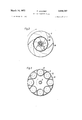
- FIG. 1 is a vertical section through an apparatus for making concrete tubes comprising a radially acting tube forming unit or pressing head which is provided with an impeller disc constructed and arranged in accordance with the invention.
- FIGS. 2 and 3 are respective sectional views taken along the lines IIII and 1IIIIH respectively of FIG. 1.
- FIG. 4 is a diagrammatic view of the male mold lifting means in accordance with the invention.
- the apparatus comprises an outer or female mold 1 determining the outer dimensions of the tubes to be produced and having in its interior cavity a tube forming unit 2 or pressing head.
- This tube forming unit 2 includes an impeller or distributor disc 3 and a pressing device 4 in the form of a roller smoothing piston unit.
- the pressing device 4 is connected with a shaft 5 which is driven by means of a gear wheel 7 attached to its upper end and driven in turn by a pin ion 6.
- a smooth ing piston or plunger 8 At the bottom end of the shaft 5 there is a smooth ing piston or plunger 8 with a sheet metal part 9 which is mounted in the manner of a flange and can be replaced when worn.
- Attached to an upper disc 10 of the smoothing piston 8, I provide eccentric bolts 11 carrying rollers 12 by means of sealed ball bearings. The upper ends of the rollers 12 are covered by a piece of sheet metal 13.
- a hollow shaft 16 is carried on shaft 5 by means of roller element bearings 14 and 15. This hollow shaft 16 is driven by means of a pinion 18 which meshes with a gear wheel 17 fixed at the upper end of the shaft 16. At the bottom end of the latter the distributor or impeller 3 is fixed. It comprises two frusto-conical discs 19 and 20. The lower annular disc 19 is directly connected with the shaft 16 while the upper annular disc 20 is connected to the lower disc 19 by means of impeller blades 21 which follow spiral curves as shown in FIG. 2. The upper disc 20 has additional impeller blades 22 mounted on it.
- the lower outer edge of the impeller 3, that is to say the lower outer edge of the disc 19 is located immediately above the pressing device 4 and is consequentially situated closely adjacent the rollers 12.
- the frusto-conical discs extend downwards and outwards away from the axis of the two shafts 5, 16.
- FIG. 4 shows the drive arrangement of the pressing device 4 including means for controlling lifting.
- the lifting means for the pressing device consists of a piston and cylinder ram unit 23.
- the rod of the piston 24 of this unit is connected by means of a chain 25 or the like, which passes over pulleys 26 and 27, with the pressing device. If oil under pressure is supplied by a pump 28 into the upper chamber of the ram unit 23, the piston 24 moves downwards so that there occurs lifting of the pressing device and the impeller.
- I For driving the pressing device 4, I provide a transmission 29 and a driving hydraulic motor 30 which is preferably arranged to run at a constant speed.
- This motor is supplied by a pump 32 with oil from an oil reservoir or container 33.
- a pressure oil duct 31 is connected by means of a branch or control duct 31 with a regulating valve 34.
- This valve 34 is arranged to control flow of pressure oil along a branch duct 35 which is connected with the pump 28 and the upper piston space of the ram unit 23.
- the duct 35 leads to an oil reservoir or container 37.
- the control or regulating valve 34 has a plunger which can move so as to alter to a greater or lesser extent the degree of overlap of cooperating valve ports in the path of oil along the duct 35 to the oil container 37.
- This plunger is acted upon, on the one hand, by the pressure of the oil supplied through the duct 31 and the branch duct 31, while on the other hand it is acted upon by a spring 38 whose force can be adjusted by setting a screw, not shown.
- the amount of response of the plunger to the pressure prevailing in the duct 31 (transmitted via duct 31) can be varied.
- the apparatus for producing concrete tubes operates as follows.
- Unset concrete supplied to the apparatus passes through the annular gap between the upper edge 20a of the frusto-conical disc 20 and the shaft 16 so as to be acted upon by the blades 21, or alternatively is impelled by the blades 22 on top of the frusto-conical disc 20. Owing to the rotation of the impeller 3 the concrete is impelled centrifugally outwards by the blades 21 and 22 against the female mold 1.
- the supply pressure p is also proportional to the degree of compaction of the tube concrete. If while the tube forming unit is being moved upwards by the descending piston 24 of the ram, the rate of supply of concrete is, for example, reduced, the torque M of the hydraulic motor 30 is also reduced. Consequently the pressure p in the duct 31 is reduced together with the pressure in duct 31'. The piston or plunger of the regulating valve 34 is moved upwards by spring 38 and decreases the throttling action in the duct 35. As a result a larger amount of the oil under pressure from pump 28 can pass to the oil container 37 instead of passing to the upper part of the ram unit 23 through the duct 36.
Landscapes
- Engineering & Computer Science (AREA)
- Manufacturing & Machinery (AREA)
- Chemical & Material Sciences (AREA)
- Ceramic Engineering (AREA)
- Mechanical Engineering (AREA)
- Manufacturing Of Tubular Articles Or Embedded Moulded Articles (AREA)
- On-Site Construction Work That Accompanies The Preparation And Application Of Concrete (AREA)
Applications Claiming Priority (1)
| Application Number | Priority Date | Filing Date | Title |
|---|---|---|---|
| AT278168A AT277035B (de) | 1968-03-20 | 1968-03-20 | Verfahren und Einrichtung zur Herstellung von Zementrohren |
Publications (1)
| Publication Number | Publication Date |
|---|---|
| US3649727A true US3649727A (en) | 1972-03-14 |
Family
ID=3540188
Family Applications (2)
| Application Number | Title | Priority Date | Filing Date |
|---|---|---|---|
| US806111A Expired - Lifetime US3649727A (en) | 1968-03-20 | 1969-03-11 | Making concrete tubes |
| US00188823A Expired - Lifetime US3746494A (en) | 1968-03-20 | 1971-10-13 | Apparatus for making concrete tubes |
Family Applications After (1)
| Application Number | Title | Priority Date | Filing Date |
|---|---|---|---|
| US00188823A Expired - Lifetime US3746494A (en) | 1968-03-20 | 1971-10-13 | Apparatus for making concrete tubes |
Country Status (5)
| Country | Link |
|---|---|
| US (2) | US3649727A (de) |
| AT (1) | AT277035B (de) |
| CH (1) | CH481732A (de) |
| DK (1) | DK121847B (de) |
| FR (1) | FR2004303A1 (de) |
Cited By (7)
| Publication number | Priority date | Publication date | Assignee | Title |
|---|---|---|---|---|
| US4311632A (en) * | 1980-06-16 | 1982-01-19 | Hiraoka Giken Kogyo Co., Ltd. | Process for molding a concrete pipe |
| US4336013A (en) * | 1979-05-16 | 1982-06-22 | Kerr Concrete Pipe Company | Apparatus for forming concrete articles of uniform density |
| US4360331A (en) * | 1980-06-16 | 1982-11-23 | Hiraoka Giken Kogyo Co., Ltd. | Apparatus for molding a concrete pipe |
| US4690631A (en) * | 1986-03-06 | 1987-09-01 | Hydrotile Machinery Company | Packerhead with elastic rollers |
| US4957424A (en) * | 1989-03-13 | 1990-09-18 | Hydrotile Machinery Company | Concrete pipe making machine |
| US5051223A (en) * | 1988-03-08 | 1991-09-24 | Gregor Kern | Method for the production of concrete pipes |
| US5059067A (en) * | 1989-11-01 | 1991-10-22 | Mccoy James M | Method for forming a curved interior profile to a cementitious material |
Families Citing this family (12)
| Publication number | Priority date | Publication date | Assignee | Title |
|---|---|---|---|---|
| US4340553A (en) * | 1978-12-29 | 1982-07-20 | Hydrotile Machinery Company | Machine and method for making concrete product |
| ATE999T1 (de) * | 1979-03-08 | 1982-05-15 | Georg Fischer Aktiengesellschaft | Einrichtung zum schleuderpressen eines betonrohres mit unten liegender muffe. |
| US4406605A (en) * | 1979-05-16 | 1983-09-27 | Kerr Concrete Pipe Company | Apparatus for forming concrete pipe of uniform density including control means to vary feed rate of concrete/aggregate as function of packerhead torque |
| US4407648A (en) * | 1980-09-18 | 1983-10-04 | Hydrotile Machinery Company | Counter rotating packerhead assembly |
| US4540539A (en) * | 1982-12-21 | 1985-09-10 | International Pipe Machinery Corp. | Method and apparatus for production of concrete pipe by the packerhead method |
| US4639342A (en) * | 1984-06-11 | 1987-01-27 | Hydrotile Machinery Company | Combined concrete feed and packerhead lift control |
| DE3805720A1 (de) * | 1988-02-24 | 1989-09-07 | Prinzing Georg Gmbh Co Kg | Verfahren zum herstellen von betonteilen und einrichtung zur durchfuehrung des verfahrens |
| US5080571A (en) * | 1990-02-28 | 1992-01-14 | International Pipe Machinery Corporation | Packerhead assembly |
| DK71391D0 (da) * | 1991-04-19 | 1991-04-19 | Pedershaab Maskinfabrik As | Maskine til i et formsystem med fordelerhjul vertikalt at stoebe roer af beton eller lignende materiale |
| DE4322785A1 (de) * | 1992-08-17 | 1995-01-19 | Zueblin Ag | Verfahren zur Herstellung von Betonrohren und Vorrichtung zur Durchführung des Verfahrens |
| US6106749A (en) * | 1997-01-08 | 2000-08-22 | Adly; Tarek A. | Method and machine for making concrete pipe |
| DE50101337D1 (de) * | 2001-11-02 | 2004-02-19 | Iff Weimar | Formgebungseinrichtung zur Herstellung von Rohren aus Betongemenge |
Family Cites Families (7)
| Publication number | Priority date | Publication date | Assignee | Title |
|---|---|---|---|---|
| US1616816A (en) * | 1927-02-08 | Packer head eor pipe-molding machines | ||
| US1502509A (en) * | 1923-10-03 | 1924-07-22 | Samuel G Mactarnaghan | Concrete-pipe-forming machine |
| US2178015A (en) * | 1937-12-08 | 1939-10-31 | Brunetti Valerio | Apparatus for making pipe |
| US2193286A (en) * | 1938-11-21 | 1940-03-12 | Due Jay H La | Roller packer for concrete tile |
| US2641818A (en) * | 1948-09-04 | 1953-06-16 | Hector X Eschenbrenner | Apparatus for molding concrete pipe |
| US3096556A (en) * | 1961-06-23 | 1963-07-09 | Randell C Woods | Concrete pipe forming apparatus |
| US3276091A (en) * | 1964-04-20 | 1966-10-04 | Charles B Pausch | Roller head for cement pipe forming |
-
1968
- 1968-03-20 AT AT278168A patent/AT277035B/de not_active IP Right Cessation
-
1969
- 1969-03-11 US US806111A patent/US3649727A/en not_active Expired - Lifetime
- 1969-03-18 CH CH404869A patent/CH481732A/de not_active IP Right Cessation
- 1969-03-19 DK DK149969AA patent/DK121847B/da unknown
- 1969-03-19 FR FR6907914A patent/FR2004303A1/fr not_active Withdrawn
-
1971
- 1971-10-13 US US00188823A patent/US3746494A/en not_active Expired - Lifetime
Cited By (7)
| Publication number | Priority date | Publication date | Assignee | Title |
|---|---|---|---|---|
| US4336013A (en) * | 1979-05-16 | 1982-06-22 | Kerr Concrete Pipe Company | Apparatus for forming concrete articles of uniform density |
| US4311632A (en) * | 1980-06-16 | 1982-01-19 | Hiraoka Giken Kogyo Co., Ltd. | Process for molding a concrete pipe |
| US4360331A (en) * | 1980-06-16 | 1982-11-23 | Hiraoka Giken Kogyo Co., Ltd. | Apparatus for molding a concrete pipe |
| US4690631A (en) * | 1986-03-06 | 1987-09-01 | Hydrotile Machinery Company | Packerhead with elastic rollers |
| US5051223A (en) * | 1988-03-08 | 1991-09-24 | Gregor Kern | Method for the production of concrete pipes |
| US4957424A (en) * | 1989-03-13 | 1990-09-18 | Hydrotile Machinery Company | Concrete pipe making machine |
| US5059067A (en) * | 1989-11-01 | 1991-10-22 | Mccoy James M | Method for forming a curved interior profile to a cementitious material |
Also Published As
| Publication number | Publication date |
|---|---|
| AT277035B (de) | 1969-12-10 |
| DK121847B (da) | 1971-12-06 |
| US3746494A (en) | 1973-07-17 |
| CH481732A (de) | 1969-11-30 |
| FR2004303A1 (de) | 1969-11-21 |
Similar Documents
| Publication | Publication Date | Title |
|---|---|---|
| US3649727A (en) | Making concrete tubes | |
| US4119025A (en) | Method and apparatus for conveying particulate material | |
| US4186658A (en) | Apparatus for conveying particulate material | |
| US4340553A (en) | Machine and method for making concrete product | |
| US3608138A (en) | Apparatus for rolling and forming articles | |
| DK144864B (da) | Fremgangsmaade til fremstilling af et roerformet legeme af cementholdigt materiale der er armeret med glasfibertraade og apparat til brug ved udoevelse af fremgangsmaaden | |
| US4407648A (en) | Counter rotating packerhead assembly | |
| CN106638558A (zh) | 土木工程用高压喷射注浆装置 | |
| DE2129177A1 (de) | Verfahren und Vorrichtung zum Aufbringen einer feuerfesten Ausfutterung auf die Innenwand von metallurgischen Gefäßen | |
| JPH0118826B2 (de) | ||
| CA1062423A (en) | Extrusion | |
| US4253814A (en) | Packerhead and core control system | |
| CN208629648U (zh) | 一种直立式滚压成型机 | |
| US3268959A (en) | Method and apparatus for vertical casting of hollow metalic bodies | |
| CN108582418A (zh) | 一种直立式滚压成型机及陶瓷坯体滚压成型的方法 | |
| US2309376A (en) | Apparatus for conditioning fiber bearing materials | |
| US2961017A (en) | Common drive for raising the top feed rollers and advancing the rollers of frame saws | |
| CA1091597A (en) | Method and device in connection with a pressure cyclone | |
| US2597811A (en) | Metal pouring apparatus for feeding molten metal into centrifugal molds | |
| US1802613A (en) | Centrifugal casting machine | |
| US2641818A (en) | Apparatus for molding concrete pipe | |
| US1625123A (en) | Device for the production of concrete pipes and especially for devices for applying the concrete | |
| US3307228A (en) | Continuous casting control method and apparatus | |
| US1620831A (en) | Charging device for tilting molds | |
| US2193286A (en) | Roller packer for concrete tile |