US3639846A - Tandem sampling controller using delayed operation of plural sampling gates - Google Patents
Tandem sampling controller using delayed operation of plural sampling gates Download PDFInfo
- Publication number
- US3639846A US3639846A US18649A US3639846DA US3639846A US 3639846 A US3639846 A US 3639846A US 18649 A US18649 A US 18649A US 3639846D A US3639846D A US 3639846DA US 3639846 A US3639846 A US 3639846A
- Authority
- US
- United States
- Prior art keywords
- signal
- sampling
- input
- sampler
- sampling trigger
- Prior art date
- Legal status (The legal status is an assumption and is not a legal conclusion. Google has not performed a legal analysis and makes no representation as to the accuracy of the status listed.)
- Expired - Lifetime
Links
- 238000005070 sampling Methods 0.000 title claims description 67
- 230000003111 delayed effect Effects 0.000 title description 3
- 239000003990 capacitor Substances 0.000 claims description 8
- 238000001914 filtration Methods 0.000 description 3
- 102100022704 Amyloid-beta precursor protein Human genes 0.000 description 1
- 101000823051 Homo sapiens Amyloid-beta precursor protein Proteins 0.000 description 1
- DZHSAHHDTRWUTF-SIQRNXPUSA-N amyloid-beta polypeptide 42 Chemical compound C([C@@H](C(=O)N[C@@H](C)C(=O)N[C@@H](CCC(O)=O)C(=O)N[C@@H](CC(O)=O)C(=O)N[C@H](C(=O)NCC(=O)N[C@@H](CO)C(=O)N[C@@H](CC(N)=O)C(=O)N[C@@H](CCCCN)C(=O)NCC(=O)N[C@@H](C)C(=O)N[C@H](C(=O)N[C@@H]([C@@H](C)CC)C(=O)NCC(=O)N[C@@H](CC(C)C)C(=O)N[C@@H](CCSC)C(=O)N[C@@H](C(C)C)C(=O)NCC(=O)NCC(=O)N[C@@H](C(C)C)C(=O)N[C@@H](C(C)C)C(=O)N[C@@H]([C@@H](C)CC)C(=O)N[C@@H](C)C(O)=O)[C@@H](C)CC)C(C)C)NC(=O)[C@H](CC=1C=CC=CC=1)NC(=O)[C@@H](NC(=O)[C@H](CC(C)C)NC(=O)[C@H](CCCCN)NC(=O)[C@H](CCC(N)=O)NC(=O)[C@H](CC=1N=CNC=1)NC(=O)[C@H](CC=1N=CNC=1)NC(=O)[C@@H](NC(=O)[C@H](CCC(O)=O)NC(=O)[C@H](CC=1C=CC(O)=CC=1)NC(=O)CNC(=O)[C@H](CO)NC(=O)[C@H](CC(O)=O)NC(=O)[C@H](CC=1N=CNC=1)NC(=O)[C@H](CCCNC(N)=N)NC(=O)[C@H](CC=1C=CC=CC=1)NC(=O)[C@H](CCC(O)=O)NC(=O)[C@H](C)NC(=O)[C@@H](N)CC(O)=O)C(C)C)C(C)C)C1=CC=CC=C1 DZHSAHHDTRWUTF-SIQRNXPUSA-N 0.000 description 1
- 230000008878 coupling Effects 0.000 description 1
- 238000010168 coupling process Methods 0.000 description 1
- 238000005859 coupling reaction Methods 0.000 description 1
- 238000010586 diagram Methods 0.000 description 1
- 230000000694 effects Effects 0.000 description 1
- 230000001960 triggered effect Effects 0.000 description 1
Images
Classifications
-
- H—ELECTRICITY
- H03—ELECTRONIC CIRCUITRY
- H03L—AUTOMATIC CONTROL, STARTING, SYNCHRONISATION OR STABILISATION OF GENERATORS OF ELECTRONIC OSCILLATIONS OR PULSES
- H03L7/00—Automatic control of frequency or phase; Synchronisation
- H03L7/06—Automatic control of frequency or phase; Synchronisation using a reference signal applied to a frequency- or phase-locked loop
- H03L7/16—Indirect frequency synthesis, i.e. generating a desired one of a number of predetermined frequencies using a frequency- or phase-locked loop
-
- H—ELECTRICITY
- H03—ELECTRONIC CIRCUITRY
- H03D—DEMODULATION OR TRANSFERENCE OF MODULATION FROM ONE CARRIER TO ANOTHER
- H03D3/00—Demodulation of angle-, frequency- or phase- modulated oscillations
- H03D3/02—Demodulation of angle-, frequency- or phase- modulated oscillations by detecting phase difference between two signals obtained from input signal
- H03D3/24—Modifications of demodulators to reject or remove amplitude variations by means of locked-in oscillator circuits
- H03D3/241—Modifications of demodulators to reject or remove amplitude variations by means of locked-in oscillator circuits the oscillator being part of a phase locked loop
Definitions
- an additional sampler is connected to sample the output of a preceding sampler in order to obviate the need for extensive filtering typically required to smooth out the fluctuations normally present in the output of a single sampler.
- the output of the second sampler thus contains the desired steady signal component and substantially no signal variations. Sampler feed-through which may contribute signal variation at the output of the second sampler may be compensated for by capacitive balancing circuitry.
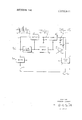
- the drawing is a block diagram of the tandem sampling controller of the present invention.
- a signal sampler 9 is connected to receive an applied signal on line 11 and a sampling trigger signal from pulse generator 13 for producing a sample pulse having an amplitude substantially equal to the amplitude of the applied signal at the instant the pulse generator 13 produces a sampling trigger signal.
- the sample pulse is applied to a pulse stretcher or amplitude-storing circuit including a capacitor 15 and is also applied to the input of another sampler 17.
- the output of sampler 17 is also applied to a pulse stretcher or amplitude-storing circuit including a capacitor 19.
- Samplers 9 and I7 are conventional elements described in the literature (see, for example, US. Pat. No. 3,241,076, entitled SIGNAL SAMPLING CIRCUITS etc., issued on Mar. 15, 1966, to K. B.'Magleby and W. M. Grove). These samplers typically produce sample pulses that are less than one microsecond wide e.g., t 1 sec.) so that after one microsecond, the amplitude-storing circuit at the output of a sampler retains the final value of a sample pulse until the next sample pulse is produced.
- the resulting waveform present at the amplitude-storing circuit following the first sampler 9 thus contains in the width of a sample pulse (i.e., within t,,) a portion of the waveshape of the applied signal appearing onconductor 11.
- the final value of the sampled waveshape at the end of the sampling period establishes the baseline value which is stored until the next sample pulse is produced, as shown in the drawing.
- the disadvantage encountered with sampled and stored signal of this type is that the signal variations about the baseline value may introduce undesirable effects when used as a control signal, say, for a signal-controlled oscillator. Such signal variations may produce undesirable frequency modulations and, accordingly, would have to be well filtered before being used as a control signal.
- delay network 21 which may be a delay line or conventional multivibrator circuit applies the sample trigger signal from pulse generator 13 to the second sampler 17 at a selected delay time after the sample trigger signal is'applied to the first sampler 9.
- this delay time is about 4 microseconds to assure that sampler 17 samples the baseline value of the stored output well after signal variations due to operation of sampler 9 have passed.
- the stored output appearing on the amplitude-storing circuit including capacitor 19 ideally should have a steady value indicative of the stored baseline value appearing on the amplitude-storing circuit associated with the first sampler 9.
- the signal applied to the first sampler 9 is the modulation product of a variable frequency input f,.,,,. and a local signal frequency 29 which are mixed in mixer 31.
- the local oscillator 33 is connected to receive the control signal at output 23 for producing a signal frequency representative of the amplitude of the applied control signal,
- the pulse generator in this embodiment 13 may be triggered at a selected rate determined by an applied reference frequency f,,,,. Accordingly, the illustrated embodiment of the present invention is capable of controlling the local oscillator 33 to produce an output signal frequency 29 which is always separated in frequency from the variable frequency input f,.,,,. by the value of the reference frequency f,,.,.
- I 1 Tandem sampling controller apparatus comprising: first and second samplers, each having an output and a signal input and a sampling trigger input for producing at the output a sample pulse having an amplitude representative of the amplitude of a signal applied to the signal input at the time a sampling trigger signal is applied to the sampling trigger input thereof; first and second signal storing means connected respectively '.to the outputs of the first and second samplers for storing the amplitude of sample pulses between sampling times; sample trigger generating means connected to the sampling Ztrigger input of the first sampler for applying sampling trigger signals thereto at selected sampling times; means connecting the signal input of the second sampler to receive the stored sample pulses from the first signal storing means; delay means connected to the sample trigger generating means for applying a sampling trigger signal to the sampling trigger input of the second sampler a predetermined time interval after each sampling trigger signal applied to
- said circuit means includes a signal mixer having an input connected to receive the output frequency from said oscillator and having another input connected to receive an applied signal frequency and having an output connected to the signal input of the first sampler for applying thereto a modulation product of signal frequencies applied to the inputs of said signal mixer.
- Tandem sampling controller apparatus comprising: first and second samplers, each having an output and a signal input and .a sampling trigger input for producing at the output a sample pulse having an amplitude representative of the amplitude of a signal applied to the signal input at the time a sampling trigger signal is applied to the sampling trigger input thereof;
- first and second signal storing means connected respectively to the outputs of the first and second samplers for storing the amplitude of sample pulses between sampling times;
- circuit means connected to the signal input for applying thereto a signal to be sampled
- sample trigger generating means connected to the sampling trigger input of the first sampler for applying sampling trigger signals thereto at selected sampling times;
- delay means connected to the sample trigger generating means for applying a sampling trigger signal to the sampling trigger input of the second sampler a predetermined time interval after each sampling trigger signal applied to the sampling trigger input of the first sampler;
- compensating means including a capacitor and an inverting amplifier having an input connected to receive sampling trigger signals from said delay means and an output connected through said capacitor to said second signal storing means for applying compensating signal thereto to decrease signal perturbations appearing at the second signal storing means;
- a utilization circuit connected to respond to the stored signal received from the second signal storing means.
Landscapes
- Engineering & Computer Science (AREA)
- Power Engineering (AREA)
- Amplitude Modulation (AREA)
- Networks Using Active Elements (AREA)
- Measuring Frequencies, Analyzing Spectra (AREA)
- Measuring Phase Differences (AREA)
- Stabilization Of Oscillater, Synchronisation, Frequency Synthesizers (AREA)
- Manipulation Of Pulses (AREA)
Applications Claiming Priority (1)
| Application Number | Priority Date | Filing Date | Title |
|---|---|---|---|
| US1864970A | 1970-03-11 | 1970-03-11 |
Publications (1)
| Publication Number | Publication Date |
|---|---|
| US3639846A true US3639846A (en) | 1972-02-01 |
Family
ID=21789050
Family Applications (1)
| Application Number | Title | Priority Date | Filing Date |
|---|---|---|---|
| US18649A Expired - Lifetime US3639846A (en) | 1970-03-11 | 1970-03-11 | Tandem sampling controller using delayed operation of plural sampling gates |
Country Status (5)
| Country | Link |
|---|---|
| US (1) | US3639846A (enExample) |
| JP (1) | JPS5112265B1 (enExample) |
| DE (1) | DE2061227B2 (enExample) |
| FR (1) | FR2084415A5 (enExample) |
| GB (1) | GB1329446A (enExample) |
Cited By (1)
| Publication number | Priority date | Publication date | Assignee | Title |
|---|---|---|---|---|
| US4117409A (en) * | 1975-12-11 | 1978-09-26 | Hughes Aircraft Company | Signal sampling system |
Families Citing this family (1)
| Publication number | Priority date | Publication date | Assignee | Title |
|---|---|---|---|---|
| US4229759A (en) * | 1978-08-23 | 1980-10-21 | Rca Corporation | Signal detector including sample and hold circuit with reduced offset error |
Citations (3)
| Publication number | Priority date | Publication date | Assignee | Title |
|---|---|---|---|---|
| US3011129A (en) * | 1959-08-10 | 1961-11-28 | Hewlett Packard Co | Plural series gate sampling circuit using positive feedback |
| US3314014A (en) * | 1963-02-21 | 1967-04-11 | Plessey Uk Ltd | Frequency comparing systems |
| US3414818A (en) * | 1964-06-03 | 1968-12-03 | Int Standard Electric Corp | Companding pulse code modulation system |
-
1970
- 1970-03-11 US US18649A patent/US3639846A/en not_active Expired - Lifetime
- 1970-10-07 GB GB4778570A patent/GB1329446A/en not_active Expired
- 1970-12-12 DE DE19702061227 patent/DE2061227B2/de active Pending
-
1971
- 1971-03-10 FR FR7108253A patent/FR2084415A5/fr not_active Expired
- 1971-03-11 JP JP46013297A patent/JPS5112265B1/ja active Pending
Patent Citations (3)
| Publication number | Priority date | Publication date | Assignee | Title |
|---|---|---|---|---|
| US3011129A (en) * | 1959-08-10 | 1961-11-28 | Hewlett Packard Co | Plural series gate sampling circuit using positive feedback |
| US3314014A (en) * | 1963-02-21 | 1967-04-11 | Plessey Uk Ltd | Frequency comparing systems |
| US3414818A (en) * | 1964-06-03 | 1968-12-03 | Int Standard Electric Corp | Companding pulse code modulation system |
Cited By (1)
| Publication number | Priority date | Publication date | Assignee | Title |
|---|---|---|---|---|
| US4117409A (en) * | 1975-12-11 | 1978-09-26 | Hughes Aircraft Company | Signal sampling system |
Also Published As
| Publication number | Publication date |
|---|---|
| FR2084415A5 (enExample) | 1971-12-17 |
| GB1329446A (en) | 1973-09-05 |
| DE2061227B2 (de) | 1973-09-06 |
| JPS5112265B1 (enExample) | 1976-04-17 |
| DE2061227A1 (de) | 1971-12-02 |
Similar Documents
| Publication | Publication Date | Title |
|---|---|---|
| US4806878A (en) | Phase comparator lock detect circuit and a synthesizer using same | |
| DE3538856C2 (de) | Digitaler Phasendetektor | |
| US3895294A (en) | Phase change measuring circuit | |
| GB1266236A (enExample) | ||
| GB1325219A (en) | Variable frequency oscillator systems | |
| GB959387A (en) | Frequency stabilised signal generating circuits | |
| US3943460A (en) | Frequency conversion system | |
| GB1299023A (en) | Improvements in or relating to spectrum analysers | |
| GB1445625A (en) | Generator with decade frequency adjustment | |
| US3639846A (en) | Tandem sampling controller using delayed operation of plural sampling gates | |
| GB1310410A (en) | Method for fourier analysis of interference signals | |
| GB788114A (en) | Improvements relating to frequency and phase control systems | |
| DE4325896C2 (de) | Phasenstartbare Taktgebervorrichtung | |
| GB1141350A (en) | Phase lock circuit | |
| US3086080A (en) | Self-timed regenerative repeater for pcm | |
| US3716785A (en) | Digitally controlled wave analyzer | |
| US3675136A (en) | Apparatus for use in measuring phase dispersion produced by apparatus or a system | |
| GB977474A (en) | Tone frequency control means for keyed filtered systems | |
| GB1015283A (en) | Frequency synthesizer for single sideband communications | |
| GB1229376A (enExample) | ||
| US3416087A (en) | Phase-locked signal sampling circuit with adaptive search circuit | |
| US3369185A (en) | Rc correlator circuit for synchronous signal detection | |
| KR890002850A (ko) | 저역 색신호 변환장치 | |
| US3147440A (en) | Cross-modulation detector means tuned to local oscillator frequency | |
| US3835398A (en) | Clock pulse regenerator |