US3628443A - Adjustable air-direction means for a conditioner - Google Patents
Adjustable air-direction means for a conditioner Download PDFInfo
- Publication number
- US3628443A US3628443A US883568A US3628443DA US3628443A US 3628443 A US3628443 A US 3628443A US 883568 A US883568 A US 883568A US 3628443D A US3628443D A US 3628443DA US 3628443 A US3628443 A US 3628443A
- Authority
- US
- United States
- Prior art keywords
- louver
- vanes
- air
- conditioner
- pivot
- Prior art date
- Legal status (The legal status is an assumption and is not a legal conclusion. Google has not performed a legal analysis and makes no representation as to the accuracy of the status listed.)
- Expired - Lifetime
Links
- 230000003014 reinforcing effect Effects 0.000 claims description 8
- 239000004033 plastic Substances 0.000 claims description 6
- 230000003750 conditioning effect Effects 0.000 claims description 5
- 238000007599 discharging Methods 0.000 claims description 5
- 239000012858 resilient material Substances 0.000 claims description 2
- 238000011144 upstream manufacturing Methods 0.000 claims description 2
- 238000004378 air conditioning Methods 0.000 description 2
- 238000001816 cooling Methods 0.000 description 2
- 230000001143 conditioned effect Effects 0.000 description 1
- 238000001746 injection moulding Methods 0.000 description 1
- 239000002184 metal Substances 0.000 description 1
- 239000002991 molded plastic Substances 0.000 description 1
Images

Classifications
-
- F—MECHANICAL ENGINEERING; LIGHTING; HEATING; WEAPONS; BLASTING
- F24—HEATING; RANGES; VENTILATING
- F24F—AIR-CONDITIONING; AIR-HUMIDIFICATION; VENTILATION; USE OF AIR CURRENTS FOR SCREENING
- F24F13/00—Details common to, or for air-conditioning, air-humidification, ventilation or use of air currents for screening
- F24F13/08—Air-flow control members, e.g. louvres, grilles, flaps or guide plates
- F24F13/082—Grilles, registers or guards
Definitions
- Lind ABSTRACT Air-direction device for adjustably redirecting air from an air conditioner, including two unitary louvers each having pitched air-directing vanes, means mounting one of the louvers on the conditioner to pivot about an axis parallel generally to its vanes for adjustably redirecting the air in planes parallel to the pivot axis, and means releasably mounting the second louver on the first louver in either of two positions where the vanes cross and in series with the air flow so that its vanes redirect the air in planes: transverse to the pivot aXlS.
- a typical room air conditioner for example, has interconnected walls which define an outlet opening for discharging conditioned air along a generally given path. Depending on the particular demands of cooling and the location of the conditioner relative to the room, it frequently is desirable to redirect the air somewhat from this path. To accommodate this, a louver control is used which frequently involves many separate parts quite expensive to fabricate and difficult to assemble, and quite susceptible to damage during use.
- This invention relates to an air direction device suitable for adjustably directing air from a given path in any number of rightward, leftward, upward or downward inclinations.
- a main object of this invention is to provide an adjustable air direction device for redirecting air from a given direction in any of a number of ways as might be desired, and moreover to provide such a device which is economically manufactured and easily assembled and which is durable in use.
- a more specific object of this invention is to provide an air direction device having two and possibly three separate and unitary louvers each formed with a plurality of pitched vanes, where one louver is pivotally mounted so that its vanes can be adjustable inclined as desired to redirect air in planes parallel to the pivot axis and where the other louver can be selectively mounted on the first louver in any of several orientations where the vanes cross for further redirecting the air in planes transverse to the pivot axis.
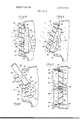
- FIG. 1 is a perspective view of a typical air-conditioning unit having a preferred embodiment of the subject air direction device incorporated therein;
- FIG. 2 is a perspective view enlarged somewhat from that shown in FIG. 1, showing the directional device more in detail and its relationship with the conditioning unit;
- FIG. 3 is a perspective view of one of the louvers which forms the air direction device disclosed herein;
- FIGS. 4, 5 and 6 are sectional views as seen generally from line 44 in FIG. 1 showing possible positions of the air direction device.
- FIG. 7 is a sectional view as seen generally from line 7-7 in FIG. 4.
- a typical window air-conditioning unit 10 having a casing 12 including an air discharge opening 14 and an air return opening 16.
- Appropriate blower means are provided in the casing to move air over a cooling evaporator coil (not shown) and subsequently discharge it chilled from the opening 14. Since opposed horizontal walls 18 and a pair of interconnecting vertical walls 20 define the discharge opening, the air would normally be discharged in a direction generally parallel to these walls.
- the particular air-directing device shown includes a first louver 24 and two second louvers 26.
- Each louver has a plurality of pitched vanes, and the louvers are mounted adjacent one another in series restriction with the air discharge from the conditioner opening 14.
- airflow from the opening is influenced by the presence of the louver vanes and is redirected accordingly.
- the first louver 24 has a plurality of generally parallel horizontal vanes 30 extended between opposed vertical end pieces 32. Reinforcing ribs 34 of narrow cross section and thereby low air resistance connected across the vanes add rigidity to the louver.
- the vanes 30 on the first louver 24 preferably are pitched upwardly slightly of the order of to 35 relative to the usual inlet direction of airflow as the louver is mounted perpendicular to the airflow (See FIG. 4).
- the first louver 24 is mounted on the conditioning unit 10 within the discharge opening 14 and is sized to completely cover the opening although there is sufficient clearance to accommodate pivotal movement.
- opposed pins 36 extend from the vertical walls of the conditioner opening a pivot edge 38 extends along the upper horizontal opening wall 18.
- the upper ends of the two end reinforcing ribs 34 have concave notches which are positioned on the pivot edge 38 and held thereagainst resiliently by the: pins 36 being received in slotted openings 40 in the end pieces 32.
- the upper surface 42 of each slot is notched so that it cooperates as a detent with the pin to hold the first louver in any rotatably adjusted position (See FIGS. 4 and 5). Air passing the vanes is thus redirected within planes generally parallel to the rotational axis (edge 38) of the first louver.
- Each second louver 26 likewise has a plurality of vanes 48 extended between top and bottom pieces 50.
- Opposing flanges 52 are formed from the outer edges of the endpiece 53 and are adapted to fit behind appropriate guides or nubs 54 formed adjacent the rear side of the first louver vanes 30 from the endpieces 32.
- the second louver 26 can be removably mounted on the first louver 24 with the flanges 52 being slid beneath the guides 54 (See FIG. 6) to place the first and second louver vanes in series restriction to the normal air discharge.
- the rearwardly formed lugs 58 formed on the webs 34 hold the louvers 26 at the proper height relative to louver 24.
- the vanes 48 on the second louver device 26 are likewise pitched slightly out of parallel with the inlet airflow of the order of 15 to 35 and are preferably parallel to one another.
- the second louver 26 is otherwise symmetric so that it can be positioned relative to the first louver device in either of two orientations where the vanes cross. In other words, the air can be directed along planes transverse to the pivot axis of the first louver either to the right or to the left of the vent opening.
- the air discharge can be adjusted in a vertical direction along planes parallel to the first louver pivot axis by pivoting the first louver 24 about the pivot edge 38, and further can be adjusted in horizontal directions along planes transverse to the pivot axis by the selective positioning of the second louvers 26 on the first louver 24.
- both second louvers oriented in the same manner for directing the air either predominantly rightwardly or leftwardly, or it is possible to orient the second louvers oppositely for increased lateral air distribution, or it is possible to omit either or both of the second louvers so the air is directed only by the first louver.
- first and the second louvers are each formed as a generally unitary device having no moving parts.
- each can be of plastic readily fabricated as by injection-molding in an economical manner. Once fabricated, each is quite durable and lightweight. Furthermore, because only three pieces form the actual grill assembly, it can be readily assembled to itself and further in place within the conditioning unit.
- the normal flexibility of the plastic louver 24 permits it to be snapped in place over the pins and pivot edge of the conditioner.
- the pins 36 and pivot edge 38 on the conditioner can be easily added to or formed integrally therewith, which typically would be formed of sheet metal or injection-molded plastic.
- the second louvers 26 an be slid in place on or removed from the first louver 24 when the first louver is partially or totally removed from the conditioner (See FIG. 6).
- An adjustable air direction device for a conditioner having interconnected walls defining an opening for discharging air in a given direction
- the combination comprising first and second louvers each having a plurality of spaced stationary vanes, means to pivot said first louver to the conditioning device to extend substantially completely cross the opening and be adjustable about an axis generally parallel to its vanes for adjusting said air discharge in planes generally parallel to said pivot axis, means for removably mounting the second louver on and adjacent the first louver in any of several positions where the louver vanes cross, and the second louver vanes being pitched slightly out of parallel to the given air discharge as mounted operable thereby to redirect the air in planes generally transverse to said pivot axis
- said pivot means for the first louver includes cooperating edge contact between the first louver and one of the opening walls along a line parallel to the pivot axis and cooperating pin and arcuately extended detent means between the first louver and two other opposing opening walls, wherein aid pivot means edge-contact for the first louver is offset from the pins
- An adjustable air direction device wherein the means for removably mounting the second louver on the first louver includes cooperating flange and guide elements between the louvers, and wherein the second louver is located upstream relative to the airflow of the first louver when mounted thereon.
- An adjustable air direction device for a conditioner having interconnected walls defining an opening for discharging air in a given direction, the combination comprising a first unitary louver having end elements and a plurality of spaced stationary vanes extended between the end elements and at least one intermediate reinforcing element disposed traversely of the vanes between the end elements, said first louver being made of a resilient material such as plastic where some lateral flexure of the vanes is possible without permanent deformation, means to mount the first louver to the conditioner to extend substantially completely across the opening and including cooperating pin and receiving means formed between the endpieces and one pair of opposed interconnected conditioner walls and an edge contact of said reinforcing element and one wall of the other pair of opposed interconnected conditioner walls, where lateral flexure of the vanes permits the end elements to be fitted relative to the one pair of conditioner walls while thereafter urging the edge contact of the reinforcing element against the said one wall which edge contact defines an axis about which the first louver can be pivoted for adjustment of the vanes and whereby the pin and receiving
- a second louver can be selectively used with or in combination with the first louver to further redirect the air in a direction transverse to the control provided by the first louver, the second louver being formed of a unitary piece having vanes inclined slightly relative to the plane of the louver device, and means for releasably mounting the second louver on and in adjacent facing relation to the first louver where the vanes of the respective louvers cross one another.
- louver device An adjustable air direction device according to claim 5, where the mounting means for the second louver includes cooperating flange and guide means between the louvers whereby the second louver device can be mounted on and carried by the first louver in either of at least two selectively positions particularly where the vanes are directed in oppositely pitched directions transversely of the first louver means.
Landscapes
- Engineering & Computer Science (AREA)
- Chemical & Material Sciences (AREA)
- Combustion & Propulsion (AREA)
- Mechanical Engineering (AREA)
- General Engineering & Computer Science (AREA)
- Air-Flow Control Members (AREA)
Abstract
Air-direction device for adjustably redirecting air from an air conditioner, including two unitary louvers each having pitched air-directing vanes, means mounting one of the louvers on the conditioner to pivot about an axis parallel generally to its vanes for adjustably redirecting the air in planes parallel to the pivot axis, and means releasably mounting the second louver on the first louver in either of two positions where the vanes cross and in series with the air flow so that its vanes redirect the air in planes transverse to the pivot axis.
Description
United States Patent [72] Inventor John Henning Albion, Mich. [21] Appl. No. 883,568 [22] Filed Dec. 9, 1969 [45] Patented Dec. 21,1971 [73] Assignee McGraw-Edison Company Elgin, Ill.
[54] ADJUSTABLE AIR-DIRECTION MEANS FOR A CONDITIONER 6 Claims, 7 Drawing Figs.
[52] US. Cl 98/121 [5|] Int. Cl F24f 13/08 [50] Field of Search 98/94, 107, 110, 12l;49/62, 39l; 62/262 [56] References Cited UNITED STATES PATENTS 2,987,891 6/1961 Boylan 98/1 10X 2,00l,80l 5/1935 Smith,Jr. 98/l2l X 2,842,199 7/1958 Pfeiffer 62/262 X 3,472,149 10/1969 Harrison 98/121 X FOREIGN PATENTS 930,716 7/1963 Great Britain 98/121 Primary Examiner-Meyer Perlin Assistant ExaminerW. C. Anderson Attorney-Charles F. Lind ABSTRACT: Air-direction device for adjustably redirecting air from an air conditioner, including two unitary louvers each having pitched air-directing vanes, means mounting one of the louvers on the conditioner to pivot about an axis parallel generally to its vanes for adjustably redirecting the air in planes parallel to the pivot axis, and means releasably mounting the second louver on the first louver in either of two positions where the vanes cross and in series with the air flow so that its vanes redirect the air in planes: transverse to the pivot aXlS.
ADJUSTABLE AIR-DIRECTION MEANS FOR A CONDITIONER A typical room air conditioner, for example, has interconnected walls which define an outlet opening for discharging conditioned air along a generally given path. Depending on the particular demands of cooling and the location of the conditioner relative to the room, it frequently is desirable to redirect the air somewhat from this path. To accommodate this, a louver control is used which frequently involves many separate parts quite expensive to fabricate and difficult to assemble, and quite susceptible to damage during use.
This invention relates to an air direction device suitable for adjustably directing air from a given path in any number of rightward, leftward, upward or downward inclinations.
A main object of this invention is to provide an adjustable air direction device for redirecting air from a given direction in any of a number of ways as might be desired, and moreover to provide such a device which is economically manufactured and easily assembled and which is durable in use.
A more specific object of this invention is to provide an air direction device having two and possibly three separate and unitary louvers each formed with a plurality of pitched vanes, where one louver is pivotally mounted so that its vanes can be adjustable inclined as desired to redirect air in planes parallel to the pivot axis and where the other louver can be selectively mounted on the first louver in any of several orientations where the vanes cross for further redirecting the air in planes transverse to the pivot axis. 7
These and other objects of this invention will be more fully understood after reviewing the following specification, the accompanying drawings forming a part thereof, wherein:
FIG. 1 is a perspective view of a typical air-conditioning unit having a preferred embodiment of the subject air direction device incorporated therein;
FIG. 2 is a perspective view enlarged somewhat from that shown in FIG. 1, showing the directional device more in detail and its relationship with the conditioning unit; and
FIG. 3 is a perspective view of one of the louvers which forms the air direction device disclosed herein;
FIGS. 4, 5 and 6 are sectional views as seen generally from line 44 in FIG. 1 showing possible positions of the air direction device; and
FIG. 7 is a sectional view as seen generally from line 7-7 in FIG. 4.
Referring now to FIG. I, a typical window air-conditioning unit 10 is shown having a casing 12 including an air discharge opening 14 and an air return opening 16. Appropriate blower means (not shown) are provided in the casing to move air over a cooling evaporator coil (not shown) and subsequently discharge it chilled from the opening 14. Since opposed horizontal walls 18 and a pair of interconnecting vertical walls 20 define the discharge opening, the air would normally be discharged in a direction generally parallel to these walls.
The particular air-directing device shown includes a first louver 24 and two second louvers 26. Each louver has a plurality of pitched vanes, and the louvers are mounted adjacent one another in series restriction with the air discharge from the conditioner opening 14. Thus, airflow from the opening is influenced by the presence of the louver vanes and is redirected accordingly.
Specifically, the first louver 24 has a plurality of generally parallel horizontal vanes 30 extended between opposed vertical end pieces 32. Reinforcing ribs 34 of narrow cross section and thereby low air resistance connected across the vanes add rigidity to the louver. The vanes 30 on the first louver 24 preferably are pitched upwardly slightly of the order of to 35 relative to the usual inlet direction of airflow as the louver is mounted perpendicular to the airflow (See FIG. 4).
The first louver 24 is mounted on the conditioning unit 10 within the discharge opening 14 and is sized to completely cover the opening although there is sufficient clearance to accommodate pivotal movement. In this regard, opposed pins 36 extend from the vertical walls of the conditioner opening a pivot edge 38 extends along the upper horizontal opening wall 18. The upper ends of the two end reinforcing ribs 34 have concave notches which are positioned on the pivot edge 38 and held thereagainst resiliently by the: pins 36 being received in slotted openings 40 in the end pieces 32. Preferably, the upper surface 42 of each slot is notched so that it cooperates as a detent with the pin to hold the first louver in any rotatably adjusted position (See FIGS. 4 and 5). Air passing the vanes is thus redirected within planes generally parallel to the rotational axis (edge 38) of the first louver.
Each second louver 26 likewise has a plurality of vanes 48 extended between top and bottom pieces 50. Opposing flanges 52 are formed from the outer edges of the endpiece 53 and are adapted to fit behind appropriate guides or nubs 54 formed adjacent the rear side of the first louver vanes 30 from the endpieces 32. Thus, the second louver 26 can be removably mounted on the first louver 24 with the flanges 52 being slid beneath the guides 54 (See FIG. 6) to place the first and second louver vanes in series restriction to the normal air discharge. The rearwardly formed lugs 58 formed on the webs 34 hold the louvers 26 at the proper height relative to louver 24. The vanes 48 on the second louver device 26 are likewise pitched slightly out of parallel with the inlet airflow of the order of 15 to 35 and are preferably parallel to one another. The second louver 26 is otherwise symmetric so that it can be positioned relative to the first louver device in either of two orientations where the vanes cross. In other words, the air can be directed along planes transverse to the pivot axis of the first louver either to the right or to the left of the vent opening.
The air discharge can be adjusted in a vertical direction along planes parallel to the first louver pivot axis by pivoting the first louver 24 about the pivot edge 38, and further can be adjusted in horizontal directions along planes transverse to the pivot axis by the selective positioning of the second louvers 26 on the first louver 24. In this regard, it is possible to have both second louvers oriented in the same manner for directing the air either predominantly rightwardly or leftwardly, or it is possible to orient the second louvers oppositely for increased lateral air distribution, or it is possible to omit either or both of the second louvers so the air is directed only by the first louver.
It is envisioned that the particular first and the second louvers are each formed as a generally unitary device having no moving parts. For example, each can be of plastic readily fabricated as by injection-molding in an economical manner. Once fabricated, each is quite durable and lightweight. Furthermore, because only three pieces form the actual grill assembly, it can be readily assembled to itself and further in place within the conditioning unit. Typically, the normal flexibility of the plastic louver 24 permits it to be snapped in place over the pins and pivot edge of the conditioner. The pins 36 and pivot edge 38 on the conditioner can be easily added to or formed integrally therewith, which typically would be formed of sheet metal or injection-molded plastic. The second louvers 26 an be slid in place on or removed from the first louver 24 when the first louver is partially or totally removed from the conditioner (See FIG. 6).
What is claimed is:
1. An adjustable air direction device for a conditioner having interconnected walls defining an opening for discharging air in a given direction, the combination comprising first and second louvers each having a plurality of spaced stationary vanes, means to pivot said first louver to the conditioning device to extend substantially completely cross the opening and be adjustable about an axis generally parallel to its vanes for adjusting said air discharge in planes generally parallel to said pivot axis, means for removably mounting the second louver on and adjacent the first louver in any of several positions where the louver vanes cross, and the second louver vanes being pitched slightly out of parallel to the given air discharge as mounted operable thereby to redirect the air in planes generally transverse to said pivot axis, wherein said pivot means for the first louver includes cooperating edge contact between the first louver and one of the opening walls along a line parallel to the pivot axis and cooperating pin and arcuately extended detent means between the first louver and two other opposing opening walls, wherein aid pivot means edge-contact for the first louver is offset from the pins both along the axis of pivot and normal to the axis of pivot, wherein the first louver is formed of a plastic and has no moving parts, and wherein said first louver is removably inserted and held in place relative to the opening walls by the resiliency of the louver itself.
2. An adjustable air direction device according to claim 1, wherein the respective vanes of the first and second louvers are pitched at an angle of the order of l to 35 out of parallel to the given air discharge direction.
3. An adjustable air direction device according to claim 1, wherein the means for removably mounting the second louver on the first louver includes cooperating flange and guide elements between the louvers, and wherein the second louver is located upstream relative to the airflow of the first louver when mounted thereon.
4. An adjustable air direction device for a conditioner having interconnected walls defining an opening for discharging air in a given direction, the combination comprising a first unitary louver having end elements and a plurality of spaced stationary vanes extended between the end elements and at least one intermediate reinforcing element disposed traversely of the vanes between the end elements, said first louver being made of a resilient material such as plastic where some lateral flexure of the vanes is possible without permanent deformation, means to mount the first louver to the conditioner to extend substantially completely across the opening and including cooperating pin and receiving means formed between the endpieces and one pair of opposed interconnected conditioner walls and an edge contact of said reinforcing element and one wall of the other pair of opposed interconnected conditioner walls, where lateral flexure of the vanes permits the end elements to be fitted relative to the one pair of conditioner walls while thereafter urging the edge contact of the reinforcing element against the said one wall which edge contact defines an axis about which the first louver can be pivoted for adjustment of the vanes and whereby the pin and receiving means cooperate circumferentially of the axis, and detent means for releasable retaining the first louver in any adjusted position relative to the conditioner.
5. An adjustable air direction device according to claim 4, wherein a second louver can be selectively used with or in combination with the first louver to further redirect the air in a direction transverse to the control provided by the first louver, the second louver being formed of a unitary piece having vanes inclined slightly relative to the plane of the louver device, and means for releasably mounting the second louver on and in adjacent facing relation to the first louver where the vanes of the respective louvers cross one another.
6. An adjustable air direction device according to claim 5, where the mounting means for the second louver includes cooperating flange and guide means between the louvers whereby the second louver device can be mounted on and carried by the first louver in either of at least two selectively positions particularly where the vanes are directed in oppositely pitched directions transversely of the first louver means.
i i t
Claims (6)
1. An adjustable air direction device for a conditioner having interconnected walls defining an opening for discharging air in a given direction, the combination comprising first and second louvers each having a plurality of spaced stationary vanes, means to pivot said first louver to the conditioning device to extend substantially completely cross the opening and be adjustable about an axis generally parallel to its vanes for adjusting said air discharge in planes generally parallel to said pivot axis, means for removably mounting the second louver on and adjacent the first louver in any of several positions where the louver vanes cross, and the second louver vanes being pitched slightly out of parallel to the given air discharge as mounted operable thereby to redirect the air in planes generally transverse to said pivot axis, wherein said pivot means for the first louver includes cooperating edge contact between the first louver and one of the opening walls along a line parallel to the pivot axis and cooperating pin and arcuately extended detent means between the first louver and two other opposing opening walls, wherein aid pivot means edge-contact for the first louver is offset from the pins both along the axis of pivot and normal to the axis of pivot, wherein the first louver is formed of a plastic and has no moving parts, and wherein said first louver is removably inserted and held in place relative to the opening walls by the resiliency of the louver itself.
2. An adjustable air direction device according to claim 1, wherein the respective vanes of the first and second louvers are pitched at an angle of the order of 10* to 35* out of parallel to the given air discharge direction.
3. An adjustable air direction device according to claim 1, wherein the means for removably mounting the second louver on the first louver includes cooperating flange and guide elements between the louvers, and wherein the second louver is located upstream relative to the airflow of the first louver when mounted thereon.
4. An adjustable air direction device for a conditioner having interconnected walls defining an opening for discharging air in a given direction, the combination comprising a first unitary louver having end elements and a plurality of spaced stationary vanes extended between the end elements and at least one intermediate reinforcing element disposed traversely of the vanes between the end elements, said first louver being made of a resilient material such as plastic where some lateral flexure of the vanes is possible without permanent deformation, means to mount the first louver to the conditioner to extend substantially completely across the opening and including cooperating pin and receiving means formed between the endpieces and one pair of opposed interconnected conditioner walls and an edge contact of said reinforcing element and one wall of the other pair of opposed interconnected conditioner walls, where lateral flexure of the vanes permits the end elements to be fitted relative to the one pair of conditioner walls while thereafter urging the edge contact of the reinforcing element against the said one wall which edge contact defines an axis about which the first louver can be pivoted for adjustment Of the vanes and whereby the pin and receiving means cooperate circumferentially of the axis, and detent means for releasable retaining the first louver in any adjusted position relative to the conditioner.
5. An adjustable air direction device according to claim 4, wherein a second louver can be selectively used with or in combination with the first louver to further redirect the air in a direction transverse to the control provided by the first louver, the second louver being formed of a unitary piece having vanes inclined slightly relative to the plane of the louver device, and means for releasably mounting the second louver on and in adjacent facing relation to the first louver where the vanes of the respective louvers cross one another.
6. An adjustable air direction device according to claim 5, where the mounting means for the second louver includes cooperating flange and guide means between the louvers whereby the second louver device can be mounted on and carried by the first louver in either of at least two selectively positions particularly where the vanes are directed in oppositely pitched directions transversely of the first louver means.
Applications Claiming Priority (1)
| Application Number | Priority Date | Filing Date | Title |
|---|---|---|---|
| US88356869A | 1969-12-09 | 1969-12-09 |
Publications (1)
| Publication Number | Publication Date |
|---|---|
| US3628443A true US3628443A (en) | 1971-12-21 |
Family
ID=25382859
Family Applications (1)
| Application Number | Title | Priority Date | Filing Date |
|---|---|---|---|
| US883568A Expired - Lifetime US3628443A (en) | 1969-12-09 | 1969-12-09 | Adjustable air-direction means for a conditioner |
Country Status (2)
| Country | Link |
|---|---|
| US (1) | US3628443A (en) |
| JP (1) | JPS5025745B1 (en) |
Cited By (6)
| Publication number | Priority date | Publication date | Assignee | Title |
|---|---|---|---|---|
| USD250014S (en) | 1977-04-18 | 1978-10-24 | Jensen Edward A | Louvered tailgate for pickup trucks |
| GB2183327A (en) * | 1984-08-25 | 1987-06-03 | Glidevale Building Prod | Wall ventilator and cavity wall ventilation system |
| US6805625B2 (en) * | 2001-12-28 | 2004-10-19 | Siemens Vdo Automotive | Housing ventilation system, housing and housing portion, use of said system, and mold for manufacturing |
| WO2007012162A3 (en) * | 2005-07-29 | 2007-11-15 | Springer Carrier Ltda | Closure assembly for an evaporator unit |
| US20150133045A1 (en) * | 2013-11-14 | 2015-05-14 | Samsung Electronics Co., Ltd. | Front panel of indoor unit and manufacturing method thereof |
| US20180231335A1 (en) * | 2017-02-16 | 2018-08-16 | Hs Marston Aerospace Limited | Flow guide for heat exchanger |
Citations (5)
| Publication number | Priority date | Publication date | Assignee | Title |
|---|---|---|---|---|
| US2001801A (en) * | 1934-09-17 | 1935-05-21 | Thermal Engineering Corp | Air distribution |
| US2842199A (en) * | 1956-03-09 | 1958-07-08 | David C Pfeiffer | Heat ray reflecting means, etc. |
| US2987891A (en) * | 1958-04-11 | 1961-06-13 | Thomas D Copeland Jr | Pipeline padder assembly |
| GB930716A (en) * | 1960-11-14 | 1963-07-10 | Oreste Berard | An improved louvre slat for louvre windows or window shutters |
| US3472149A (en) * | 1968-02-14 | 1969-10-14 | Whirlpool Co | Airflow control means |
-
1969
- 1969-12-09 US US883568A patent/US3628443A/en not_active Expired - Lifetime
-
1970
- 1970-12-08 JP JP45108183A patent/JPS5025745B1/ja active Pending
Patent Citations (5)
| Publication number | Priority date | Publication date | Assignee | Title |
|---|---|---|---|---|
| US2001801A (en) * | 1934-09-17 | 1935-05-21 | Thermal Engineering Corp | Air distribution |
| US2842199A (en) * | 1956-03-09 | 1958-07-08 | David C Pfeiffer | Heat ray reflecting means, etc. |
| US2987891A (en) * | 1958-04-11 | 1961-06-13 | Thomas D Copeland Jr | Pipeline padder assembly |
| GB930716A (en) * | 1960-11-14 | 1963-07-10 | Oreste Berard | An improved louvre slat for louvre windows or window shutters |
| US3472149A (en) * | 1968-02-14 | 1969-10-14 | Whirlpool Co | Airflow control means |
Cited By (8)
| Publication number | Priority date | Publication date | Assignee | Title |
|---|---|---|---|---|
| USD250014S (en) | 1977-04-18 | 1978-10-24 | Jensen Edward A | Louvered tailgate for pickup trucks |
| GB2183327A (en) * | 1984-08-25 | 1987-06-03 | Glidevale Building Prod | Wall ventilator and cavity wall ventilation system |
| US6805625B2 (en) * | 2001-12-28 | 2004-10-19 | Siemens Vdo Automotive | Housing ventilation system, housing and housing portion, use of said system, and mold for manufacturing |
| WO2007012162A3 (en) * | 2005-07-29 | 2007-11-15 | Springer Carrier Ltda | Closure assembly for an evaporator unit |
| KR100928380B1 (en) | 2005-07-29 | 2009-11-23 | 캐리어 코포레이션 | Closed assembly for evaporator unit |
| CN101283227B (en) * | 2005-07-29 | 2010-05-12 | 开利公司 | Closure assemblies for evaporator units |
| US20150133045A1 (en) * | 2013-11-14 | 2015-05-14 | Samsung Electronics Co., Ltd. | Front panel of indoor unit and manufacturing method thereof |
| US20180231335A1 (en) * | 2017-02-16 | 2018-08-16 | Hs Marston Aerospace Limited | Flow guide for heat exchanger |
Also Published As
| Publication number | Publication date |
|---|---|
| JPS5025745B1 (en) | 1975-08-26 |
Similar Documents
| Publication | Publication Date | Title |
|---|---|---|
| EP0774628B1 (en) | Blowoff orifice | |
| US4633770A (en) | Variable discharge grill for room air conditioner | |
| US6141983A (en) | Air conditioner | |
| KR20150041340A (en) | Indoor unit for cassette type air conditoiner | |
| US3358577A (en) | Air diffusing register | |
| EP0989374B1 (en) | Cross flow blower | |
| KR101833303B1 (en) | Indoor unit for cassette type air conditoiner | |
| US4002109A (en) | Blower | |
| US2920549A (en) | Adjustable grille | |
| US3628443A (en) | Adjustable air-direction means for a conditioner | |
| KR100922017B1 (en) | Horizontal louver support bracket for an evaporator unit | |
| US3940215A (en) | Blower | |
| US11971179B2 (en) | Air conditioner | |
| US3472149A (en) | Airflow control means | |
| US4735131A (en) | Blowout apparatus | |
| JPH10197045A (en) | Ventilation guide blade structure of air conditioner | |
| US6447388B1 (en) | Air conditioner air directing apparatus | |
| US3294007A (en) | Air guide structure | |
| US2814243A (en) | Baseboard air distributing duct | |
| US2902919A (en) | Baseboard diffuser | |
| US2985093A (en) | Adjustable louvered grilles | |
| KR100928380B1 (en) | Closed assembly for evaporator unit | |
| CN219868174U (en) | Air conditioner indoor unit and guide rod thereof | |
| CN220061925U (en) | Air conditioner indoor unit and guide rod thereof | |
| CN220061926U (en) | Air conditioning indoor unit and its guide rod |