US3611368A - Electronic distance finder - Google Patents
Electronic distance finder Download PDFInfo
- Publication number
- US3611368A US3611368A US818870A US3611368DA US3611368A US 3611368 A US3611368 A US 3611368A US 818870 A US818870 A US 818870A US 3611368D A US3611368D A US 3611368DA US 3611368 A US3611368 A US 3611368A
- Authority
- US
- United States
- Prior art keywords
- station
- frequency
- delivered
- stations
- distance
- Prior art date
- Legal status (The legal status is an assumption and is not a legal conclusion. Google has not performed a legal analysis and makes no representation as to the accuracy of the status listed.)
- Expired - Lifetime
Links
- 230000005540 biological transmission Effects 0.000 claims abstract description 34
- 238000004519 manufacturing process Methods 0.000 claims abstract description 11
- 230000008878 coupling Effects 0.000 claims description 8
- 238000010168 coupling process Methods 0.000 claims description 8
- 238000005859 coupling reaction Methods 0.000 claims description 8
- 238000001514 detection method Methods 0.000 claims description 4
- 230000003321 amplification Effects 0.000 abstract description 9
- 238000003199 nucleic acid amplification method Methods 0.000 abstract description 9
- 238000010586 diagram Methods 0.000 description 3
- 230000010355 oscillation Effects 0.000 description 3
- 239000000969 carrier Substances 0.000 description 2
- 239000013078 crystal Substances 0.000 description 2
- 230000010363 phase shift Effects 0.000 description 2
- 241001024099 Olla Species 0.000 description 1
- 238000006243 chemical reaction Methods 0.000 description 1
- 238000009795 derivation Methods 0.000 description 1
- 230000003467 diminishing effect Effects 0.000 description 1
- 238000001914 filtration Methods 0.000 description 1
- 238000005259 measurement Methods 0.000 description 1
- 238000000034 method Methods 0.000 description 1
- 230000003287 optical effect Effects 0.000 description 1
- 238000000926 separation method Methods 0.000 description 1
Images

Classifications
-
- G—PHYSICS
- G01—MEASURING; TESTING
- G01S—RADIO DIRECTION-FINDING; RADIO NAVIGATION; DETERMINING DISTANCE OR VELOCITY BY USE OF RADIO WAVES; LOCATING OR PRESENCE-DETECTING BY USE OF THE REFLECTION OR RERADIATION OF RADIO WAVES; ANALOGOUS ARRANGEMENTS USING OTHER WAVES
- G01S13/00—Systems using the reflection or reradiation of radio waves, e.g. radar systems; Analogous systems using reflection or reradiation of waves whose nature or wavelength is irrelevant or unspecified
- G01S13/74—Systems using reradiation of radio waves, e.g. secondary radar systems; Analogous systems
- G01S13/82—Systems using reradiation of radio waves, e.g. secondary radar systems; Analogous systems wherein continuous-type signals are transmitted
- G01S13/84—Systems using reradiation of radio waves, e.g. secondary radar systems; Analogous systems wherein continuous-type signals are transmitted for distance determination by phase measurement
Definitions
- This invention relates generally to,ranging or distance finding, and more particularly concerns the use of reverberation frequency oscillation within a closed circuit established between spaced stations to determine distance between such stations.
- the invention is embodied in a combination or '1 system that includes:
- a source for an RF carrier signal f, delivered for transmission on T c. means at the second station to convert f, received on R, to an RF carrier signal f, delivered for transmission on T,
- d. means at the first station to convert f, received on R, to a feedback RF carrier signal f, also delivered to T, and characterized in that loop or feedback transmission of carrier and sideband frequencies is established, with consequent production of reverberations occurring at a rate which is a function of the interstation distance;
- e. means connected to the system to detect the thus established reverberation rate.
- the system can be considered as an amplifier with an active element feedback channel (the f, and f, transmission loop) connected between the output and input sides of the amplifier such that the channel extends over a distance to be measured, the transmission off, and f, over that channel being such that the source f carrier is modulated to produce sidebands, reverberations occurring at a rate which is a function of the distance to be measured.
- an active element feedback channel the f, and f, transmission loop
- the converting means at the first station may typically include an oscillator generating a carrier frequency f, and a mixer connected to receive f, and f, and to produce the feedback f, delivered to T also, the converting means at the second station may typically include an oscillator generating a carrier frequency f ⁇ , and a mixer connected to receive f, and f, and to produce the f, delivered to T2.
- the detection means may typically include a demodulator connected-between R, and the mixer at the first station to receive and demodulate the sideband frequency thereby producing a series of pulses (reverberations), and a pulse rate counter connected to the demodulator output, that rate being an inverse function of distance between the stations.
- Another object of the invention is the provision of the same time delay for the primary source frequency f, and the heterodyning signal frequencies f, so as to produce constant phase relationship therebetween, for further accuracy.
- submultiples thereof may be separately or conjointly transmitted over auxiliary radio links between the two stations, before introduction to the loop after appropriate multiplication.
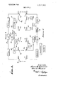
- FIG. 1 is a block diagram illustrating one form of the invention
- FIG. 2 is a block diagram illustrating another form of the in vention.
- FIG. 3 is a block diagram showing still another embodiment of the invention.
- a master station A and slave station B are separated bydistance L, as indicated which is to be accurately determined.
- Transmitting and receiving antennas T, and R are shown at station A, and transmitting and receiving antennas T, and R, are shown at station B.
- a source for an RF carrier signal f is indicated at 10, it being electrically connected with T, as via line 11, transmission (power amplifications) stage 12 and line 13, for delivering source f, to T,.
- Feedback f is also delevered to stage 12, as via line 14.
- Means is provided at the second station to convert f, received on R, to an RF carrier signal f, delivered at 15 for transmission on T,
- Such means may for example include crystal-controlled oscillator 16 generating a carrier radio frequency f, and a mixer stage 17 connected with the oscillator at 18 (to receiv f and with the antenna R, via line 19, receiver amplification stage 20 and line 21, to produce f, at 22.
- f may be equal to f -f and may then be passed to feeder line 15 via power amplification stage 23.
- means is provided at the first station to convert f, received on R, to the feedback RF carrier signal f on line l4, as referred to, and characterized in that loop transmission of carrier and sideband frequencies is established, with production of reverberations occurring at a rate which is a function of the L distance.
- Such means may for example include crystal controlled oscillator 25 generating a carrier radio frequency f, and a mixer stage 26 connected with the oscillator at 27 (to receive f,) and with the antenna R, via line 28, receiver amplification stage 29 and line 30, to produce feedback 1", on line 14.
- f may be equal to f;,f,
- the signal follows a closed circuit or loop, and if the amplification at the various stages referred to is sufficient, attenuation between stations will be overcome and feedback oscillation with reverberation will occur.
- the feedback oscillation will modulate the carriers, and sideband frequencies will be produced with values equal to the sum and difference of the carriers and feedback frequency. Assuming sideband frequency limits (away from the carrier) of 10 mc., a frequency variation of the feedback frequency from 0 to 10 me. may be accommodated or,
- Transit time of the signal between stations may be examined assuming 1 mile separation, total travel distance then being 2 miles. Taking the speed of electromagnetic waves at l86,000 m.p.s., the transmit time will be about 2/l86,000 or l0Xl0 seconds. An estimated accuracy in L measurement of one part in 125,000 thus becomes theoretically possible.
- the detection means may include a demodulator 35 having input connection 36 between R, and mixer 26, (and typically to line 30) to receive a small portion of the modulated carrier f with filtering and amplifications to detect the pulse rate of the generated sideband frequency, which pulse rate is an inversely proportional representation of the total distance L.
- the following derivations are illustrative:
- Equation l may be rewritten as follows:
- the distance L may be determined from equation (2) by substituting values as follows:
- Additional circuitry includes the oscillator 40 supplying the carrier frequency f for transmission by antenna T, at station A and reception by antenna R, at station B.
- the received signals is multiplied twice at 41 and supplied on line 42 as 2f It is amplified at 43 and retransmitted by antenna T for reception by antenna R station A.
- a multiplied version f ⁇ , off is supplied at 46 to the mixer 26 for conversion purposes, there being a multiplier 47 connecting lines 45 and 46 as shown.
- line 42 is connected with mixer via multiplier 48 and line 49, maintaining constant phase relationship as between f, on line 49 and f, on line 45. Representative values are:
- a delay control 50 for feedback f is connected between mixer 26 and amplifier stage l2.
- Additional circuitry includes oscillator 55 supplying carrier frequency f, for transmission by antenna T at station A and reception by antenna R at station B.
- the received signal is multiplied twice at 56, amplified at 57, and retransmitted at T for reception by antenna R, at station A.
- Another oscillator 60 supplies carrier signal f, for transmission by antenna T and reception by antenna R at station B.
- the received signal is amplified at 61 and delivered on line 62. Form the latter the signal is multiplied four times at 63 and supplied at J", to mixer 17.
- the f signal on line 62 is also delivered to multiplier 64 the output 2f of which is delivered to antenna T for transmission to antenna R at station A. From the latter the signal is delivered to multiplier 65, the 4f output of which is supplied as f, input to mixer 26.
- the 1",, input to the mixers have a constant phase delay relation. Representative values are:
- a delay control 70 for feedback f is connected between mixer 26 and amplifier stage 12.
- the combination comprising a. transmitting and receiving antennas T, and R, at the first station, and transmitting and receiving antennas T and R at the second station,
- means to convert f, received on R to an RF carrier signal f delivered for transmission on T means to convert f received in R, to a feedback RF carrier signal f, also delivered to T, and characterized in that loop transmission of carrier and sideband frequencies is established with production of reverberations occurring at a rate which is a function of said distance, and
- said converting means including mixers, and said source including an oscillator and at least one radio link means with antenna structure coupling said source and mixers.
- said detection means includes a demodulator having input connection between R, and the mixer at said first station to receive and demodulate the sideband frequency thereby producing a series of pulses, and a pulse rate counter connected to the demodulator output, the pulse rate being an inverse function of said distance.
- the combination comprising a. transmitting and receiving antennas T, and R, at the first station, and transmitting and receiving antennas T and R at the second station,
- said source for RF carrier f comprising an oscillator at the first station, and means including transmit and receive antennas to transmit the oscillator frequency output to the second station and back to the first station and to frequency multiplication means at at least one of said stations to produce said source f 5;
- the combination comprising a. transmitting and receiving antennas T and R at the first station, and transmitting and receiving antennas T and R at the second stat i o n,
- a source for an RF carrier signal f delivered for transmission on T c. means to convert f received on R, to an RF carrier signal f d elivere d for transmission on T (1. means to convert f; received on R to a feedback RF carrier signal f also delivered to T, and characterized in that loop transmission of carrier and sideband frequencies is established with production of reverberations occuring at a ra es h is a s laq s iiistaa l 2! v e. means responsive to said last-named means to detect said a rsxqr zsre i us f.
- said converting 6185a including an oscillator 567m of said stations to generate a frequency which is a submultiple of a frequency f a mixer connected to receive f and f and to produce said f, also delivered to T, and means coupling the oscillator output to the mixer to supply said f and including at least one radio link means with antenna structure between said stations and frequency multiplier me s.
- q y g l d i s is umsai lants ma structure at at least one of the stations.
Landscapes
- Engineering & Computer Science (AREA)
- Radar, Positioning & Navigation (AREA)
- Remote Sensing (AREA)
- Computer Networks & Wireless Communication (AREA)
- Physics & Mathematics (AREA)
- General Physics & Mathematics (AREA)
- Radar Systems Or Details Thereof (AREA)
Abstract
The disclosure concerns a ranging system based upon electromagnetic wave exchange between spaced stations to establish a closed loop circuit containing amplification stages, and wherein loop transmission of carrier and sideband frequencies is established with production of reverberations occurring at a rate which is a function of the distance between stations.
Description
United States Patent Inventors Joseph W. Crownover 6651 Avenida Mirola; John I. Wilhelm, 5962 Avenida Chamnez, both of, La J olla, Calif.
Appl, No. 818,870
Filed Apr. 24, 1969 Patented Oct. 5, 1971 ELECTRONIC DISTANCE FINDER 8 Claims, 3 Drawing Figs.
US. Cl. 343/6 R, 343/75, 343/12 Int. Cl G0ls 9/38 Field of Search 343/65, 6.5
LC, 7.5,12, 6 A, 6
[56] References Cited UNITED STATES PATENTS 2,779,018 1/1957 Gregoire et al. 343/12 2,837,736 6/1958 Golay 343/6 X 2,921,302 1/1960 Cartwright 34317.5 3,226,714 12/1965 Appelgarth, Jr 343/68 3,438,032 4/1969 Cook 343/65 X Primary Examiner-Malcolm F. Hubler Attorney-White & Haefliger ABSTRACT: The disclosure concerns a ranging system based upon electromagnetic wave exchange between spaced stations to establish a closed loop circuit containing amplification stages, and wherein loop transmission of carrier and sideband frequencies is established with production of reverberations occurring at a rate which is a function of the distance between stations.
carr/er- ELECTRONIC DISTANCE FINDER BACKGROUND OF THE INVENTION This invention relates generally to,ranging or distance finding, and more particularly concerns the use of reverberation frequency oscillation within a closed circuit established between spaced stations to determine distance between such stations.
Various electronic systems used in the past for ranging have included the echo principle (as for example radar), the radio wave phase-shift principle, and the optical laser beam transmissions. Such systems have certain disadvantages where lowcost'ranging devices are called for; for example, radar and laser systems are expensive and complex, and phase-shift procedures introduce ambiguities and require numerous readings on steadily diminishing lengths of wave refinement.
SUMMARY OF THE INVENTION It is a major object of the present invention to provide a simple, low-cost ranging system that will eliminate the disadvantages of prior systems, the invention being based upon the principle of electromagnetic wave exchange between stations to'establish a closed loop circuit containing amplification stages, and wherein loop transmission of carrier and sideband frequencies is established with production of reverberations occurring at a rate which is a function of the distance between such stations. It then becomes possible to detect the reverberation rate to arrive at an accurate determination of such distance.
Basically, the invention is embodied in a combination or '1 system that includes:
a. transmitting and receiving antennas T, and R, respectively at the first station, and transmitting and receiving antennas T, and R, respectively at the second station;
b. a source for an RF carrier signal f, delivered for transmission on T c. means at the second station to convert f, received on R, to an RF carrier signal f, delivered for transmission on T,
d. means at the first station to convert f, received on R, to a feedback RF carrier signal f, also delivered to T, and characterized in that loop or feedback transmission of carrier and sideband frequencies is established, with consequent production of reverberations occurring at a rate which is a function of the interstation distance; and
e. means connected to the system to detect the thus established reverberation rate.
Accordingly, the system can be considered as an amplifier with an active element feedback channel (the f, and f, transmission loop) connected between the output and input sides of the amplifier such that the channel extends over a distance to be measured, the transmission off, and f, over that channel being such that the source f carrier is modulated to produce sidebands, reverberations occurring at a rate which is a function of the distance to be measured. Regarding the active element" feedback loop, the converting means at the first station may typically include an oscillator generating a carrier frequency f, and a mixer connected to receive f, and f, and to produce the feedback f, delivered to T also, the converting means at the second station may typically include an oscillator generating a carrier frequency f}, and a mixer connected to receive f, and f, and to produce the f, delivered to T2. Further, the detection means may typically include a demodulator connected-between R, and the mixer at the first station to receive and demodulate the sideband frequency thereby producing a series of pulses (reverberations), and a pulse rate counter connected to the demodulator output, that rate being an inverse function of distance between the stations.
Another object of the invention is the provision of the same time delay for the primary source frequency f, and the heterodyning signal frequencies f, so as to produce constant phase relationship therebetween, for further accuracy. As will be seen, the source frequency f, and the signal frequency f, or
submultiples thereof, may be separately or conjointly transmitted over auxiliary radio links between the two stations, before introduction to the loop after appropriate multiplication.
These and other objects and advantages of the invention, as well as the details of illustrative embodiments, will be more fully understood from the following description and drawings, in which:
DRAWING DESCRIPTION FIG. 1 is a block diagram illustrating one form of the invention;
FIG. 2 is a block diagram illustrating another form of the in vention; and
FIG. 3 is a block diagram showing still another embodiment of the invention.
DESCRIPTION OF PREFERRED EMBODIMENTS Referring first to FIG. 1, a master station A and slave station B are separated bydistance L, as indicated which is to be accurately determined. Transmitting and receiving antennas T, and R, are shown at station A, and transmitting and receiving antennas T, and R, are shown at station B. A source for an RF carrier signal f, is indicated at 10, it being electrically connected with T, as via line 11, transmission (power amplifications) stage 12 and line 13, for delivering source f, to T,. Feedback f, is also delevered to stage 12, as via line 14.
Means is provided at the second station to convert f, received on R, to an RF carrier signal f, delivered at 15 for transmission on T, Such means may for example include crystal-controlled oscillator 16 generating a carrier radio frequency f, and a mixer stage 17 connected with the oscillator at 18 (to receiv f and with the antenna R, via line 19, receiver amplification stage 20 and line 21, to produce f, at 22. As an example, f, may be equal to f -f and may then be passed to feeder line 15 via power amplification stage 23.
Similarly, means is provided at the first station to convert f, received on R, to the feedback RF carrier signal f on line l4, as referred to, and characterized in that loop transmission of carrier and sideband frequencies is established, with production of reverberations occurring at a rate which is a function of the L distance. Such means may for example include crystal controlled oscillator 25 generating a carrier radio frequency f, and a mixer stage 26 connected with the oscillator at 27 (to receive f,) and with the antenna R, via line 28, receiver amplification stage 29 and line 30, to produce feedback 1", on line 14. As an example, f, may be equal to f;,f,
Thus, the signal follows a closed circuit or loop, and if the amplification at the various stages referred to is sufficient, attenuation between stations will be overcome and feedback oscillation with reverberation will occur. The feedback oscillation will modulate the carriers, and sideband frequencies will be produced with values equal to the sum and difference of the carriers and feedback frequency. Assuming sideband frequency limits (away from the carrier) of 10 mc., a frequency variation of the feedback frequency from 0 to 10 me. may be accommodated or,
Since the feedback frequency will depend upon the transmit time of signal around the entire system, an examination of the time loss of the signal passage through the electronic equipment is justified. Assuming f =l50 mc., the loss in elements 29, 26 and 12 will be on the order of 1/ I50 mc.=.0.0066 (10'6 sec. Assuming f, ==l00 mc., the loss in the elements 20, 17 and 23 will be on the order of II I00 mc.=0.0l (l0")sec.. whereby total time delay for the electronic equipment around the loop will be about 0.016 10"). In these cases f,=250 mc.
Transit time of the signal between stations may be examined assuming 1 mile separation, total travel distance then being 2 miles. Taking the speed of electromagnetic waves at l86,000 m.p.s., the transmit time will be about 2/l86,000 or l0Xl0 seconds. An estimated accuracy in L measurement of one part in 125,000 thus becomes theoretically possible.
The invention also embraces the provision of means to detect the reverberation rate. As shown in FIG. 1, the detection means may include a demodulator 35 having input connection 36 between R, and mixer 26, (and typically to line 30) to receive a small portion of the modulated carrier f with filtering and amplifications to detect the pulse rate of the generated sideband frequency, which pulse rate is an inversely proportional representation of the total distance L. In this regard, the following derivations are illustrative:
where f frequency in cycles per second of reverberation and equal to 1/D D =D +D delay time of entire system,
D; delay time within electronic equipment,
D delay time of waves between stations, and equal to L/C L distance between stations,
C velocity of electromagnetic waves.
Equation l may be rewritten as follows:
1 2L( D )C'. (2)
Assuming a detected reverberation frequency of 49,955 representing an unknown distance, and assuming D 0.016X as referred to above, the distance L may be determined from equation (2) by substituting values as follows:
2L=(0.0000200l8016-0.0000000l6) 109 2L=20,018.02l6=20,002.0 feet L=l0,00l.0 feet Any distance L less than about 50 feet will develop feedback frequency outside the :10 mc. limit of the sideband frequency. To maintain an accuracy of approximately one part in 30,000, the upper limits of the equipment are about 3 miles. At a distance of 5 miles, accuracy will diminish to about one part in 10,000. Therefore, the practical L range of the equipment may be considered to lie between the limits 50 feet and 5 miles.
Turning to FIG. 2, those elements remaining the same as in FIG. I bear the same numerals. Additional circuitry includes the oscillator 40 supplying the carrier frequency f for transmission by antenna T, at station A and reception by antenna R, at station B. The received signals is multiplied twice at 41 and supplied on line 42 as 2f It is amplified at 43 and retransmitted by antenna T for reception by antenna R station A. From R the signal 2f, is multiplied twice at 44 and supplied as the source signal f,=4f, A multiplied version f}, off, is supplied at 46 to the mixer 26 for conversion purposes, there being a multiplier 47 connecting lines 45 and 46 as shown. Thus, the phase delay relation between )3 3 and source f, remain the same. Similarly, line 42 is connected with mixer via multiplier 48 and line 49, maintaining constant phase relationship as between f, on line 49 and f, on line 45. Representative values are:
,=50 mc. f,=200 mc. f =600 mc. f =800 mc.
A delay control 50 for feedback f, is connected between mixer 26 and amplifier stage l2.
Turning to FIG. 3, the elements which are the same as in FIG. 1, again, bear the same numbers. Additional circuitry includes oscillator 55 supplying carrier frequency f, for transmission by antenna T at station A and reception by antenna R at station B. The received signal is multiplied twice at 56, amplified at 57, and retransmitted at T for reception by antenna R, at station A. The signal is multiplied twice at 58 and supplied as f,=4f,, to the stage 12.
Another oscillator 60 supplies carrier signal f, for transmission by antenna T and reception by antenna R at station B. The received signal is amplified at 61 and delivered on line 62. Form the latter the signal is multiplied four times at 63 and supplied at J", to mixer 17. The f signal on line 62 is also delivered to multiplier 64 the output 2f of which is delivered to antenna T for transmission to antenna R at station A. From the latter the signal is delivered to multiplier 65, the 4f output of which is supplied as f, input to mixer 26. Thus, the 1",, input to the mixers have a constant phase delay relation. Representative values are:
A delay control 70 for feedback f, is connected between mixer 26 and amplifier stage 12.
We claim:
1. In apparatus for determining with accuracy the distance between first and second stations which are spaced apart, the combination comprising a. transmitting and receiving antennas T, and R, at the first station, and transmitting and receiving antennas T and R at the second station,
a source for an RF carrier signal f, delivered for transmission on T,
means to convert f, received on R to an RF carrier signal f delivered for transmission on T means to convert f received in R, to a feedback RF carrier signal f, also delivered to T, and characterized in that loop transmission of carrier and sideband frequencies is established with production of reverberations occurring at a rate which is a function of said distance, and
. means responsive to said last named means to detect said reverberation rate,
. said converting means including mixers, and said source including an oscillator and at least one radio link means with antenna structure coupling said source and mixers.
2. The combination of claim 1 wherein said detection means includes a demodulator having input connection between R, and the mixer at said first station to receive and demodulate the sideband frequency thereby producing a series of pulses, and a pulse rate counter connected to the demodulator output, the pulse rate being an inverse function of said distance.
3. The combination of claim 1 wherein said stations are separated by a distance of between 50 feet and 5 miles.
4. In apparatus for determining with accuracy the distance between first and second stations which are spaced apart, the combination comprising a. transmitting and receiving antennas T, and R, at the first station, and transmitting and receiving antennas T and R at the second station,
b. a source for an RF carrier signal f, delivered for transmission on T,
0. means to convert f received on R, to an RF carrier signal f delivered for transmission on T d. means to convert f received on R, to a feedback RF carrier signal f, also delivered to T, and characterized in that loop transmission of carrier and sideband frequencies is established with production of reverberations occuring at a rate which is a function of said distance, and
e. means responsive to said last named means to detect said reverberation rate,
f. said source for RF carrier f, comprising an oscillator at the first station, and means including transmit and receive antennas to transmit the oscillator frequency output to the second station and back to the first station and to frequency multiplication means at at least one of said stations to produce said source f 5; In apparatus for determining with accuracy the distance between first and second stations which are spaced apart, the combination comprising a. transmitting and receiving antennas T and R at the first station, and transmitting and receiving antennas T and R at the second stat i o n,
b. a source for an RF carrier signal f delivered for transmission on T c. means to convert f received on R, to an RF carrier signal f d elivere d for transmission on T (1. means to convert f; received on R to a feedback RF carrier signal f also delivered to T, and characterized in that loop transmission of carrier and sideband frequencies is established with production of reverberations occuring at a ra es h is a s laq s iiistaa l 2! v e. means responsive to said last-named means to detect said a rsxqr zsre i us f. said converting 6185a; including an oscillator 567m of said stations to generate a frequency which is a submultiple of a frequency f a mixer connected to receive f and f and to produce said f, also delivered to T, and means coupling the oscillator output to the mixer to supply said f and including at least one radio link means with antenna structure between said stations and frequency multiplier me s. q y g l d i s is umsai lants ma structure at at least one of the stations.
6. The combination of claim 5 wherein the oscillator is at the first station, there being one radio link coupling the oscillator output from the first station to the second station and another radio link coupling one frequency multiplied version of the oscillator output from the second station back to the first station, said one frequency multiplied version being generated by said frequency multiplier means.
7. The combination of claim 6 wherein said means c to convert f, to f is coupled at the second station to said one frequency multiplied version of the oscillator output.
8. The combination of claim 7 wherein said means to convert f; to feedback f is coupled at the first station to another frequency multiplied version of the oscillator output derived from said one frequency multiplied version, said other frequency multiplied version being generated by said frequency multiplier means.
Claims (8)
1. In apparatus for determining with accuracy the distance between first and second stations which are spaced apart, the combination comprising a. transmitting and receiving antennas T1 and R1 at the first station, and transmitting and receiving antennas T2 and R2 at the second station, b. a source for an RF carrier signal f1 delivered for transmission on T1, c. means to convert f1 received on R2 to an RF carrier signal f2 delivered for transmission on T2, d. means to convert f2 received in R1 to a feedback RF carrier signal f1 also delivered to T1 and characterized in that loop transmission of carrier and sideband frequencies is established with production of reverberations occurring at a rate which is a function of said distance, and e. means responsive to said last named means to detect said reverberation rate, f. said converting means including mixers, and said source including an oscillator and at least one radio link means with antenna structure coupling said source and mixers.
2. The combination of claim 1 wherein said detection means includes a demodulator having input connection between R1 and the mixer at said first station to receive and demodulate the sideband frequency thereby producing a series of pulses, and a pulse rate counter connected to the demodulator output, the pulse rate being an inverse function of said distance.
3. The combination of claim 1 wherein said stations are separated by a distance of between 50 feet and 5 miles.
4. In apparatus for determining with accuracy the distance between first and second stations which are spaced apart, the combination comprising a. transmitting and receiving antennas T1 and R1 at the first station, and transmitting and receiving antennas T2 and R2 at the second station, b. a source for an RF carrier signal f1 delivered for transmission on T1, c. means to convert f 1 received on R2 to an RF carrier signal f2 delivered for transmission on T2, d. means to convert f2 received on R1 to a feedback RF carrier signal f1 also delivered to T1 and characterized in that loop transmission of carrier and sideband frequencies is established with production of reverberations occuring at a rate which is a function of said distance, and e. means responsive to said last named means to detect said reverberation rate, f. said source for RF carrier f1 comprising an oscillator at the first station, and means including transmit and receive antennas to transmit the oscillator frequency output to the second station and back to the first station and to frequency multiplication means at at least one of said stations to produce said source f1.
5. In apparatus for determining with accuracy the distance between first and second stations which are spaced apart, the combination comprising a. transmitting and receiving antennas T1 and R1 at the first station, and transmitting and receiving antennas T2 and R2 at the second station, b. a source for an RF carrier signal f1 delivered for transmission on T1, c. means to convert f1 received on R2 to an RF carrier signal f2 delivered for transmission on T2, d. means to convert f2 received on R1 to a feedback RF carrier signal f1 also delivered to T1 and characterized in that loop transmission of carrier and sideband frequencies is established with production of reverberations occuring at a rate which is a function of said distance, and e. means responsive to said last-named means to detect said reverberation rate, f. said converting means (d) including an oscillator at one of said stations to generate a frequency which is a submultiple of a frequency f3, a mixer connected to receive f3 and f2 and to produce said f1 also delivered to T1 and means coupling the oscillator output to the mixer to supply said f3 and including at least one radio link means with antenna structure between said stations and frequency multiplier means connected in series with said antenna structure at at least one of the stations.
6. The combination of claim 5 wherein the oscillator is at the first station, there being one radio link coupling the oscillator output from the first station to the second station and another radio link coupling one frequency multiplied version of the oscillator output from the second station back to the first station, said one frequency multiplied version being generated by said frequency multiplier means.
7. The combination of claim 6 wherein said meaNs c to convert f1 to f2 is coupled at the second station to said one frequency multiplied version of the oscillator output.
8. The combination of claim 7 wherein said means to convert f2 to feedback f1 is coupled at the first station to another frequency multiplied version of the oscillator output derived from said one frequency multiplied version, said other frequency multiplied version being generated by said frequency multiplier means.
Applications Claiming Priority (1)
| Application Number | Priority Date | Filing Date | Title |
|---|---|---|---|
| US81887069A | 1969-04-24 | 1969-04-24 |
Publications (1)
| Publication Number | Publication Date |
|---|---|
| US3611368A true US3611368A (en) | 1971-10-05 |
Family
ID=25226646
Family Applications (1)
| Application Number | Title | Priority Date | Filing Date |
|---|---|---|---|
| US818870A Expired - Lifetime US3611368A (en) | 1969-04-24 | 1969-04-24 | Electronic distance finder |
Country Status (1)
| Country | Link |
|---|---|
| US (1) | US3611368A (en) |
Cited By (3)
| Publication number | Priority date | Publication date | Assignee | Title |
|---|---|---|---|---|
| US3701151A (en) * | 1971-02-23 | 1972-10-24 | Toyota Motor Co Ltd | Method and apparatus for measuring the distance of travel and the speed of a moving object |
| US4307397A (en) * | 1977-12-05 | 1981-12-22 | The South African Inventions Development Corporation | Method of and apparatus for measuring distance |
| US5163004A (en) * | 1991-01-11 | 1992-11-10 | Cartesian Devices | Position tracking system |
Citations (5)
| Publication number | Priority date | Publication date | Assignee | Title |
|---|---|---|---|---|
| US2779018A (en) * | 1949-07-07 | 1957-01-22 | Onera (Off Nat Aerospatiale) | Electro-magnetic distance measuring device |
| US2837736A (en) * | 1955-02-08 | 1958-06-03 | Marcel J E Golay | Radio interferometry |
| US2921302A (en) * | 1956-08-09 | 1960-01-12 | Parsons Co Ralph M | Mode silencer for a closed loop transmission system |
| US3226714A (en) * | 1963-06-05 | 1965-12-28 | Nat Aeronautical Corp | Airborne distance measuring equipment |
| US3438032A (en) * | 1967-05-04 | 1969-04-08 | Holobeam | Apparatus for and method of measuring length |
-
1969
- 1969-04-24 US US818870A patent/US3611368A/en not_active Expired - Lifetime
Patent Citations (5)
| Publication number | Priority date | Publication date | Assignee | Title |
|---|---|---|---|---|
| US2779018A (en) * | 1949-07-07 | 1957-01-22 | Onera (Off Nat Aerospatiale) | Electro-magnetic distance measuring device |
| US2837736A (en) * | 1955-02-08 | 1958-06-03 | Marcel J E Golay | Radio interferometry |
| US2921302A (en) * | 1956-08-09 | 1960-01-12 | Parsons Co Ralph M | Mode silencer for a closed loop transmission system |
| US3226714A (en) * | 1963-06-05 | 1965-12-28 | Nat Aeronautical Corp | Airborne distance measuring equipment |
| US3438032A (en) * | 1967-05-04 | 1969-04-08 | Holobeam | Apparatus for and method of measuring length |
Cited By (3)
| Publication number | Priority date | Publication date | Assignee | Title |
|---|---|---|---|---|
| US3701151A (en) * | 1971-02-23 | 1972-10-24 | Toyota Motor Co Ltd | Method and apparatus for measuring the distance of travel and the speed of a moving object |
| US4307397A (en) * | 1977-12-05 | 1981-12-22 | The South African Inventions Development Corporation | Method of and apparatus for measuring distance |
| US5163004A (en) * | 1991-01-11 | 1992-11-10 | Cartesian Devices | Position tracking system |
Similar Documents
| Publication | Publication Date | Title |
|---|---|---|
| US3460139A (en) | Communication by radar beams | |
| US4851852A (en) | Decorrelation tolerant coherent radar altimeter | |
| US2424263A (en) | Radio system for distance and velocity measurement | |
| US3396393A (en) | Measurement of the distance between two points based on measuring the travelling time of electromagnetic waves | |
| US3713154A (en) | Radar | |
| US2424796A (en) | Superheterodyne radio altimeter or locator | |
| US3732567A (en) | Junction range finder | |
| US3197773A (en) | Frequency modulated continuous wave navigation radar | |
| US3611368A (en) | Electronic distance finder | |
| GB1017108A (en) | Improvements in or relating to radio navigation systems utilizing satellites | |
| US3648177A (en) | Transmitter for distance-measuring system | |
| US4959654A (en) | Digitally generated two carrier phase coded signal source | |
| US2658195A (en) | Moving target indicating radar system | |
| US4218656A (en) | Arrangement for the remote transmission of information for the remote guidance of vehicles which are subject to severe acceleration | |
| US2556109A (en) | Radio distance measuring and like system | |
| US3166747A (en) | Fm-am correlation radar system | |
| US2923000A (en) | Microwave system for velocity measurements | |
| US3325736A (en) | Doppler cancelation system | |
| US3204240A (en) | Passive communication system | |
| US3197769A (en) | Doppler measurement systems | |
| RU2789416C1 (en) | Method for synchronous reception and processing of a request signal in an autodyne transceiver of an atmospheric radiosonde system | |
| US2839749A (en) | Precision electronic navigation system | |
| JPS61124881A (en) | Synthetic aperture radar transmitter-receiver | |
| US3482247A (en) | Instrument landing system | |
| JPS6340891A (en) | Distance measuring instrument for artificial satellite tracking station |