US3599067A - Overload disconnect arrangement - Google Patents
Overload disconnect arrangement Download PDFInfo
- Publication number
- US3599067A US3599067A US12271A US3599067DA US3599067A US 3599067 A US3599067 A US 3599067A US 12271 A US12271 A US 12271A US 3599067D A US3599067D A US 3599067DA US 3599067 A US3599067 A US 3599067A
- Authority
- US
- United States
- Prior art keywords
- insulating ring
- members
- set forth
- combination set
- brush elements
- Prior art date
- Legal status (The legal status is an assumption and is not a legal conclusion. Google has not performed a legal analysis and makes no representation as to the accuracy of the status listed.)
- Expired - Lifetime
Links
- 239000011810 insulating material Substances 0.000 claims description 3
- 230000007246 mechanism Effects 0.000 description 9
- RYGMFSIKBFXOCR-UHFFFAOYSA-N Copper Chemical compound [Cu] RYGMFSIKBFXOCR-UHFFFAOYSA-N 0.000 description 3
- 229910052802 copper Inorganic materials 0.000 description 3
- 239000010949 copper Substances 0.000 description 3
- OKTJSMMVPCPJKN-UHFFFAOYSA-N Carbon Chemical compound [C] OKTJSMMVPCPJKN-UHFFFAOYSA-N 0.000 description 2
- 230000000712 assembly Effects 0.000 description 2
- 238000000429 assembly Methods 0.000 description 2
- 229910052799 carbon Inorganic materials 0.000 description 2
- 229920001875 Ebonite Polymers 0.000 description 1
- JOYRKODLDBILNP-UHFFFAOYSA-N Ethyl urethane Chemical compound CCOC(N)=O JOYRKODLDBILNP-UHFFFAOYSA-N 0.000 description 1
- 229910000760 Hardened steel Inorganic materials 0.000 description 1
- 230000015556 catabolic process Effects 0.000 description 1
- 239000004568 cement Substances 0.000 description 1
- 230000006835 compression Effects 0.000 description 1
- 238000007906 compression Methods 0.000 description 1
- 239000004020 conductor Substances 0.000 description 1
- 238000010276 construction Methods 0.000 description 1
- 230000008878 coupling Effects 0.000 description 1
- 238000010168 coupling process Methods 0.000 description 1
- 238000005859 coupling reaction Methods 0.000 description 1
- 239000000314 lubricant Substances 0.000 description 1
- 238000003754 machining Methods 0.000 description 1
- 239000002184 metal Substances 0.000 description 1
- 229910052751 metal Inorganic materials 0.000 description 1
- 238000000465 moulding Methods 0.000 description 1
- 230000002093 peripheral effect Effects 0.000 description 1
- 230000000717 retained effect Effects 0.000 description 1
- 125000006850 spacer group Chemical group 0.000 description 1
- 238000003466 welding Methods 0.000 description 1
Images


Classifications
-
- F—MECHANICAL ENGINEERING; LIGHTING; HEATING; WEAPONS; BLASTING
- F16—ENGINEERING ELEMENTS AND UNITS; GENERAL MEASURES FOR PRODUCING AND MAINTAINING EFFECTIVE FUNCTIONING OF MACHINES OR INSTALLATIONS; THERMAL INSULATION IN GENERAL
- F16D—COUPLINGS FOR TRANSMITTING ROTATION; CLUTCHES; BRAKES
- F16D43/00—Automatic clutches
- F16D43/02—Automatic clutches actuated entirely mechanically
- F16D43/20—Automatic clutches actuated entirely mechanically controlled by torque, e.g. overload-release clutches, slip-clutches with means by which torque varies the clutching pressure
- F16D43/202—Automatic clutches actuated entirely mechanically controlled by torque, e.g. overload-release clutches, slip-clutches with means by which torque varies the clutching pressure of the ratchet type
- F16D43/204—Automatic clutches actuated entirely mechanically controlled by torque, e.g. overload-release clutches, slip-clutches with means by which torque varies the clutching pressure of the ratchet type with intermediate balls or rollers
- F16D43/206—Automatic clutches actuated entirely mechanically controlled by torque, e.g. overload-release clutches, slip-clutches with means by which torque varies the clutching pressure of the ratchet type with intermediate balls or rollers moving axially between engagement and disengagement
-
- F—MECHANICAL ENGINEERING; LIGHTING; HEATING; WEAPONS; BLASTING
- F16—ENGINEERING ELEMENTS AND UNITS; GENERAL MEASURES FOR PRODUCING AND MAINTAINING EFFECTIVE FUNCTIONING OF MACHINES OR INSTALLATIONS; THERMAL INSULATION IN GENERAL
- F16D—COUPLINGS FOR TRANSMITTING ROTATION; CLUTCHES; BRAKES
- F16D2300/00—Special features for couplings or clutches
- F16D2300/20—Auxiliary indicators or alarms
Definitions
- ABSTRACT A safety overload disconnect arrangement between a pair of coaxial driving and driven rotary members which includes a plurality of axially spring-biased bearing balls mounted on one of the members and spaced circumferentially around the axis of rotation thereof. The balls engage in registering sockets on the other member to yieldably couple the members together for rotation in unison.
- the driving member is adapted to be rotated [52] US. Cl. 318/475, by e
- This invention relates to a safety overload disconnect arrangement for releasably coupled driving and driven members.
- a driving member and a driven member are releasably connected such that in the event of an unduly high load or resistance on the driven member the two members are automatically uncoupled to prevent damage to the mechanism and the control circuit is opened to stop the driving member.
- the present invention has for its primary object a safety overload disconnect arrangement of the above described type which is of economical construction and reliable in its operation.
- the invention contemplates a mechanical overload disconnect wherein the driving and driven members are releasably connected by a plurality of axially spring-biased bearing balls on one of the members engaging circular sockets in the other member in a manner such that the balls tend to rotate upon starting and reversing of the mechanism so as to prevent binding of the balls in the sockets and such that in response to a predetermined overload or resistance on the driven member the bearing balls are adapted to retract from the sockets and thus permit relative movement between the driven and driving members.
- the invention also contemplates a safety overload disconnect of the type described which includes an electrical disconnect arrangement in the electrical control circuit in the event of a mechanical overload, the electrical disconnect being of a type which does not involve the use of moving parts and is, therefore, not subject to failure.
- FIG. I is a fragmentary side elevational view of a mechanism employing the safety disconnect arrangement of this invention.
- FIG. 2 is an end view of the arrangement shown in FIG. 1 as viewed along the line ll-II in FIG. I.
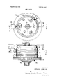
- FIG. 3 is a sectional view taken along the line III-III in FIG. 2.
- FIG. 4 is a sectional view along the line lV-lV in FIG. 3.
- FIG. 5 is a fragmentary sectional view along the line VV in FIG. 4.
- driver assembly I0 driven by a shaft 12 and a driven assembly 14 which includes a gear [6 for driving the mechanism to be operated.
- driver assembly It includes a sleeve I8 connected to shaft 12 by taper pins 20.
- Sleeve 18 has a radially outwardly extending flange 22 formed integrally therewith.
- a backplate 24 is secured to flange 22 by screws 26.
- the annular groove 28 between backplate 24 and flange 22 is of generally rectangular cross section and is filled by a ring 30 molded of a plastic insulating material, such as urethane, hard rubber, etc.
- Driven assembly 14 includes a hub 32 which is journaled on sleeve 18 by a bearing 34 and which is retained axially in place by a snap ring 36 and a needle bearing 38.
- Gear 16 is suitably mounted on hub 32 as by welding such as shown at 40.
- Hub 32 and flange 22 are formed with radial faces 42, 44, respectively, which are located in axially adjacent relation as shown in FIG. 3.
- Ring 30 has three bores 46 molded therein. At one end bores 46 register with sockets 48 in backplate 24 and at their opposite ends bores 46 register with bores 50 in flange 22.
- Sockets 48 are formed with a threaded opening 52 and hardened bushings 54 are press fitted in bores 50. Bores 50 are nonsymmetrically located with respect to the axis of shaft 12, (FIG. 3).
- Hub 32 is formed with three cylindrical sockets 56 which register axially with sockets $0 in flange 22.
- Hardened steel bushings 58 are press fitted in sockets 56. The inner diameter of bushings 58 is substantially smaller than the inner diameter of bushings 54.
- the driving and driven assemblies of the mechanism are releasably coupled by means of a bearing ball 60 disposed within each of the bushings 54 and urged axially into engagement with the chamfered seat 62 on bushings 58 by compression springs 64.
- Springs 64 are housed in the bores 46 molded in ring 30. At one end each spring 64 bears against a pressure pin 66 which in turn bears against the bearing balls 60 and at its opposite end each spring 64 bears against a pressure pin 68 which is backed up by a socket head screw 70 threaded in opening 52.
- the diameter of balls 60 is related in size to the diameter of the chamfered seat 62 of bushings 58 such that bushings 54 contact balls 60 in a plane extending through the center of balls 60 while the chamfered seats 62 contact the surface of balls 60 in a plane offset from the center of the balls.
- the pressure with which balls 60 are urged against seats 62 is adapted to be varied by adjusting screws 70.
- the tapered seats 62 urge balls 60 inwardly of bushings 54 against the tension of springs 64 and thus enables driver assembly 10 to rotate relative to driven assembly I4. Since the ball arrangement is not symmetrical relative to the axis of rotation, the driving connection between the two assemblies cannot be reestablished until the two members are relatively rotated to the single predetermined position wherein each ball 60 registers axially with its tapered seat 62 in bushings 58.
- the device of the present invention also provides an electrical disconnect.
- the electrical disconnect arrangement comprises a pair of carbon brushes 72, 74 which are mounted in a fixedly supported cartridge 76. Electrical conductors '78, are connected with brushes 72, 74 and extend to a low voltage control device such as a relay (not shown) for coupling with the electrical circuit such that when the circuit across brushes 74, 72 is opened, the electrical control circuit is also opened and the mechanism is deenergized.
- a pair of copper slip rings 82, 84 engaged by brushes 72, 74 are molded integrally with ring 30 around the periphery thereof.
- Slip rings 82, 84 are circumferentially continuous and may be machined from tubing. As shown in FIG. 3, slip rings 82, 84 are separated axially by an annular spacer lug 86 molded integrally with ring 30.
- the electrical disconnect arrangement includes a second pair of carbon brushes 88, 90 which project axially through the axially extending rim 9
- Brush 88 makes electrical contact with slip ring 82 through a spring 94 and brush 90 makes electrical contact with slip ring 84 through a spring 96 and a copper pin 98 which is brazed or otherwise electrically connected to slip ring 84.
- the portion of pin 98 extending axially through slip ring 82 is surrounded by an insulating sleeve I00.
- insulating ring 102 Around the outer peripheral portion of hub 32 there is molded an insulating ring 102 in which is embedded a copper contact plate 104.
- Plate 104 is located circumferentially on insulating ring 102 so that it forms bridging contact between brushes 88 and 90 when each of the bearing balls 60 is in seated engagement with its respective bearing seat 62 in bushings 58.
- the drive between driver asembly 10 and driven assembly 14 is uncoupled and the electrical control circuit is likewise opened by reason of the fact that contact plate 104 shifts circumferentially relative to brushes 88 and 90 so that it no longer makes bridging contact between these brushes.
- slip rings 82, 84 can be molded in place in ring 30 and the necessary bores and sockets in ring 30 can also be molded. This is particularly true with respect to the bores 46 for housing springs 64. It will be appreciated that the forming of bores 46 by molding them in ring 30 is considerably less expensive than machining these bores in metal. Furthermore, it is desirable to locate the balls 60 adjacent the outer periphery of the driving member as distinguished from adjacent its axis of rotation so that a larger driving force can be obtained with the same spring tension on springs 64.
- a rotary driving member a rotary driven member, means releasably connecting said members coaxially for rotation in unison such that when the load on the driven member is excessive the members are uncoupled and permitted to rotate relative to one another, means forming an electrical control circuit which when closed is adapted to supply electrical energy for controlling the rotation of the driving member, said circuit including a pair of circumferentially continuous slip rings on one of said members electrically insulated from one another, brush means contacting said slip rings and forming part of said circuit, said one member having a pair of brush elements thereon insulated from one another and electrically connected one with each of said slip rings, said other member having a contact plate thereon which when said members are in a predetermined coupled relation is adapted to bridge said brush elements to close said circuit, said contact plate being dimensioned such that when said members shift circumferentially out of said predetermined coupled relation said contact plate moves out of contact with at least one of said brush elements to thereby open said electrical circuit.
- a rotary driving member having a pair of radially extending faces which are axially juxtaposed, one of said members having a shaft portion extending coaxially from its radial face, the other member being journaled for rotation on said shaft portion, one of said members having a radially outwardly opening annular groove therein spaced axially from said radial face on said one member and defining a radially outwardly extending flange between one side of said groove and said last-mentioned radial face, a molded ring of insulating material filling said groove, said insulating ring having a plurality of circumferentially spaced, axially extending sockets therein extending to said flange, said flange having a plurality of through bores therein registering axially with said sockets, said radially extending face on said other member having a plurality of sockets therein registering axially with the bores on said flange
Landscapes
- Engineering & Computer Science (AREA)
- General Engineering & Computer Science (AREA)
- Mechanical Engineering (AREA)
- One-Way And Automatic Clutches, And Combinations Of Different Clutches (AREA)
- Transmission Devices (AREA)
- Motor Or Generator Current Collectors (AREA)
Applications Claiming Priority (1)
| Application Number | Priority Date | Filing Date | Title |
|---|---|---|---|
| US1227170A | 1970-02-18 | 1970-02-18 |
Publications (1)
| Publication Number | Publication Date |
|---|---|
| US3599067A true US3599067A (en) | 1971-08-10 |
Family
ID=21754166
Family Applications (1)
| Application Number | Title | Priority Date | Filing Date |
|---|---|---|---|
| US12271A Expired - Lifetime US3599067A (en) | 1970-02-18 | 1970-02-18 | Overload disconnect arrangement |
Country Status (5)
| Country | Link |
|---|---|
| US (1) | US3599067A (OSRAM) |
| JP (1) | JPS4836853B1 (OSRAM) |
| CA (1) | CA936817A (OSRAM) |
| FR (1) | FR2078731A5 (OSRAM) |
| GB (1) | GB1339064A (OSRAM) |
Cited By (10)
| Publication number | Priority date | Publication date | Assignee | Title |
|---|---|---|---|---|
| US3894698A (en) * | 1972-11-10 | 1975-07-15 | Morgaardshammar Ab | Jaw crusher |
| US4114078A (en) * | 1977-01-24 | 1978-09-12 | Malinski Richard F | Mechanical torque limit for valve actuator |
| US4257147A (en) * | 1979-04-17 | 1981-03-24 | White Consolidated Industries, Inc. | Overload clutch for the feed roll of a carding machine |
| US4273230A (en) * | 1978-11-24 | 1981-06-16 | Packaging Industries, Inc. | Indexing drive disconnect |
| US4569240A (en) * | 1984-03-05 | 1986-02-11 | Easom Engineering & Manufacturing Corp. | Motion generating mechanism |
| US4635769A (en) * | 1986-03-07 | 1987-01-13 | Canadian General Electric Company Limited | Gear protection system for grinding mills |
| US4678452A (en) * | 1985-07-26 | 1987-07-07 | Performance Feeders, Inc. | Overload release clutch |
| US4746320A (en) * | 1979-12-14 | 1988-05-24 | Unidynamics Corporation | Torque limiting clutch |
| US5896968A (en) * | 1997-04-22 | 1999-04-27 | The Carlson Company, Inc. | Torque limiting mechanism |
| US20100189570A1 (en) * | 2008-01-10 | 2010-07-29 | Hung-Chen Hsu | Intelligent auto-sensing pumping device |
Families Citing this family (8)
| Publication number | Priority date | Publication date | Assignee | Title |
|---|---|---|---|---|
| DE3004991A1 (de) * | 1980-02-11 | 1981-08-20 | Hilti AG, 9494 Schaan | Ueberlastkupplung zum uebertragen eines begrenzten drehmomentes |
| DE3236926C2 (de) * | 1982-10-06 | 1985-06-05 | Claudius Peters Ag, 2000 Hamburg | Mechanisch fremdschaltbare Drehkupplung |
| GB2158894A (en) * | 1984-05-15 | 1985-11-20 | Westinghouse Brake & Signal | Actuator comprising electric motor and torque limiting device |
| DE4300952A1 (de) * | 1993-01-15 | 1994-07-21 | Mayr Christian Gmbh & Co Kg | Überlastkupplung |
| US9573458B2 (en) * | 2012-10-03 | 2017-02-21 | Magna, International Inc. | Spring operated back-up/fail-safe module for active grille shutter systems |
| CN112360892B (zh) * | 2020-10-27 | 2022-04-26 | 嘉兴美茵钛传动科技有限公司 | 一种具有软启动功能的限矩联轴器 |
| CN112901669B (zh) * | 2021-03-22 | 2024-12-31 | 健亨科技(深圳)有限公司 | 一种无人装卸扭力离合器及防脱结构 |
| CN114195032B (zh) * | 2021-11-15 | 2023-03-24 | 法兰泰克重工股份有限公司 | 一种可变轨起升过载保护装置 |
Citations (3)
| Publication number | Priority date | Publication date | Assignee | Title |
|---|---|---|---|---|
| US2730666A (en) * | 1953-03-23 | 1956-01-10 | Jack H Cohen | Power control device for electric motor |
| US2757327A (en) * | 1953-03-09 | 1956-07-31 | Francis V Spronz | Motor control for door operation |
| US3252303A (en) * | 1962-08-06 | 1966-05-24 | Anthony V Weasler | Ball type torque limiting clutch |
-
1970
- 1970-02-18 US US12271A patent/US3599067A/en not_active Expired - Lifetime
- 1970-11-04 CA CA097381A patent/CA936817A/en not_active Expired
- 1970-12-28 JP JP45119484A patent/JPS4836853B1/ja active Pending
-
1971
- 1971-02-17 FR FR7105424A patent/FR2078731A5/fr not_active Expired
- 1971-04-19 GB GB2208171A patent/GB1339064A/en not_active Expired
Patent Citations (3)
| Publication number | Priority date | Publication date | Assignee | Title |
|---|---|---|---|---|
| US2757327A (en) * | 1953-03-09 | 1956-07-31 | Francis V Spronz | Motor control for door operation |
| US2730666A (en) * | 1953-03-23 | 1956-01-10 | Jack H Cohen | Power control device for electric motor |
| US3252303A (en) * | 1962-08-06 | 1966-05-24 | Anthony V Weasler | Ball type torque limiting clutch |
Cited By (10)
| Publication number | Priority date | Publication date | Assignee | Title |
|---|---|---|---|---|
| US3894698A (en) * | 1972-11-10 | 1975-07-15 | Morgaardshammar Ab | Jaw crusher |
| US4114078A (en) * | 1977-01-24 | 1978-09-12 | Malinski Richard F | Mechanical torque limit for valve actuator |
| US4273230A (en) * | 1978-11-24 | 1981-06-16 | Packaging Industries, Inc. | Indexing drive disconnect |
| US4257147A (en) * | 1979-04-17 | 1981-03-24 | White Consolidated Industries, Inc. | Overload clutch for the feed roll of a carding machine |
| US4746320A (en) * | 1979-12-14 | 1988-05-24 | Unidynamics Corporation | Torque limiting clutch |
| US4569240A (en) * | 1984-03-05 | 1986-02-11 | Easom Engineering & Manufacturing Corp. | Motion generating mechanism |
| US4678452A (en) * | 1985-07-26 | 1987-07-07 | Performance Feeders, Inc. | Overload release clutch |
| US4635769A (en) * | 1986-03-07 | 1987-01-13 | Canadian General Electric Company Limited | Gear protection system for grinding mills |
| US5896968A (en) * | 1997-04-22 | 1999-04-27 | The Carlson Company, Inc. | Torque limiting mechanism |
| US20100189570A1 (en) * | 2008-01-10 | 2010-07-29 | Hung-Chen Hsu | Intelligent auto-sensing pumping device |
Also Published As
| Publication number | Publication date |
|---|---|
| GB1339064A (en) | 1973-11-28 |
| DE2056962B2 (de) | 1973-01-04 |
| JPS4836853B1 (OSRAM) | 1973-11-07 |
| FR2078731A5 (OSRAM) | 1971-11-05 |
| CA936817A (en) | 1973-11-13 |
| DE2056962A1 (de) | 1971-08-26 |
Similar Documents
| Publication | Publication Date | Title |
|---|---|---|
| US3599067A (en) | Overload disconnect arrangement | |
| US4579201A (en) | Bidirectional, torque-limiting, no-back clutch mechanism | |
| US2668426A (en) | Torque limiting clutch | |
| US4685550A (en) | Quick disconnect mechanism | |
| US2660281A (en) | Slip clutch for screw actuators | |
| US3688522A (en) | Overload clutch permitting torque transmission during overload | |
| USRE26540E (en) | Bi-directional no-back drive device | |
| US4648498A (en) | Motor-operated clutch | |
| US1881728A (en) | Clutch device | |
| US3221118A (en) | Actuator with self-protecting limiting mechanism | |
| CN104723910A (zh) | 汽车座椅调高机构 | |
| US4293060A (en) | Electromagnetic friction clutch with overload release | |
| US4460078A (en) | Torque release clutch | |
| US3187862A (en) | Clutch mechanism with flexspline | |
| US2907432A (en) | Selective drive hub | |
| US3924421A (en) | Overload clutch | |
| CA1113280A (en) | Transmission assembly for powered and manual operation | |
| US4319672A (en) | Device for controlling the rotation of a driven rotary member | |
| US2300720A (en) | Cushion drive coupling | |
| US2720764A (en) | Flexible power transmission | |
| US3309942A (en) | Push-pull handwheel and motor drive | |
| US2082969A (en) | Clutch | |
| EP0627352A1 (en) | Electric power steering device | |
| US2037947A (en) | Universal joint | |
| US2219877A (en) | Clutch construction |