US3597112A - Compressor-blade-retaining means - Google Patents
Compressor-blade-retaining means Download PDFInfo
- Publication number
- US3597112A US3597112A US7579A US3597112DA US3597112A US 3597112 A US3597112 A US 3597112A US 7579 A US7579 A US 7579A US 3597112D A US3597112D A US 3597112DA US 3597112 A US3597112 A US 3597112A
- Authority
- US
- United States
- Prior art keywords
- recess
- groove
- blade
- loading slot
- adjacent
- Prior art date
- Legal status (The legal status is an assumption and is not a legal conclusion. Google has not performed a legal analysis and makes no representation as to the accuracy of the status listed.)
- Expired - Lifetime
Links
- 238000000034 method Methods 0.000 description 2
- 238000003825 pressing Methods 0.000 description 2
- 230000000717 retained effect Effects 0.000 description 2
- 230000014759 maintenance of location Effects 0.000 description 1
- 238000004519 manufacturing process Methods 0.000 description 1
- 239000007787 solid Substances 0.000 description 1
- 239000011800 void material Substances 0.000 description 1
Images
Classifications
-
- F—MECHANICAL ENGINEERING; LIGHTING; HEATING; WEAPONS; BLASTING
- F01—MACHINES OR ENGINES IN GENERAL; ENGINE PLANTS IN GENERAL; STEAM ENGINES
- F01D—NON-POSITIVE DISPLACEMENT MACHINES OR ENGINES, e.g. STEAM TURBINES
- F01D5/00—Blades; Blade-carrying members; Heating, heat-insulating, cooling or antivibration means on the blades or the members
- F01D5/30—Fixing blades to rotors; Blade roots ; Blade spacers
- F01D5/32—Locking, e.g. by final locking blades or keys
-
- F—MECHANICAL ENGINEERING; LIGHTING; HEATING; WEAPONS; BLASTING
- F01—MACHINES OR ENGINES IN GENERAL; ENGINE PLANTS IN GENERAL; STEAM ENGINES
- F01D—NON-POSITIVE DISPLACEMENT MACHINES OR ENGINES, e.g. STEAM TURBINES
- F01D5/00—Blades; Blade-carrying members; Heating, heat-insulating, cooling or antivibration means on the blades or the members
- F01D5/30—Fixing blades to rotors; Blade roots ; Blade spacers
- F01D5/3023—Fixing blades to rotors; Blade roots ; Blade spacers of radial insertion type, e.g. in individual recesses
- F01D5/303—Fixing blades to rotors; Blade roots ; Blade spacers of radial insertion type, e.g. in individual recesses in a circumferential slot
- F01D5/3038—Fixing blades to rotors; Blade roots ; Blade spacers of radial insertion type, e.g. in individual recesses in a circumferential slot the slot having inwardly directed abutment faces on both sides
Definitions
- the application describes means for retaining individual bladed members in their circumferential position on a gas turbine rotor spool.
- the invention comprises an elongated recess in the inner surface of a blade-root-retaining groove and a leaf spring disposed in the blind recess, which leaf spring includes a protuberance adapted to extend between the roots of two adjoining compressor blades.
- This invention relates to axial flow compressor rotor structure and more particularly to means for retaining the bladed members of such a structure in their position in a rotor spool.
- a common rotor structure used in axial flow compressors for gas turbine engines comprises a drum or spool having a surface which in part defines the airflow path through the compressor, and a plurality of airfoil bladed members secured to the spool in circumferential rows.
- the bladed members each include a root at the base of the airfoil, which root includes a necked-in portion.
- the roots are secured in circumferential grooves in the rotor spool, which grooves are adapted to secure the blade roots to restrain the blades from moving radially out of the rotor.
- Assembly of the blade roots into the blade-retaining grooves is ordinarily accomplished by inserting a blade root through a narrow loading slot cut into the groove at one or more discreet points along the circumference of the spool and then sliding the blades in the blade-retaining groove into their respective positions.
- the structure described, providing freedom for movement of the bladed members circumferentially of the spool also requires a locking device which will stop such movement in each row of bladed members after all the blades in a particular row have been assembled with the rotor spool.
- the locking device must be capable of withstanding the circumferential component of the airfoil aerodynamic load developed during compressor operation. At the same time, the locking device must be capable of permitting assembly and disassembly of the blade members to the spool with relative ease.
- a further object of the invention is to provide such a device which is relatively inexpensive to manufacture, which can be reused after disassembly, and which is not subject to constant elastic stress and the attendant possibility of relaxation of the elastically stressed member.
- the invention is a unique retaining means in combination with a turbomachine rotor assembly of the type comprising a circumferential blade-retaining groove having a loading slot formed therein and a plurality of blade members assembled therewith.
- the blade-retaining means comprises a leaf spring retainer disposed in an elongated recess located in the surface of the blade-retaining groove and in fixed dimensional relationship to the loading slot and includes a span maintained in spaced relation to the outwardly facing surface of the elongated recess spring.
- the leaf spring includes a protuberance located for alignment with the loading slot and extending into a space between two adjacent assembled blade roots.
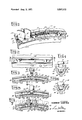
- FIG. 1 is a fragmented perspective view of a segment of a rotor spool having bladed members assembled therewith;
- FIG. 2 is a fragmented developed planned view of the rotor spool segment shown in FIG. 1;
- FIG. 3 is a fragmented section view taken along the line of 3-3 of FIG. 2;
- FIG. 4 is a fragmented section view taken along the line of 4-4 of FIG. 3;
- FIG. 5 is a fragmented section view taken along the line of 3-3 of FIG. 2 and additionally showing a compressor rotor blade as positioned during one step of the assembly of the blade to the rotor;
- FIG. 6 is a partially fragmented section view taken along the line 6-6 ofFIG. 5;
- FIG. 7 is a partially fragmented section view taken along the line 3-3 of FIG. 2 and additionally showing final assembly of the compressor rotor blades with the rotor spool and the blade-locking-means.
- the rotor assembly comprises a spool 10 (shown in segmented form) which includes a plurality of blade-retaining grooves 12, a plurality of bladed members 14 assembled to the spool 10 and retained by a groove 12, and a blade-retaining means 16 which is provided to maintain bladed members 14 in their circumferential positions on spool 10.
- Bladed members 14 each comprise an airfoil 18 extending radially from spool 10, a platform 20 located at the base of airfoil 18, and a root 22 in interlocking engagement with bladeretaining groove 12.
- root 22 comprises a relatively thin neck 24 adjacent the base 20 of bladed member 14, which neck is faired outwardly to an enlargement 26.
- Enlargement 26 is sized to fit snugly but slidably within the undercut 28 of blade-retaining groove 12, and neck 24 is similarly shaped and sized to fit snugly within the narrow portion 30 of blade-retaining groove 12.
- Spool 10 additionally includes a relief 32 on each side of blade-retaining groove 12 to accept platform 20 so that platform 20 will be flush with the spool outer surface 34 and in combination therewith form a smooth surface for the passage of air over the assembled compressor rotor.
- Retaining means 16 comprises an elongated recess 36, milled or otherwise formed in the bottom surface of bladeretaining groove 12 in alignment with the loading slot 38, and a spring retainer 40. As shown in FIG. 2, the elongated recess extends along the circumference of the inner surface of bladeretaining groove 12 and is centered with respect to loading slot 38.
- Spring retainer 40 is a leaf spring as shown comprising a leaf span 42 which can be slightly bowed outwardly in the unloaded state as shown and which includes a pad 44 at each of its ends to maintain leaf 42 in circumferential spaced relation and correct radial location with the bottom of recess 36 (see FIG. 3).
- a locking protuberance 46 extends outwardly from span 42 and becomes aligned upon assembly of spring 40 in recess 36 with loading slot 38. The protuberance on the leaf spring is just wide enough to space two adjacent blades correctly in the rotor with respect to the loading slot.
- stress relief grooves 48 are formed in the inner surface 50 of blade-retaining groove 12. Referring specifically to FIG. 2, these grooves are elongated blind slots milled or otherwise formed in surface 50 and located adjacent the ends of elongated recess 36. Each stress relief groove 48 has a depth adjacent recess 36 which is approximate that of recess 36 and extends circumferentially along surface 50 for a relatively short distance until it fairs into surface 50.
- FIGS. 37 Assembly of bladed members 14 with rotor spool 10 is illustrated by FIGS. 37.
- FIGS. 3 and 4 illustrate the first step of the assembly process wherein a bladed member 14 is positioned with its root 22 in alignment with loading slot 38.
- Spring retainer 40 is located in recess 36, its ends abutting the ends thereof and its span 42 maintained in spaced relation with the bottom thereof by pads 44.
- FIGS. 5 and 6 illustrate the second step of the assembly procedure wherein bladed member 14 is pushed inwardly against the elastic resisting force of spring retainer 40 to a position in which the contours of root 22 are aligned with the contours of blade-retaining groove 12. Once this alignment has been accomplished, bladed member 14 is then slid circumferentially in retaining groove 12 to a position in which the inner surface of root 22 has moved off the protuberance 46, as
- each bladed member 14 is loaded intoblade-retaining groove 12 as described above, it is moved along the circumference of the rotor spool 10 to make room for the next bladed member 14 until all but the final of the said bladed members are assembled to spool 10.
- the last of the said bladed members is inserted in the loading slot in the manner described above and then all the bladed members 14 are moved in the groove 12 until they assume the positions indicated in FIG. 7 by solid and broken line representations.
- protuberance 46 on spring retainer 40 is interposed between adjacent root members 22 and fills the void therebetween so that the entire row of bladed members 14 is held in its circumferential position in blade-retaining groove 12.
- spring retainer 40 After completion of assembly spring retainer 40 assumes its undeflected shape as shown in FIG. 3, thereby removing any continuous elastic stresses 42 and precluding the possibility of relaxation of span 42 which could render spring retainer 40 ineffective. It should, of course, be recognized that it may be desirable to slightly bias spring retainer 40 so that upon completion of the assembly described a small amount of elastic stress remains to assure a tight-fitting assembly.
- the bladed rotor assembly described herein can be readily disassembled by inserting a drift punch or similar tool through the hole 52 defined by adjacent blade platforms 20, pressing against protuberance 46 until it clears the inner surface of roots 22, and sliding bladed members 14 in groove 12 until a root 22 is aligned with loading slot 38, thereby permitting removal of a bladed member 14. Thereafter, successive bladed members can be removed through loading slot 38 by a pressing inwardly on spring retainer 40 to clear each successive blade root 22 and permit removal. After a sufficient number of bladed members 14 have been removed from blade-retaining groove 12, spring retainer 40 can be removed from the assembly and the remaining bladed members 14 readily removed through loading slot 38.
- the bladed rotor assembly described above possesses several advantages by virtue of its unique blade locking or retaining means, including ease of assembly and disassembly as described and minimization of elastic stresses in the assernbled spring retainer. Minimization of elastic stress in assembled spring retainer 40 is accomplished with no compromise in the functional integrity of the device inasmuch as during engine operation, rotation of the rotor spool 10 will give rise to centrifugal forces acting on spring retainer 40 which will maintain it in the position wherein protuberance 46 is positively engaged between adjacent roots 22 and pads 44 are circumferentially retained by the ends of retainin groove 36.
- blade-retaining means comprising,
- a spring retainer disposed in said recess, said retainer comprising a leaf spring whose ends are located in said recess in juxtaposition with the ends thereof, and whose intermediate span is in spaced relation to the blind surface of said recess, said retainer including a protuberance located for alignment with said loading slot and extending into the space between two adjacent blade roots.
- said leaf spring includes at each of its ends a pad which maintains the said spring in spaced relation with the blind surface of said recess.
- the inner surface of the blade-retaining groove additionally includes a pair of stress relief grooves adjacent opposite ends of said elongated recess, each said stress relief groove having approximately the same depth as said elongated recess at the end adjacent thereto and fairing into the said inner surface at a point removed from said recess.
- a turbomachine rotor assembly comprising,
- a rotor spool defining a flow path surface and including at least one retaining groove therein, said retaining groove extending circumferentially of said spool and including a relatively narrow portion adjacent the said flow surface and an undercut portion radially inward from said relatively narrow portion;
- each said bladed member comprising an airfoil and a root at the base of said airfoil, said root comprising a neck adjacent the base of said airfoil and an enlarged portion radially inward of and adjacent to said neck, said root being slidably engaged in said groove with said neck located in the relatively narrow portion of said groove and said enlarged portion located in the undercut portion of said groove;
- a spring retainer disposed in said elongated recess, said retainer comprising a leaf spring whose ends are located in said recess in juxtaposition with the ends thereof and whose span intermediate the ends is in spaced relation to the blind surface of said recess, said retainer further including a protuberance aligned with said loading slot, which protuberance extends into and circumferentially fills the space between two adjacent blade roots.
Landscapes
- Engineering & Computer Science (AREA)
- Mechanical Engineering (AREA)
- General Engineering & Computer Science (AREA)
- Turbine Rotor Nozzle Sealing (AREA)
- Structures Of Non-Positive Displacement Pumps (AREA)
Applications Claiming Priority (1)
| Application Number | Priority Date | Filing Date | Title |
|---|---|---|---|
| US757970A | 1970-02-02 | 1970-02-02 |
Publications (1)
| Publication Number | Publication Date |
|---|---|
| US3597112A true US3597112A (en) | 1971-08-03 |
Family
ID=21726999
Family Applications (1)
| Application Number | Title | Priority Date | Filing Date |
|---|---|---|---|
| US7579A Expired - Lifetime US3597112A (en) | 1970-02-02 | 1970-02-02 | Compressor-blade-retaining means |
Country Status (5)
| Country | Link |
|---|---|
| US (1) | US3597112A (en:Method) |
| BE (1) | BE762044A (en:Method) |
| DE (1) | DE2104511A1 (en:Method) |
| FR (1) | FR2078097A5 (en:Method) |
| GB (1) | GB1331711A (en:Method) |
Cited By (10)
| Publication number | Priority date | Publication date | Assignee | Title |
|---|---|---|---|---|
| US3902824A (en) * | 1974-07-29 | 1975-09-02 | Gen Motors Corp | Blade lock |
| US4255086A (en) * | 1979-06-27 | 1981-03-10 | Pratt & Whitney Aircraft Of Canada Limited | Locking device for blade mounting |
| US4462756A (en) * | 1981-12-30 | 1984-07-31 | Rolls Royce Limited | Rotor for fluid flow machine |
| US4818182A (en) * | 1987-06-10 | 1989-04-04 | Societe Nationale D'etude Et De Construction De Moteurs D-Aviation (Snecma) | System for locking turbine blades on a turbine wheel |
| GB2258273A (en) * | 1991-08-02 | 1993-02-03 | Ruston Gas Turbines Ltd | Rotor blade locking arrangement. |
| US20040013528A1 (en) * | 2002-07-20 | 2004-01-22 | Leathart Paul A. | Fan blade assembly |
| US20040062653A1 (en) * | 2002-09-27 | 2004-04-01 | Franco Di Paola | Blade retention scheme using a retention tab |
| US6739837B2 (en) | 2002-04-16 | 2004-05-25 | United Technologies Corporation | Bladed rotor with a tiered blade to hub interface |
| WO2005045200A1 (de) * | 2003-10-31 | 2005-05-19 | Mtu Aero Engines Gmbh | Turbomaschine und beschaufelter rotor für eine verdichterstufe einer turbomaschine |
| FR2997722A1 (fr) * | 2012-11-06 | 2014-05-09 | Snecma | Dispositif de blocage circonferentiel d'aubes marteau pour turbomachine, comprenant une piece d'actionnement de forme filaire |
Families Citing this family (3)
| Publication number | Priority date | Publication date | Assignee | Title |
|---|---|---|---|---|
| FR2758364B1 (fr) * | 1997-01-16 | 1999-02-12 | Snecma | Disque aubage a aubes tripodes |
| DE19963346A1 (de) * | 1999-12-27 | 2001-07-05 | Abb Alstom Power Ch Ag | Schaufelanordnung einer Strömungsmaschine und Verfahren zur Montage |
| FR3159192A1 (fr) * | 2024-02-08 | 2025-08-15 | Safran Aircraft Engines | Cale pour aube mobile de turbomachine |
Citations (4)
| Publication number | Priority date | Publication date | Assignee | Title |
|---|---|---|---|---|
| DE1085643B (de) * | 1959-04-13 | 1960-07-21 | Ehrhardt & Sehmer Ag Maschf | Laufschaufelbefestigung bei Axialstroemungsmaschinen |
| US3053504A (en) * | 1960-01-18 | 1962-09-11 | Rolls Royce | Method of assembling a bladed member |
| US3252687A (en) * | 1965-02-01 | 1966-05-24 | Gen Motors Corp | Rotor blade locking |
| US3383094A (en) * | 1967-01-19 | 1968-05-14 | Gen Electric | Rotor blade locking means |
-
1970
- 1970-02-02 US US7579A patent/US3597112A/en not_active Expired - Lifetime
-
1971
- 1971-01-26 BE BE762044A patent/BE762044A/xx unknown
- 1971-02-01 DE DE19712104511 patent/DE2104511A1/de active Pending
- 1971-02-02 FR FR7103478A patent/FR2078097A5/fr not_active Expired
- 1971-04-19 GB GB2075271A patent/GB1331711A/en not_active Expired
Patent Citations (4)
| Publication number | Priority date | Publication date | Assignee | Title |
|---|---|---|---|---|
| DE1085643B (de) * | 1959-04-13 | 1960-07-21 | Ehrhardt & Sehmer Ag Maschf | Laufschaufelbefestigung bei Axialstroemungsmaschinen |
| US3053504A (en) * | 1960-01-18 | 1962-09-11 | Rolls Royce | Method of assembling a bladed member |
| US3252687A (en) * | 1965-02-01 | 1966-05-24 | Gen Motors Corp | Rotor blade locking |
| US3383094A (en) * | 1967-01-19 | 1968-05-14 | Gen Electric | Rotor blade locking means |
Cited By (15)
| Publication number | Priority date | Publication date | Assignee | Title |
|---|---|---|---|---|
| US3902824A (en) * | 1974-07-29 | 1975-09-02 | Gen Motors Corp | Blade lock |
| US4255086A (en) * | 1979-06-27 | 1981-03-10 | Pratt & Whitney Aircraft Of Canada Limited | Locking device for blade mounting |
| US4462756A (en) * | 1981-12-30 | 1984-07-31 | Rolls Royce Limited | Rotor for fluid flow machine |
| US4818182A (en) * | 1987-06-10 | 1989-04-04 | Societe Nationale D'etude Et De Construction De Moteurs D-Aviation (Snecma) | System for locking turbine blades on a turbine wheel |
| GB2258273A (en) * | 1991-08-02 | 1993-02-03 | Ruston Gas Turbines Ltd | Rotor blade locking arrangement. |
| GB2258273B (en) * | 1991-08-02 | 1994-08-10 | Ruston Gas Turbines Ltd | Rotor blade locking arrangement |
| US6739837B2 (en) | 2002-04-16 | 2004-05-25 | United Technologies Corporation | Bladed rotor with a tiered blade to hub interface |
| US20040013528A1 (en) * | 2002-07-20 | 2004-01-22 | Leathart Paul A. | Fan blade assembly |
| US6905311B2 (en) * | 2002-07-20 | 2005-06-14 | Rolls-Royce Plc | Fan blade assembly |
| US20040062653A1 (en) * | 2002-09-27 | 2004-04-01 | Franco Di Paola | Blade retention scheme using a retention tab |
| US6837686B2 (en) * | 2002-09-27 | 2005-01-04 | Pratt & Whitney Canada Corp. | Blade retention scheme using a retention tab |
| WO2005045200A1 (de) * | 2003-10-31 | 2005-05-19 | Mtu Aero Engines Gmbh | Turbomaschine und beschaufelter rotor für eine verdichterstufe einer turbomaschine |
| US20070134100A1 (en) * | 2003-10-31 | 2007-06-14 | Mtu Aero Engines Gmbh | Turbine engine and bladed rotor for a compression stage of a turbine engine |
| US7399164B2 (en) | 2003-10-31 | 2008-07-15 | Mtu Aero Engines Gmbh | Turbine engine and bladed rotor for a compression stage of a turbine engine |
| FR2997722A1 (fr) * | 2012-11-06 | 2014-05-09 | Snecma | Dispositif de blocage circonferentiel d'aubes marteau pour turbomachine, comprenant une piece d'actionnement de forme filaire |
Also Published As
| Publication number | Publication date |
|---|---|
| DE2104511A1 (de) | 1971-08-12 |
| FR2078097A5 (en:Method) | 1971-11-05 |
| BE762044A (fr) | 1971-07-01 |
| GB1331711A (en) | 1973-09-26 |
Similar Documents
| Publication | Publication Date | Title |
|---|---|---|
| US3597112A (en) | Compressor-blade-retaining means | |
| US5242270A (en) | Platform motion restraints for freestanding turbine blades | |
| US3395891A (en) | Lock for turbomachinery blades | |
| US4915587A (en) | Apparatus for locking side entry blades into a rotor | |
| US5720596A (en) | Apparatus and method for locking blades into a rotor | |
| US4130379A (en) | Multiple side entry root for multiple blade group | |
| US3216699A (en) | Airfoil member assembly | |
| US3653781A (en) | Turbomachinery blade retainer | |
| US3689177A (en) | Blade constraining structure | |
| US4265595A (en) | Turbomachinery blade retaining assembly | |
| US4676723A (en) | Locking system for a turbine side entry blade | |
| US2786648A (en) | Blade locking device | |
| US3734646A (en) | Blade fastening means | |
| US3904317A (en) | Bucket locking mechanism | |
| US3216700A (en) | Rotor blade locking means | |
| US4767247A (en) | Apparatus and method for preventing relative blade motion in steam turbine | |
| US3598503A (en) | Blade lock | |
| KR102170572B1 (ko) | 터보기계 로터 조립체 및 방법 | |
| GB2097480A (en) | Rotor blade fixing in circumferential slot | |
| US3902824A (en) | Blade lock | |
| US4767273A (en) | Apparatus and method for reducing blade flop in steam turbine | |
| US3508844A (en) | Blade lock | |
| US3053504A (en) | Method of assembling a bladed member | |
| GB1187227A (en) | Improvements in Bladed Rotors for Axial Flow Compressors, Turbines and the like | |
| US2949278A (en) | Turbine blade retention |