US3568564A - Shotgun short stroke gas system - Google Patents
Shotgun short stroke gas system Download PDFInfo
- Publication number
- US3568564A US3568564A US763566A US3568564DA US3568564A US 3568564 A US3568564 A US 3568564A US 763566 A US763566 A US 763566A US 3568564D A US3568564D A US 3568564DA US 3568564 A US3568564 A US 3568564A
- Authority
- US
- United States
- Prior art keywords
- piston
- bolt assembly
- receiver
- gas
- piston means
- Prior art date
- Legal status (The legal status is an assumption and is not a legal conclusion. Google has not performed a legal analysis and makes no representation as to the accuracy of the status listed.)
- Expired - Lifetime
Links
- 239000007789 gas Substances 0.000 claims description 77
- 239000000567 combustion gas Substances 0.000 description 9
- 230000000712 assembly Effects 0.000 description 2
- 238000000429 assembly Methods 0.000 description 2
- 238000007789 sealing Methods 0.000 description 2
- 238000004140 cleaning Methods 0.000 description 1
- 238000010304 firing Methods 0.000 description 1
- 210000000245 forearm Anatomy 0.000 description 1
- 239000000463 material Substances 0.000 description 1
- 230000035515 penetration Effects 0.000 description 1
- 230000000737 periodic effect Effects 0.000 description 1
- 238000003466 welding Methods 0.000 description 1
Images

Classifications
-
- F—MECHANICAL ENGINEERING; LIGHTING; HEATING; WEAPONS; BLASTING
- F41—WEAPONS
- F41A—FUNCTIONAL FEATURES OR DETAILS COMMON TO BOTH SMALLARMS AND ORDNANCE, e.g. CANNONS; MOUNTINGS FOR SMALLARMS OR ORDNANCE
- F41A5/00—Mechanisms or systems operated by propellant charge energy for automatically opening the lock
- F41A5/18—Mechanisms or systems operated by propellant charge energy for automatically opening the lock gas-operated
Definitions
- ODay ABSTRACT A bolt-actuating gas system comprising an annular gas chamber, and annular piston, and an annular piston sleeve mounted on a tubular magazine wherein the piston, sleeve includes a push rod for contacting the bolt assembly.
- the push rod contacts the bolt assembly but is not connected thereto so that when the piston is moved through its work stroke, the push rod drives against the bolt assembly to propel the latter toward its retired position. Furthermore, the bolt as sembly can be manually retracted to its retired position Without causing concurrent movement of the piston, sleeve androd.
- This invention relates to a short stroke gas system for use in actuating the bolt assembly of a firearm, such as a shotgumor the like.
- a further disadvantage attendant to conventional gas operated shotguns lies in the exposure of the elements housed in the receiver to combustion gases when the gun is fired.
- the conventional gas operated shotgun in cludes at least one, and generally two slide arms which are connected to the bolt assembly and which are also generally connected to the gas'piston. Since the gas piston is positioned well forward on the gun, and the bolt assembly is rearward on the gun in the receiver, the slidearms-are of considerable length. The length of the conventional slide arms renders them flexible and subject tomeasurable bowing when the compressive force of the piston is applied to one end of the slide .arms when the gun is fired.
- sizeable apertures are cut through the front wall of the receiver. While the large apertures permit the slide arms to move freely through the front wall of the receiver, these apertures expose the various mechanical assemblies which are housed in the receiver to contaminated combustion gases which blow out of the gas cylinder toward the receiver. Exposure to these combustion gases causes undesirable deposits of material to form in the receiver, thus requiring periodic cleaning to remove these deposits.
- the gas system of this invention provides for a piston stroke which is shorter than the extent of movement of the bolt assembly during actuation of the latter.
- the gas system includes an annular bracket member mounted ,on the gun barrel and surrounding a portion of .a tubular cartridge magazine to define therewith an annular gas chamber.
- a ring-shaped piston member is slidably mounted on the magazine and disposed in the gas chamber, and a light weight piston sleeve member is connected to the piston and slidably mounted on the magazine to extend toward the receiver.
- a rigid push rod is connectedto the piston sleeve, the push rod extending rearward therefrom throughan aperture in the front wall of the receiver to a position adjacent the boltassembly.
- the rigidity of the rod permits the rod aperture to be only slightly larger than the outside diameter of the rod sothat a snug, sliding fit is achieved.
- the achievement of a snug fit between the rod and the aperture helps in greatly reducing ;the amount of combustion gas blow blown into the receiver.
- the bracket member includes lateral vents for exhausting combustion gases away from the receiver to further aid in reducing the amount of combustion gases blown into the receiver.
- a spring is mounted to bias the piston sleeve and piston toward the gas chamber.
- the push rod is not connected to the bolt assembly but is positioned next to the bolt assembly so that the rod is moved against the bolt assembly during the work stroke of the piston to begin movement of the bolt assembly toward its retired position after the gun is fired.
- the rod stops its rearward movement at the end of the work stroke of the piston, which occurs when the piston sleeve strikes the front face of the receiver, but the momentum imparted .to the bolt assembly from the rod causes the bolt assembly to move rearwardly to its retired position away from the rod.
- the automatic actuation of the bolt assembly is accomplished without the use of slide arms, or the like, connected to the bolt, and with minimum exposure of the interior of the receiver to combustion gases.
- the push rod is not connected to the bolt assembly, it is readily apparent that the bolt assembly can be manually retracted to its retired position without causing concurrent movement of the piston and piston sleeve.
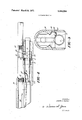
- FIG. 1 is an explodedside .view of the various components of a. preferred embodiment of the gas system of this invention
- FIG. 2 is a side elevation, partially in section, of a portion of a shotgunincluding the gas system of FIG. 1, with the bolt assembly of the gun and the various movable components of the gas system disposed in their. normal positions prior to firing the FIG. 3 is a vertical. sectional view taken along line 3-3 of FIG. 2; and
- FIG. 4 is a side elevation similar toFlG. 2, but showing the piston, piston sleeve, and push rod in their respectiverearwardmost positions with the bolt assembly immediately prior tomovement out of contact with the push rod.
- the system includes a conventional tubular magazine 2 which is mounted in any known manner beneath and parallel to the barrel of a shotgun.
- the forward end 4 of the magazine 2 is threaded to receive an end closure cap 6.
- An annular bracket member 8 is mounted on the magazine 2, the bracket 8 having a first bore 10 of a predetermined smaller diameter which is snugly fitted against the outside surface of the magazine 2 so as to form a gastight seal therewith.
- the bracket 8 also includes a second bore 12 of a predetermined layer diameter which is spaced apart from the outside surface of the magazine 2'to define therewith a gas chamber 52 (see FIG..2).
- a plurality of lateral gas vents 14 are disposed in the wall of the bracket 8 in communication with the second bore 12.
- a laterally directed gas bleed port 16 is drilled through the wall of the bracket 8 to communicate with the second bore 12 at a location adjacent to the first bore 10.
- An annular piston-member 18 having a first smaller bore 20 and a second larger bore 22 is slidably mounted on the magazine 2.
- An oblique face 24 is interposed between the bores 20 and 22, the face 24 preferably being formed at an angle of about 30 with the vertical.
- a pair of raised lands 26 are formed on the exterior of the piston 18 for gas sealing engagement with the larger bracket bore 12.
- a split ring 28 having an obliquely cut and face 30 and a normally cutface 32 is disposed within the piston bore 22, the face 30 being contiguous with the oblique piston face 24.
- a lightweight annular piston sleeve 34 is slidably mounted on the magazine 2 and extends into the piston bore 22 to snugly engage the piston 18.
- the inner end 36 of the sleeve 34 is adjacent to the normal face 32 of the ring 28.
- a rigid push rod 38 is affixed to the sleeve 34 as by welding, or the like, the rod 38 extending beyond the outer end of the sleeve 34.
- a compressible spring 40 is mounted on the rod 38, the spring bearing against the front wall of the receiver on one hand, and bearing against the end wall 42 of a slot 44 cut into the sleeve 34 on the other hand.
- FIG. 2 the gas system of FIG. 1 is shown mounted on a shotgun (only partially shown).
- the bracket 8 is mounted below the gun barrel 46, and a port 48 is drilled through the barrel 46 into the barrel bore 50.
- the port 48 is aligned with the gas bleed port 16 to provide a passage through which pressurized combustion gases are bled from the bore 50 into the gas chamber 52.
- bracket 8, piston 18, piston sleeve 34, and magazine 2 are all disposed within a forearm 54 mounted on on the barrel 46.
- the magazine 2 is connected in any conventional manner to the receiver 56 of the shotgun.
- the bolt slide 58 is shown in FIG. 2
- the bolt assembly in bolt assemblys the battery position.
- the remaining portions of the bolt assembly are omitted for purposes of clarity, it being understood that the bolt may take any conventional form. It isfurther understood that the bolt assembly is biased by a spring (not shown) toward the battery position in a conventional manner.
- the push rod 38 extends through an aperture 60 in the front wall 62 of the receiver 56.
- the size of the aperture 60 has been greatly exaggerated in FIG, 2 for purposes of clarity, however, itis to be understood that the diameter of the aperture 60 is preferably only about 0.003 in.'
- the left hand end of the rod 38 is contiguous with the front face of the bolt slide-58.
- the bolt slide 58 is mounted for reciprocal movement on a pair of rails 64 in the receiver 56.
- FIG. 3 shows the radial position of the various elements and the manner in which the push rod 38 contacts the'bolt slide 58.
- the bolt slide 58 is of sufficiently large mass to serve as an inertial body to continue rearward movement of the bolt assembly after the initial energy is supplied by the push rod 38.
- FIG. 4 shows the actuating positions of the various members of the gas system when a shot charge is fired from the gun.
- the shot charge 66 is shown as his propelled down the barrel bore at a position downstream of the aligned gas bleed ports 16 and 48.
- High-pressure combustion gases are bled through the ports 16 and 48 into' the gas chamber 52. These high pressure gases cause the piston 18 to move through the bracket bore 12 toward the receiver 56, thus driving the piston sleeve 34 and rod 38.
- the end point of the work stroke of the piston 18 is reached when the piston sleeve 34 strikes the front wall 62 of the receiver 56, this position being shown in FIG. 4.
- the spring 40 is compressed during the driving stroke of the piston 18. Movement of the piston 18 to the end point of its work stroke uncovers the gas vents 14 so as to vent the high pressure gases laterally out of the gas chamber 52 to lower the pressure therein.
- the split ring 28 flexes radially inwardly against the magazine 2, the tlexure resulting from the angular interface between the ring 28 and the piston face 24.
- the ring 28 thus provides a gastight seal between the piston 18 and the magazine 2, and also serves to scrape the magazine clean of any deposits during the work stroke of the piston.
- the resiliency of the ring 28 causes it to flex back to its normal loose fit about the magazine 2, thus offering no impedance to the returning of the piston to its original position.
- the mass of the bolt slide 58 is such that the bolt slide acts as an inertial body for the bolt assembly.
- the spring 40 acts to return the piston 18, piston sleeve 34 and rod 38 to their original position (shown in FIG. 2), even as the bolt assembly continues its rearward movement to is its retired position.
- the gas system of this invention permits a short piston stroke, while at the same time provides for proper automatic actuation of the the bolt assembly of the firearm. Furthermore, it is readily apparent that the bolt assembly in a gun incorporating the' gas system of this invention can be manually retracted .to its retired position without concurrent movement of the piston,
- a gas operated system for automatic reciprocation of said bolt assembly comprising:
- bracket means secured to said barrel and surrounding a portion of said magazine, said bracket means having a wall radially spaced from said magazine to provide therewith a gas chamber;
- port means interconnecting said gas chamber with a bore in said barrel
- annular piston means slidably mounted on said magazine and extending into said gas chamber, said piston means being movable through a relatively short work stroke and return;
- push means interposed between said piston means and said bolt assembly and extending through an aperture in said receiver, said push means being connected to said piston means and free of attachment with both said bolt assembly and said inertia means, said push means being operative to move against said bolt assembly and said inertia means to initiate reciprocation of 5 said bolt assembly when said piston means is driven through its work stroke, and to impart sufficient energy to said bolt assembly and said inertia means to cause the latter to continue reciprocation completely.
- said piston means comprises lightweight stop means operative to stop movement of said piston means by impact with said receiver after said piston means has been driven through its work stroke and before said piston means completely exits said gas chamber, whereby a portion of said piston means always remains in said gas chamber during said work stroke.
- bracket means comprises at least one laterally directed vent operative to lower gas pressure in said gas chamber after said piston means has been moved through its work stroke.
Landscapes
- Engineering & Computer Science (AREA)
- General Engineering & Computer Science (AREA)
- Pistons, Piston Rings, And Cylinders (AREA)
Applications Claiming Priority (1)
| Application Number | Priority Date | Filing Date | Title |
|---|---|---|---|
| US76356668A | 1968-09-30 | 1968-09-30 |
Publications (1)
| Publication Number | Publication Date |
|---|---|
| US3568564A true US3568564A (en) | 1971-03-09 |
Family
ID=25068184
Family Applications (1)
| Application Number | Title | Priority Date | Filing Date |
|---|---|---|---|
| US763566A Expired - Lifetime US3568564A (en) | 1968-09-30 | 1968-09-30 | Shotgun short stroke gas system |
Country Status (5)
| Country | Link |
|---|---|
| US (1) | US3568564A (enExample) |
| JP (1) | JPS495440B1 (enExample) |
| BE (1) | BE739596A (enExample) |
| DE (1) | DE1949361A1 (enExample) |
| FR (1) | FR2019253A1 (enExample) |
Cited By (22)
| Publication number | Priority date | Publication date | Assignee | Title |
|---|---|---|---|---|
| US4389920A (en) * | 1981-02-20 | 1983-06-28 | Dufour Sr Joseph H | Semiautomatic firearm |
| US5872323A (en) * | 1997-08-01 | 1999-02-16 | Remington Arms Co., Inc. | Gas operated firearm piston/piston seal assembly |
| US20050016374A1 (en) * | 2003-03-11 | 2005-01-27 | Giuseppe Pescini | Loading device for a semi-automatic rifle |
| US20050257681A1 (en) * | 2003-10-31 | 2005-11-24 | Keeney Michael D | Action rate control system |
| US20100024636A1 (en) * | 2008-07-29 | 2010-02-04 | Winge Michael L | Gas pressure mechanism in gas-operated firearm |
| US20100236396A1 (en) * | 2009-03-20 | 2010-09-23 | Stone Jeffrey W | Clamped gas block for barrel |
| US20100251885A1 (en) * | 2007-08-29 | 2010-10-07 | Stone Jeffrey W | Gas system for firearms |
| US20100282065A1 (en) * | 2007-08-29 | 2010-11-11 | Ra Brands, L.L.C. | Gas system for firearms |
| US8065949B1 (en) | 2006-05-24 | 2011-11-29 | Remington Arms Company, Inc. | Gas-operated firearm |
| US8176837B1 (en) | 2009-10-11 | 2012-05-15 | Jason Stewart Jackson | Firearm operating rod |
| US8640598B1 (en) | 2010-07-19 | 2014-02-04 | Jason Stewart Jackson | Sleeve piston for actuating a firearm bolt carrier |
| US8887616B2 (en) | 2013-01-11 | 2014-11-18 | Ra Brands, L.L.C. | Auto regulating gas system for supressed weapons |
| US8950313B2 (en) | 2013-01-04 | 2015-02-10 | Ra Brands, L.L.C. | Self regulating gas system for suppressed weapons |
| US9097475B2 (en) | 2012-12-05 | 2015-08-04 | Ra Brands, L.L.C. | Gas-operated firearm with pressure compensating gas piston |
| US20150226503A1 (en) * | 2012-08-06 | 2015-08-13 | Ata Silah San. A.S. | Novel operating system in the semi-automatic firearms |
| US9212856B2 (en) | 2012-12-26 | 2015-12-15 | Ra Brands, L.L.C. | Gas cut-off system for firearms |
| US9261314B1 (en) | 2010-07-19 | 2016-02-16 | Jason Stewart Jackson | Sleeve piston for actuating a firearm bolt carrier |
| US9347719B1 (en) | 2014-01-13 | 2016-05-24 | Ra Brands, L.L.C. | Replaceable feed ramp |
| US9383149B2 (en) | 2012-12-05 | 2016-07-05 | Ra Brands, L.L.C. | Gas-operated firearm with pressure compensating gas piston |
| US9383154B2 (en) | 2013-12-12 | 2016-07-05 | Ra Brands, L.L.C. | Gas vent for firearm |
| US9500423B2 (en) | 2014-01-24 | 2016-11-22 | Ra Brands, L.L.C. | Method and mechanism for automatic regulation of gas flow when mounting a suppressor to a firearm |
| US20250290715A1 (en) * | 2023-05-12 | 2025-09-18 | Zero Line, Inc. | Recoilless Gas Block System |
Families Citing this family (3)
| Publication number | Priority date | Publication date | Assignee | Title |
|---|---|---|---|---|
| IT1042954B (it) * | 1975-09-29 | 1980-01-30 | Eranchi Spa Luigi | Dispositivo azionato a gas per il comando dei mecchanismi di ricari ca di un fucile automatico a presa di gas |
| FR2603694B1 (fr) * | 1986-09-08 | 1990-08-10 | Exbrayat Cie | Fusil automatique a canon basculant ou non fonctionnant par emprunt de gaz |
| IT1311772B1 (it) * | 1999-12-10 | 2002-03-19 | Beretta Armi Spa | Fucile con presa gas perfezionato. |
Citations (5)
| Publication number | Priority date | Publication date | Assignee | Title |
|---|---|---|---|---|
| US2582989A (en) * | 1948-05-06 | 1952-01-22 | Earle M Harvey | Gas piston for firearms |
| US3200710A (en) * | 1963-12-27 | 1965-08-17 | Remington Arms Co Inc | Gas operating mechanism for autoloading firearm |
| US3246567A (en) * | 1964-06-15 | 1966-04-19 | Armalite Inc | Operating rod for self-loading firearm |
| US3386336A (en) * | 1966-03-30 | 1968-06-04 | Colt S Inc | Convertible machine gun for rightand left-hand cartridge feed and operation |
| US3420140A (en) * | 1966-03-25 | 1969-01-07 | Beretta Armi Spa | Mechanism for delaying release of bolt after firing a firearm |
-
1968
- 1968-09-30 US US763566A patent/US3568564A/en not_active Expired - Lifetime
-
1969
- 1969-09-29 JP JP44076968A patent/JPS495440B1/ja active Pending
- 1969-09-30 DE DE19691949361 patent/DE1949361A1/de active Pending
- 1969-09-30 FR FR6933414A patent/FR2019253A1/fr not_active Withdrawn
- 1969-09-30 BE BE739596D patent/BE739596A/xx unknown
Patent Citations (5)
| Publication number | Priority date | Publication date | Assignee | Title |
|---|---|---|---|---|
| US2582989A (en) * | 1948-05-06 | 1952-01-22 | Earle M Harvey | Gas piston for firearms |
| US3200710A (en) * | 1963-12-27 | 1965-08-17 | Remington Arms Co Inc | Gas operating mechanism for autoloading firearm |
| US3246567A (en) * | 1964-06-15 | 1966-04-19 | Armalite Inc | Operating rod for self-loading firearm |
| US3420140A (en) * | 1966-03-25 | 1969-01-07 | Beretta Armi Spa | Mechanism for delaying release of bolt after firing a firearm |
| US3386336A (en) * | 1966-03-30 | 1968-06-04 | Colt S Inc | Convertible machine gun for rightand left-hand cartridge feed and operation |
Cited By (34)
| Publication number | Priority date | Publication date | Assignee | Title |
|---|---|---|---|---|
| US4389920A (en) * | 1981-02-20 | 1983-06-28 | Dufour Sr Joseph H | Semiautomatic firearm |
| US5872323A (en) * | 1997-08-01 | 1999-02-16 | Remington Arms Co., Inc. | Gas operated firearm piston/piston seal assembly |
| US20050016374A1 (en) * | 2003-03-11 | 2005-01-27 | Giuseppe Pescini | Loading device for a semi-automatic rifle |
| US20050257681A1 (en) * | 2003-10-31 | 2005-11-24 | Keeney Michael D | Action rate control system |
| US7775149B2 (en) | 2003-10-31 | 2010-08-17 | Ra Brands, L.L.C. | Action rate control system |
| US8443712B2 (en) * | 2006-05-24 | 2013-05-21 | Ra Brands, L.L.C. | Gas-operated firearm |
| US20120017755A1 (en) * | 2006-05-24 | 2012-01-26 | Remington Arms Company, LLC | Gas-Operated Firearm |
| US8065949B1 (en) | 2006-05-24 | 2011-11-29 | Remington Arms Company, Inc. | Gas-operated firearm |
| US20100282065A1 (en) * | 2007-08-29 | 2010-11-11 | Ra Brands, L.L.C. | Gas system for firearms |
| US7946214B2 (en) | 2007-08-29 | 2011-05-24 | Ra Brands, L.L.C. | Gas system for firearms |
| US20100251885A1 (en) * | 2007-08-29 | 2010-10-07 | Stone Jeffrey W | Gas system for firearms |
| US8250964B2 (en) | 2007-08-29 | 2012-08-28 | Ra Brands, L.L.C. | Gas system for firearms |
| US8245625B2 (en) * | 2008-07-29 | 2012-08-21 | Winge Michael L | Gas pressure mechanism in gas-operated firearm |
| US20100024636A1 (en) * | 2008-07-29 | 2010-02-04 | Winge Michael L | Gas pressure mechanism in gas-operated firearm |
| US20100236396A1 (en) * | 2009-03-20 | 2010-09-23 | Stone Jeffrey W | Clamped gas block for barrel |
| US8109194B2 (en) | 2009-03-20 | 2012-02-07 | Ra Brands, L.L.C. | Clamped gas block for barrel |
| US8176837B1 (en) | 2009-10-11 | 2012-05-15 | Jason Stewart Jackson | Firearm operating rod |
| US8640598B1 (en) | 2010-07-19 | 2014-02-04 | Jason Stewart Jackson | Sleeve piston for actuating a firearm bolt carrier |
| US9261314B1 (en) | 2010-07-19 | 2016-02-16 | Jason Stewart Jackson | Sleeve piston for actuating a firearm bolt carrier |
| US20150226503A1 (en) * | 2012-08-06 | 2015-08-13 | Ata Silah San. A.S. | Novel operating system in the semi-automatic firearms |
| US9546833B2 (en) * | 2012-08-06 | 2017-01-17 | Ata Silah San. A.S. | Operating system in the semi-automatic firearms |
| US9383149B2 (en) | 2012-12-05 | 2016-07-05 | Ra Brands, L.L.C. | Gas-operated firearm with pressure compensating gas piston |
| US9097475B2 (en) | 2012-12-05 | 2015-08-04 | Ra Brands, L.L.C. | Gas-operated firearm with pressure compensating gas piston |
| US9816768B2 (en) | 2012-12-05 | 2017-11-14 | Ra Brands, L.L.C. | Gas-operated firearm with pressure compensating gas piston |
| US9212856B2 (en) | 2012-12-26 | 2015-12-15 | Ra Brands, L.L.C. | Gas cut-off system for firearms |
| US9328981B2 (en) | 2013-01-04 | 2016-05-03 | Ra Brands, L.L.C. | Self regulating gas system for suppressed weapons |
| US8950313B2 (en) | 2013-01-04 | 2015-02-10 | Ra Brands, L.L.C. | Self regulating gas system for suppressed weapons |
| US8887616B2 (en) | 2013-01-11 | 2014-11-18 | Ra Brands, L.L.C. | Auto regulating gas system for supressed weapons |
| US9383154B2 (en) | 2013-12-12 | 2016-07-05 | Ra Brands, L.L.C. | Gas vent for firearm |
| US9921019B2 (en) | 2013-12-12 | 2018-03-20 | Ra Brands, L.L.C. | Gas vent for firearm |
| US9347719B1 (en) | 2014-01-13 | 2016-05-24 | Ra Brands, L.L.C. | Replaceable feed ramp |
| US9562730B2 (en) | 2014-01-13 | 2017-02-07 | Ra Brands, L.L.C. | Replaceable feed ramp |
| US9500423B2 (en) | 2014-01-24 | 2016-11-22 | Ra Brands, L.L.C. | Method and mechanism for automatic regulation of gas flow when mounting a suppressor to a firearm |
| US20250290715A1 (en) * | 2023-05-12 | 2025-09-18 | Zero Line, Inc. | Recoilless Gas Block System |
Also Published As
| Publication number | Publication date |
|---|---|
| JPS495440B1 (enExample) | 1974-02-07 |
| FR2019253A1 (enExample) | 1970-06-26 |
| DE1949361A1 (de) | 1970-04-23 |
| BE739596A (enExample) | 1970-03-31 |
Similar Documents
| Publication | Publication Date | Title |
|---|---|---|
| US3568564A (en) | Shotgun short stroke gas system | |
| US3657960A (en) | Self aligning gas system for firearm | |
| US4389920A (en) | Semiautomatic firearm | |
| EP0266475A1 (en) | Gun with pivoting barrel and cocking mechanism | |
| US5257614A (en) | Gas powered gun | |
| US3246567A (en) | Operating rod for self-loading firearm | |
| US4028994A (en) | Micro-precision timed firing handgun | |
| CA1085249A (en) | Gas cartridge puncture device for gas fired guns | |
| US4231177A (en) | Automatic and semiautomatic small caliber conversion system | |
| US3580132A (en) | Buffer and delay mechanism for a firearm | |
| US4142314A (en) | Recoil assembly for a firearm adapter | |
| GB1424591A (en) | Tools employing propellant cartridges | |
| US2035539A (en) | Repeating firearm | |
| US2501069A (en) | Gas piston operated breechblock lock | |
| US3641692A (en) | Extractor and bolt mechanism for firearm firing caseless ammunition | |
| US2124172A (en) | Tear gas gun | |
| US3202055A (en) | Valve system for compression ignition device | |
| US3255942A (en) | Piston tool with fastener resetting arrangement | |
| US2922412A (en) | Cartridge cylinder for a toy gun | |
| US3122060A (en) | Cooperating firing and indexing devices for revolver-type firearms | |
| US2581395A (en) | Gas piston operated firearm | |
| US3235154A (en) | Piston tool | |
| US3410175A (en) | Recoil assembly for firearm | |
| US3233600A (en) | Gas charged repeater gun | |
| CN108139185B (zh) | 枪中的枪栓止动缓冲装置 |
Legal Events
| Date | Code | Title | Description |
|---|---|---|---|
| AS | Assignment |
Owner name: U.S. REPEATING ARMS COMPANY, 275 WINCHESTER AVE., Free format text: ASSIGNMENT OF ASSIGNORS INTEREST.;ASSIGNOR:OLIN CORPORATION, A CORP. OF VA;REEL/FRAME:004068/0574 Effective date: 19821026 |
|
| AS | Assignment |
Owner name: CREDIT LYONNAIS, NEW YORK BRANCH AND/OR CREDIT LYO Free format text: ASSIGNMENT OF ASSIGNORS INTEREST;ASSIGNOR:U.S. REPEATING ARMS COMPANY, INC.;REEL/FRAME:008382/0408 Effective date: 19961213 |
|
| AS | Assignment |
Owner name: U.S. REPEATING ARMS COMPANY, INC., CONNECTICUT Free format text: RELEASE AND TERMINATION OF COMPANY PATENT COLLATERAL ASSIGNMENT;ASSIGNORS:CREDIT LYONNAIS, NEW YORKBRANCH;CREDIT LYONNAIS CAYMAN ISLAND BRANCH;REEL/FRAME:008995/0631 Effective date: 19971231 |