US3565258A - Parallel flow hemodialyzer - Google Patents
Parallel flow hemodialyzer Download PDFInfo
- Publication number
- US3565258A US3565258A US830969A US3565258DA US3565258A US 3565258 A US3565258 A US 3565258A US 830969 A US830969 A US 830969A US 3565258D A US3565258D A US 3565258DA US 3565258 A US3565258 A US 3565258A
- Authority
- US
- United States
- Prior art keywords
- blood
- tubes
- dialysate
- tube
- cellophane
- Prior art date
- Legal status (The legal status is an assumption and is not a legal conclusion. Google has not performed a legal analysis and makes no representation as to the accuracy of the status listed.)
- Expired - Lifetime
Links
- 229920000298 Cellophane Polymers 0.000 claims abstract description 29
- 239000003822 epoxy resin Substances 0.000 claims abstract description 11
- 229920000647 polyepoxide Polymers 0.000 claims abstract description 11
- 239000008280 blood Substances 0.000 abstract description 71
- 210000004369 blood Anatomy 0.000 abstract description 70
- 230000017531 blood circulation Effects 0.000 abstract description 11
- 239000012528 membrane Substances 0.000 abstract description 6
- 239000004593 Epoxy Substances 0.000 abstract description 5
- 238000002474 experimental method Methods 0.000 description 12
- 238000001631 haemodialysis Methods 0.000 description 10
- 230000000322 hemodialysis Effects 0.000 description 10
- 239000012535 impurity Substances 0.000 description 9
- 239000011324 bead Substances 0.000 description 8
- DDRJAANPRJIHGJ-UHFFFAOYSA-N creatinine Chemical compound CN1CC(=O)NC1=N DDRJAANPRJIHGJ-UHFFFAOYSA-N 0.000 description 8
- 239000011780 sodium chloride Substances 0.000 description 7
- FAPWRFPIFSIZLT-UHFFFAOYSA-M Sodium chloride Chemical compound [Na+].[Cl-] FAPWRFPIFSIZLT-UHFFFAOYSA-M 0.000 description 5
- XSQUKJJJFZCRTK-UHFFFAOYSA-N Urea Chemical compound NC(N)=O XSQUKJJJFZCRTK-UHFFFAOYSA-N 0.000 description 5
- 239000004202 carbamide Substances 0.000 description 5
- 230000037452 priming Effects 0.000 description 5
- 229910003251 Na K Inorganic materials 0.000 description 4
- 229940109239 creatinine Drugs 0.000 description 4
- XLYOFNOQVPJJNP-UHFFFAOYSA-N water Substances O XLYOFNOQVPJJNP-UHFFFAOYSA-N 0.000 description 4
- 238000004519 manufacturing process Methods 0.000 description 2
- 150000003839 salts Chemical class 0.000 description 2
- 238000012360 testing method Methods 0.000 description 2
- 238000002560 therapeutic procedure Methods 0.000 description 2
- 241000282472 Canis lupus familiaris Species 0.000 description 1
- 208000007536 Thrombosis Diseases 0.000 description 1
- 230000015572 biosynthetic process Effects 0.000 description 1
- 230000036772 blood pressure Effects 0.000 description 1
- 208000020832 chronic kidney disease Diseases 0.000 description 1
- 208000022831 chronic renal failure syndrome Diseases 0.000 description 1
- 238000011109 contamination Methods 0.000 description 1
- 238000000502 dialysis Methods 0.000 description 1
- 230000003907 kidney function Effects 0.000 description 1
- 238000000034 method Methods 0.000 description 1
- 229920003023 plastic Polymers 0.000 description 1
- 239000004033 plastic Substances 0.000 description 1
- 239000002985 plastic film Substances 0.000 description 1
- 238000004382 potting Methods 0.000 description 1
- 125000002924 primary amino group Chemical group [H]N([H])* 0.000 description 1
- 238000013138 pruning Methods 0.000 description 1
- 238000000746 purification Methods 0.000 description 1
- 241000894007 species Species 0.000 description 1
Images

Classifications
-
- B—PERFORMING OPERATIONS; TRANSPORTING
- B01—PHYSICAL OR CHEMICAL PROCESSES OR APPARATUS IN GENERAL
- B01D—SEPARATION
- B01D61/00—Processes of separation using semi-permeable membranes, e.g. dialysis, osmosis or ultrafiltration; Apparatus, accessories or auxiliary operations specially adapted therefor
- B01D61/24—Dialysis ; Membrane extraction
- B01D61/28—Apparatus therefor
-
- B—PERFORMING OPERATIONS; TRANSPORTING
- B01—PHYSICAL OR CHEMICAL PROCESSES OR APPARATUS IN GENERAL
- B01D—SEPARATION
- B01D63/00—Apparatus in general for separation processes using semi-permeable membranes
- B01D63/06—Tubular membrane modules
- B01D63/069—Tubular membrane modules comprising a bundle of tubular membranes
-
- B—PERFORMING OPERATIONS; TRANSPORTING
- B01—PHYSICAL OR CHEMICAL PROCESSES OR APPARATUS IN GENERAL
- B01D—SEPARATION
- B01D2313/00—Details relating to membrane modules or apparatus
- B01D2313/04—Specific sealing means
- B01D2313/042—Adhesives or glues
Definitions
- This invention relates to an apparatus and method for extracorporeal hemodialysis and more particularly to hemodialysis with a small disposable unit usable in the home.
- Hemodialysis is a proven and life saving therapy for people with chronic renal failure. At the present time, hemodialysis is costly, time-consuming and complex. Hemodialysis for each patient usually costs from $10,000 to $25,000 per year and requires skilled medical and technicalpersonnel and also occupies valuable hospital bed space. It has been estimated that an annual increment of 50,000 people each year would benefit from hemodialysis therapy if it were economically and technically feasible, but at the present time,only about 900 persons are receiving treatment in the United States.
- a common type of machine used for hemodialysis consists of a tightly wound cellophane tube submerged in a dialysate. Blood containing various amino impurities such as urea and creatinine as well as excessive amounts of sodium chloride and other salts passes through the cellophane tube. Since the concentration of the various impurities in the blood is greater than the concentration of the impurities in the dialysate, a concentration gradient is established across the cellophane. The cellophane acts as a semipermeable membrane through which the impurities may pass but not the blood. Since the cel lophane tube is long and tightly 'wound, a blood pump is required to force blood through the tube.
- the blood in the tube is under greater pressure than the dialysate so a pressure gradient in addition to the aforementioned concentration gradient exists across the cellophane tube.
- the pressure gradient is a driving force which forces water from the blood into the dialysate.
- the blood is at greater pressure than the dialysate for two reasons: first, transfer of water from the blood is a renal function; and second, the greater pressure of the blood prevents contamination of the blood by dialysate if there is a leak in the tube.
- the machine has several disadvantages with respect to home use. Because the pressure drop from one end to the other of the cellophane tube is long, a blood pump is necessary to force blood through the tube. Blood clots may result from use of the pump and care must be taken to prevent their formation. In addition, the blood inventory in the cellophane tube is substantial and a transfusion often is required when the machine is used. Only part of this blood can be recovered from the machine and since blood is expensive, this represents a significant cost in hemodialysis. It is clear that the machinery necessary for hemodialysis is not only complicated and expensive, but the required transfusions and blood pump prevent its use by anyone other than trained medical personnel. All these factors in addition to the limited amount of available hospital space result in people dying every year because hemodialysis is not available to them.
- the dialyzer of this invention is related to that described in copending application Ser. No. 722,445.
- the applicants for both inventions are the same, and the inventions are related in that both concern dialyzers which make use of a plurality of short parallel semipermeable membrane tubes.
- the blood is under greater pressure than the dialysate in order to ensure that water transferas well as impurity transfer occurs.
- great care was required to prevent the blood from contacting sharp surfaces and to that end, considerable detail was devoted to providing rounded surfaces at the blood inlet. Steps included in providing rounded surfaces were the introduction of inserts into the cellophane tubes, two different potting steps and shims to reduce the volume of blood not in contact with the cellophane tubes.
- the present invention obviates the necessity for the intricate manufacturing steps required in the prior invention by reversing the flow paths of the dialysate and the blood so that the dialysate flows inside the tubes while blood flows across the tubes.
- the reversal of the dialysate and blood flow paths in the present invention gives rise to a significant simplification of the manufacturing procedures required for the device, as will be explained.
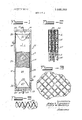
- FIG. 1 is a longitudinal section of a device according to the invention.
- FIG. 2 is a partial section taken along line 2-2 of FIG. 1.
- FIG. 3 is a partial section taken along line 3-3 of FIG. 2.
- FIGS. 4 and 5 are enlarged views of different embodiments of the invention.
- FIG. 6 is a section of a species of support members.
- dialyzer 10 is comprised of a rectangular housing 11 including parallel sides 12 and 13 and ends 14 and 15. Connected to housing 11 through end 15 is a dialysate inlet 16 and through end 14 a dialysate outlet 17. Also connected to the housing through side 13 is a blood inlet 18 and through side 12 is a blood outlet 19. A plurality of semipermeable membranes in the format elongated, flat cellophane tubes 20, each containing a nonwoven plastic mesh support 21, are disposed in parallel relationship within housing 11.
- Cellophane tubes 20 are slightly smaller than is housing 11 thereby providing room for a dialysate inlet manifold 22 with which dialysate inlet 16 communicates, a dialysate outlet manifold 23 with which dialysate outlet 17 communicates, a blood inlet manifold 24 with which blood inlet 18 communicates and a blood outlet manifold 25 with which blood outlet 19 communicates.
- a layer 26 of epoxy resin between the housing and the cellophane tubes on each side of the housing at the top and bottom thereof seal the inlet manifolds from the outlet manifolds and create a blood chamber between the dialysate inlet and outlet.
- each cellophane tube 20 has at each end and on each side of the tube, foldedback flaps 27 which have a tapered and rounded edge 28, the purpose of which will be later explained.
- Any epoxy resin head 29 seals each and every flap 27 to the flap of the next cellophane tube 20.
- the epoxy resin bead 29 is placed at a point on flap 27 to ensure a complete seal across the width of tubes 20.
- FIG. 3 shows in more detail the character of nonwoven mesh support 21 which is preferably as thin as possible.
- the mesh support 21 must be nonwoven in order to provide paths for blood flow resulting from deformation of the cellophane tubes 20 into the interstices of the mesh due to the pressure gradient between the blood and dialysate.
- FIG. 6 shows an alternate form of mesh support 2!.
- the support consists of a thin plastic sheet formed into alternately inverted hollow pyramids or cones 31 arranged so that an upward pointing pyramid 32 is surrounded on four sides by downward pointing pyramids 33.
- These support members are also described in the aforementioned related application.
- blood enters blood inlet 18 and flows into blood inlet manifold 24.
- the blood flows across cellophane tubes 20 into blood outlet manifold 25 and thereafter out of dialyzer 10 through blood outlet 19.
- the dialysate enters dialysate inlet 16 and flows from dialysate inlet manifold 22 through cellophane tubes 20 to dialysate outlet manifold 23 and out of the dialyzer 10 through dialysate outlet 17.
- flaps 27 will not be needed if the alternate support member 30 is used since pyramids 31 are so creatinine, sodium chloride and other salts.
- the blood flow rate and the dialysate flow rate were recorded in milliliter per minute. Blood samples were taken, analyzed and the dialysance of various impurities calculated. Di-
- alysance in milliliter per minute is defined as A-V m) X blOOd fiOW rate where: w A concentration of impurity in blood entering dialyzer;
- a hemodlalyzer comprising a housing having at one end a :22 gig g ⁇ 42 53 dialysate inlet leading to a dialysate inlet manifold and at the 456 336 58 2% 2 2% other end a dialysate outlet leading from a dialysate outlet :22 gag g 42 62 48 manifold; a blood chamber having a blood inlet manifold and 04 34 37 a blood outlet manifold between said dialysate inlet and outggi g 5 64 49 let, said blood chamber being sealed from said dialysate inlet 2; 360 46 if; g; g; manifold and outlet manifold; a plurality of semipermeable $3 3 41 63 71 membranes in the form of parallel tubes extending through the 24 696 44 41 69 7 blood chamber and sealingly connecting the dialysate inlet
- the embodiments of the invention in which an exclusive BF (:1) 1 5) Dmlysance (mL/mm) property or privilege is claimed are defined as follows: n-) l-l ea n Na K 2.
- the dialyzer of claim 1 wherein the tubes are cellophane 138 966 35 6 65 and have a wall thickness of about 1 mil.
Landscapes
- Chemical & Material Sciences (AREA)
- Chemical Kinetics & Catalysis (AREA)
- Health & Medical Sciences (AREA)
- Urology & Nephrology (AREA)
- Engineering & Computer Science (AREA)
- Water Supply & Treatment (AREA)
- External Artificial Organs (AREA)
- Separation Using Semi-Permeable Membranes (AREA)
Applications Claiming Priority (1)
| Application Number | Priority Date | Filing Date | Title |
|---|---|---|---|
| US83096969A | 1969-06-06 | 1969-06-06 |
Publications (1)
| Publication Number | Publication Date |
|---|---|
| US3565258A true US3565258A (en) | 1971-02-23 |
Family
ID=25258024
Family Applications (1)
| Application Number | Title | Priority Date | Filing Date |
|---|---|---|---|
| US830969A Expired - Lifetime US3565258A (en) | 1969-06-06 | 1969-06-06 | Parallel flow hemodialyzer |
Country Status (8)
| Country | Link |
|---|---|
| US (1) | US3565258A (da) |
| JP (1) | JPS495998B1 (da) |
| BE (1) | BE750656A (da) |
| CH (1) | CH511622A (da) |
| DK (1) | DK124013B (da) |
| FR (1) | FR2049163B1 (da) |
| GB (1) | GB1282338A (da) |
| SE (1) | SE361600B (da) |
Cited By (13)
| Publication number | Priority date | Publication date | Assignee | Title |
|---|---|---|---|---|
| FR2171043A1 (da) * | 1972-02-03 | 1973-09-21 | Atomic Energy Commission | |
| US3912637A (en) * | 1971-06-04 | 1975-10-14 | William G Esmond | Exchange device |
| US3956449A (en) * | 1975-03-18 | 1976-05-11 | Melvin Wexler | Flat plate dialyzer and method of making same |
| US4019988A (en) * | 1975-08-28 | 1977-04-26 | Extracorporeal Medical Specialities Inc. | Dialyzer membrane seal and tubing connector |
| US4022692A (en) * | 1975-08-01 | 1977-05-10 | Erika, Inc. | Non-woven support screen for mass transfer devices |
| DE2714754A1 (de) * | 1976-04-02 | 1977-11-03 | Medical Inc | Haemodialysator |
| US4261830A (en) * | 1978-11-04 | 1981-04-14 | Dr. Eduard Fresenius Chemisch-Pharmazeutische Industrie Kg Apparatebau Kg | Dialyzer |
| US4556489A (en) * | 1983-03-09 | 1985-12-03 | Shiley Incorporated | Membrane oxygenator |
| US4761229A (en) * | 1987-06-22 | 1988-08-02 | Thompson John A | Multi-leaf membrane module |
| US4824566A (en) * | 1985-06-24 | 1989-04-25 | The Dow Chemical Company | Assembly comprising a foraminous core, resinous tubesheet and self-locking, helically wound, hollow fiber bundle |
| US5104532A (en) * | 1989-09-15 | 1992-04-14 | Exxon Research And Engineering Company | Flat stack permeator |
| US20080227190A1 (en) * | 2007-03-14 | 2008-09-18 | Gambro Bct, Inc. | Cell Expansion Apparatus with Plate Bioreactor |
| GR1010930B (el) * | 2024-05-16 | 2025-04-29 | Εθνικο Κεντρο Ερευνας Και Τεχνολογικης Αναπτυξης (Ε.Κ.Ε.Τ.Α.), | Αποστατες συστηματων μεμβρανων με ανοικτου πλεγματος τρισδιαστατη γεωμετρια χωροδικτυωματων |
Citations (3)
| Publication number | Priority date | Publication date | Assignee | Title |
|---|---|---|---|---|
| US2664395A (en) * | 1949-08-24 | 1953-12-29 | Marchand John Felix | Dialyzer |
| US3228877A (en) * | 1960-09-19 | 1966-01-11 | Dow Chemical Co | Permeability separatory apparatus and process utilizing hollow fibers |
| US3362540A (en) * | 1966-08-24 | 1968-01-09 | Research Corp | Disc-shaped, multiple cone type dialyzer having a tapered flow path |
-
1969
- 1969-06-06 US US830969A patent/US3565258A/en not_active Expired - Lifetime
-
1970
- 1970-04-01 GB GB05350/70A patent/GB1282338A/en not_active Expired
- 1970-05-19 SE SE06807/70A patent/SE361600B/xx unknown
- 1970-05-20 BE BE750656D patent/BE750656A/xx not_active IP Right Cessation
- 1970-06-03 CH CH833570A patent/CH511622A/de not_active IP Right Cessation
- 1970-06-03 FR FR707020407A patent/FR2049163B1/fr not_active Expired
- 1970-06-04 DK DK290370AA patent/DK124013B/da not_active IP Right Cessation
- 1970-06-06 JP JP45048440A patent/JPS495998B1/ja active Pending
Patent Citations (3)
| Publication number | Priority date | Publication date | Assignee | Title |
|---|---|---|---|---|
| US2664395A (en) * | 1949-08-24 | 1953-12-29 | Marchand John Felix | Dialyzer |
| US3228877A (en) * | 1960-09-19 | 1966-01-11 | Dow Chemical Co | Permeability separatory apparatus and process utilizing hollow fibers |
| US3362540A (en) * | 1966-08-24 | 1968-01-09 | Research Corp | Disc-shaped, multiple cone type dialyzer having a tapered flow path |
Non-Patent Citations (1)
| Title |
|---|
| Kolff, W. J. Dialysis Becomes Practical, a publication of C. H. Boehringer Sohn, Ingelheim Am Rhein, pp. 4, 19, 27, 34, 36 and 37 relied on. * |
Cited By (13)
| Publication number | Priority date | Publication date | Assignee | Title |
|---|---|---|---|---|
| US3912637A (en) * | 1971-06-04 | 1975-10-14 | William G Esmond | Exchange device |
| FR2171043A1 (da) * | 1972-02-03 | 1973-09-21 | Atomic Energy Commission | |
| US3956449A (en) * | 1975-03-18 | 1976-05-11 | Melvin Wexler | Flat plate dialyzer and method of making same |
| US4022692A (en) * | 1975-08-01 | 1977-05-10 | Erika, Inc. | Non-woven support screen for mass transfer devices |
| US4019988A (en) * | 1975-08-28 | 1977-04-26 | Extracorporeal Medical Specialities Inc. | Dialyzer membrane seal and tubing connector |
| DE2714754A1 (de) * | 1976-04-02 | 1977-11-03 | Medical Inc | Haemodialysator |
| US4261830A (en) * | 1978-11-04 | 1981-04-14 | Dr. Eduard Fresenius Chemisch-Pharmazeutische Industrie Kg Apparatebau Kg | Dialyzer |
| US4556489A (en) * | 1983-03-09 | 1985-12-03 | Shiley Incorporated | Membrane oxygenator |
| US4824566A (en) * | 1985-06-24 | 1989-04-25 | The Dow Chemical Company | Assembly comprising a foraminous core, resinous tubesheet and self-locking, helically wound, hollow fiber bundle |
| US4761229A (en) * | 1987-06-22 | 1988-08-02 | Thompson John A | Multi-leaf membrane module |
| US5104532A (en) * | 1989-09-15 | 1992-04-14 | Exxon Research And Engineering Company | Flat stack permeator |
| US20080227190A1 (en) * | 2007-03-14 | 2008-09-18 | Gambro Bct, Inc. | Cell Expansion Apparatus with Plate Bioreactor |
| GR1010930B (el) * | 2024-05-16 | 2025-04-29 | Εθνικο Κεντρο Ερευνας Και Τεχνολογικης Αναπτυξης (Ε.Κ.Ε.Τ.Α.), | Αποστατες συστηματων μεμβρανων με ανοικτου πλεγματος τρισδιαστατη γεωμετρια χωροδικτυωματων |
Also Published As
| Publication number | Publication date |
|---|---|
| DK124013B (da) | 1972-09-04 |
| CH511622A (de) | 1971-08-31 |
| DE2024635A1 (de) | 1970-12-10 |
| DE2024635B2 (de) | 1976-09-30 |
| BE750656A (fr) | 1970-11-03 |
| FR2049163A1 (da) | 1971-03-26 |
| JPS495998B1 (da) | 1974-02-12 |
| FR2049163B1 (da) | 1973-02-02 |
| GB1282338A (en) | 1972-07-19 |
| SE361600B (da) | 1973-11-12 |
Similar Documents
| Publication | Publication Date | Title |
|---|---|---|
| US3746175A (en) | Compact dialyzer | |
| US3565258A (en) | Parallel flow hemodialyzer | |
| US3522885A (en) | Parallel flow hemodialyzer | |
| US3370710A (en) | Compact blood dialyzer with a pleated membrane therein | |
| US4033878A (en) | Spiral wound membrane module for direct osmosis separations | |
| EP0215849B1 (en) | Platelet collection system | |
| US4861485A (en) | Hemodiafiltration device | |
| US4540492A (en) | Method and apparatus for treating whole blood | |
| SU553912A3 (ru) | Искусственна почка | |
| US4125468A (en) | Hollow-fiber permeability apparatus | |
| US3788482A (en) | Folded membrane dialyzer | |
| KR20070083967A (ko) | Mecs 투석기 | |
| US4219422A (en) | Apparatus for mass transfer between fluids, provided with an interposed selectively permeable diaphragm unit | |
| US6852231B2 (en) | Spin-hemodialysis assembly and method | |
| US4282099A (en) | Integral partitioned hemodialysis unit | |
| GB1189458A (en) | Improvements in or relating to dialysers | |
| JPH11501866A (ja) | 濾過カセットとこれを積層したフィルタ | |
| JP2004512872A (ja) | デュアルステージ型濾過カートリッジ | |
| US3660280A (en) | Dialysis apparatus | |
| JP3229599B2 (ja) | 血液浄化装置とそれを使用した人工腎臓 | |
| US4229290A (en) | Compact low surface area dialyzer method and apparatus | |
| US3464562A (en) | Dialyzing apparatus and method of making the same | |
| EP0070738B1 (en) | Plasmapheresis by reciprocatory pulsatile filtration | |
| CA1256810A (en) | End plate and module for plasmapheresis | |
| EP0030938A1 (en) | Blood perfusion units |