US3565166A - Porous plate condenser-separator - Google Patents
Porous plate condenser-separator Download PDFInfo
- Publication number
- US3565166A US3565166A US816846*A US3565166DA US3565166A US 3565166 A US3565166 A US 3565166A US 3565166D A US3565166D A US 3565166DA US 3565166 A US3565166 A US 3565166A
- Authority
- US
- United States
- Prior art keywords
- water
- plate
- water vapor
- porous plate
- coolant
- Prior art date
- Legal status (The legal status is an assumption and is not a legal conclusion. Google has not performed a legal analysis and makes no representation as to the accuracy of the status listed.)
- Expired - Lifetime
Links
- XLYOFNOQVPJJNP-UHFFFAOYSA-N water Chemical compound O XLYOFNOQVPJJNP-UHFFFAOYSA-N 0.000 claims abstract description 50
- 239000002826 coolant Substances 0.000 claims description 35
- UFHFLCQGNIYNRP-UHFFFAOYSA-N Hydrogen Chemical compound [H][H] UFHFLCQGNIYNRP-UHFFFAOYSA-N 0.000 claims description 32
- 239000001257 hydrogen Substances 0.000 claims description 29
- 229910052739 hydrogen Inorganic materials 0.000 claims description 29
- 239000007789 gas Substances 0.000 claims description 13
- 238000001816 cooling Methods 0.000 claims description 12
- 239000000203 mixture Substances 0.000 claims description 7
- 238000009833 condensation Methods 0.000 claims description 2
- 230000005494 condensation Effects 0.000 claims description 2
- 239000000446 fuel Substances 0.000 abstract description 7
- 230000005484 gravity Effects 0.000 abstract description 3
- 239000003792 electrolyte Substances 0.000 description 19
- 239000001301 oxygen Substances 0.000 description 10
- 229910052760 oxygen Inorganic materials 0.000 description 10
- QVGXLLKOCUKJST-UHFFFAOYSA-N atomic oxygen Chemical compound [O] QVGXLLKOCUKJST-UHFFFAOYSA-N 0.000 description 8
- PXHVJJICTQNCMI-UHFFFAOYSA-N Nickel Chemical compound [Ni] PXHVJJICTQNCMI-UHFFFAOYSA-N 0.000 description 2
- 238000001035 drying Methods 0.000 description 2
- 230000005611 electricity Effects 0.000 description 2
- 230000015556 catabolic process Effects 0.000 description 1
- 239000012809 cooling fluid Substances 0.000 description 1
- 230000006378 damage Effects 0.000 description 1
- 238000006731 degradation reaction Methods 0.000 description 1
- 239000012530 fluid Substances 0.000 description 1
- 239000011810 insulating material Substances 0.000 description 1
- 229910052759 nickel Inorganic materials 0.000 description 1
- 238000009428 plumbing Methods 0.000 description 1
- 239000011148 porous material Substances 0.000 description 1
Images
Classifications
-
- H—ELECTRICITY
- H01—ELECTRIC ELEMENTS
- H01M—PROCESSES OR MEANS, e.g. BATTERIES, FOR THE DIRECT CONVERSION OF CHEMICAL ENERGY INTO ELECTRICAL ENERGY
- H01M8/00—Fuel cells; Manufacture thereof
- H01M8/08—Fuel cells with aqueous electrolytes
-
- H—ELECTRICITY
- H01—ELECTRIC ELEMENTS
- H01M—PROCESSES OR MEANS, e.g. BATTERIES, FOR THE DIRECT CONVERSION OF CHEMICAL ENERGY INTO ELECTRICAL ENERGY
- H01M8/00—Fuel cells; Manufacture thereof
- H01M8/04—Auxiliary arrangements, e.g. for control of pressure or for circulation of fluids
- H01M8/04007—Auxiliary arrangements, e.g. for control of pressure or for circulation of fluids related to heat exchange
- H01M8/04029—Heat exchange using liquids
-
- H—ELECTRICITY
- H01—ELECTRIC ELEMENTS
- H01M—PROCESSES OR MEANS, e.g. BATTERIES, FOR THE DIRECT CONVERSION OF CHEMICAL ENERGY INTO ELECTRICAL ENERGY
- H01M8/00—Fuel cells; Manufacture thereof
- H01M8/04—Auxiliary arrangements, e.g. for control of pressure or for circulation of fluids
- H01M8/04082—Arrangements for control of reactant parameters, e.g. pressure or concentration
- H01M8/04089—Arrangements for control of reactant parameters, e.g. pressure or concentration of gaseous reactants
- H01M8/04119—Arrangements for control of reactant parameters, e.g. pressure or concentration of gaseous reactants with simultaneous supply or evacuation of electrolyte; Humidifying or dehumidifying
- H01M8/04156—Arrangements for control of reactant parameters, e.g. pressure or concentration of gaseous reactants with simultaneous supply or evacuation of electrolyte; Humidifying or dehumidifying with product water removal
-
- H—ELECTRICITY
- H01—ELECTRIC ELEMENTS
- H01M—PROCESSES OR MEANS, e.g. BATTERIES, FOR THE DIRECT CONVERSION OF CHEMICAL ENERGY INTO ELECTRICAL ENERGY
- H01M8/00—Fuel cells; Manufacture thereof
- H01M8/04—Auxiliary arrangements, e.g. for control of pressure or for circulation of fluids
- H01M8/04082—Arrangements for control of reactant parameters, e.g. pressure or concentration
- H01M8/04089—Arrangements for control of reactant parameters, e.g. pressure or concentration of gaseous reactants
- H01M8/04097—Arrangements for control of reactant parameters, e.g. pressure or concentration of gaseous reactants with recycling of the reactants
-
- Y—GENERAL TAGGING OF NEW TECHNOLOGICAL DEVELOPMENTS; GENERAL TAGGING OF CROSS-SECTIONAL TECHNOLOGIES SPANNING OVER SEVERAL SECTIONS OF THE IPC; TECHNICAL SUBJECTS COVERED BY FORMER USPC CROSS-REFERENCE ART COLLECTIONS [XRACs] AND DIGESTS
- Y02—TECHNOLOGIES OR APPLICATIONS FOR MITIGATION OR ADAPTATION AGAINST CLIMATE CHANGE
- Y02E—REDUCTION OF GREENHOUSE GAS [GHG] EMISSIONS, RELATED TO ENERGY GENERATION, TRANSMISSION OR DISTRIBUTION
- Y02E60/00—Enabling technologies; Technologies with a potential or indirect contribution to GHG emissions mitigation
- Y02E60/30—Hydrogen technology
- Y02E60/50—Fuel cells
-
- Y—GENERAL TAGGING OF NEW TECHNOLOGICAL DEVELOPMENTS; GENERAL TAGGING OF CROSS-SECTIONAL TECHNOLOGIES SPANNING OVER SEVERAL SECTIONS OF THE IPC; TECHNICAL SUBJECTS COVERED BY FORMER USPC CROSS-REFERENCE ART COLLECTIONS [XRACs] AND DIGESTS
- Y10—TECHNICAL SUBJECTS COVERED BY FORMER USPC
- Y10S—TECHNICAL SUBJECTS COVERED BY FORMER USPC CROSS-REFERENCE ART COLLECTIONS [XRACs] AND DIGESTS
- Y10S165/00—Heat exchange
- Y10S165/907—Porous
Definitions
- a porous plate condenser-separator is disclosed providing means of removing water vapor from a fuel cell anode efi'luent stream. Water vapor condenses on a porous plate and is forced through the plate by virtue of an applied pressure differential. The condensed or liquified water escapes through a relief valve into a reservoir container. This device is useful in a zero gravity environment since water vapor condenses on the porous plate surface and is forced through the plate by gas pressure.
- This invention relates to a system for controlling the output of a fuel cell and more particularly to a system for the removal of heat and water vapor from a cell during cell operation.
- One feature of the invention is the use of a heat removal system that functions independently of the humidity removal system. Another feature is the removal of water by the circulation of an excess of hydrogen in which the vapor removal is proportional to the temperature rise in the electrolyte.
- a primary feature of the system is its ability to maintain the electrolyte volume within the cell between close limits in order to prevent cell drying or cell flooding with consequent degradation in electrical performance.
- Cell flooding may result in loss of electrolyte from the battery to external plumbing and cell drying may result in internal mixing of the hydrogen and oxygen gases which in the presence of the electrode may result in cell destruction by burning.
- One particular feature is the so-called loop system in which the-coolant for the cell is circulated through a circuit that cooperates with the hydrogen circulating circuit but in which there is no fluid flow between the two circuits.
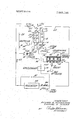
- FIG. is a schematic view of the system.
- the invention is intended for a hydrogen-oxygen cell in which hydrogen as the fuel and oxygen combine to form water the Bacon-type cell, using porous nickel electrodes and with a trapped electrolyte. That is to say, the electrolyte is located between the two electrodes and is not circulated into and out of the cell.
- a single hydrogen-oxygen cell having a trapped electrolyte 2 located between electrodes 4 and 6.
- the hydrogen electrode 4 is located between the electrolyte and a hydrogen chamber 8 into which hydrogen gas is delivered through an inlet 10.
- the oxygen electrode 6 is located between the electrolyte and a chamber 12 into which oxygen is delivered under pressure through an inlet 14. Excess oxygen escapes through an outlet 16 and excess hydrogen and water vapor escapes through an outlet 18.
- the cell is located in an enclosing housing 20 which may be of insulating material so that the electrodes are insulated from one another and electricity is delivered to leads 22.
- a cold plate 24 by which heat removal from the cell is effected.
- This plate has a coolant passage 26 therein connected into an auxiliary coolant circuit 28 which includes a modulating valve 30 and a circulating pump 32, the latter circulating the coolant through the circuit.
- a motor 34 drives the pump preferably at a constant speed during cell operation.
- auxiliary cooling circuit or conduit 28 Associated with the auxiliary cooling circuit or conduit 28 is a cooperating main cooling circuit 36 that taps into circuit 28 at a connection 38 downstream of the outlet forv the cooling fluid from the cell (the flow being in the direction of the arrow 40). From the connection 38 coolant flows through circuit 36 in the direction of arrow 42 to a radiator 44 and thence past a modulating valve 46 and through a coil 48 associated with a condenser 50 to the modulating valve 30.
- This valve is temperature responsive being actuated from a temperature sensing element 52 preferably located adjacent to the cold plate 24.
- the sensed temperature operates through a controller 54 to an actuator 56 for the valve, thereby moving the valve 30 to control the quantity of coolant entering the auxiliary circuit 28 from the main circuit, the arrangement being designed to maintain a constant temperature at the sensor 52 by increasing the flow from circuit 36 if the coolant temperature begins to increase.
- the coolant entering valve 30 from circuit 36 is cooler than the coolant in the auxiliary circuit 28, as will become apparent.
- the condenser 50 is a porous plate condenser in which a porous plate 58 forms the dividing wall between two chambers 60 and 62.
- the chamber 60 which is defined by a ribbed plate 61, as shown, is filled with water and is cooled by the coil 48.
- the chamber 62 receives hydrogen gas and water vapor from the fuel cell through the circuit 64 from the hydrogen outlet 18 through the condenser to a pump 66 and thence to the hydrogen inlet 10. Additional hydrogen is added to the circuit adjacent the outlet 18 through a supply connection 68.
- the porous plate 58" is kept cool by the water in compartment 60 and by the contact with the ribs on the plate 61.
- the plate 58 condenses water from the hydrogen and water vapor in'chamber 62 onto the exposed surface of the plate.
- the gas pressure in chamber 62 forces the water through the plate as it is formed but the surface tension of the water prevents the escape of gas through the plate.
- the condensed water escapes through a relief valve 70 into a container 72.
- the relief valve 70 is set to maintain a pressure in compartment 60 that will permit water to flow through the porous plate but will prevent the flow of gas therethrough. This arrangement will work in a zero gravity environment since the condensed water is all on the plate surface and is forced through the plate by gas pressure.
- the temperature of the porous plate is maintained constant by a temperature sensing device'74 on the plate which conveys a temperature signal to a controller 76 which in turn activates a valve actuator 78 for valve 46.
- This valve serves to mix cooled coolant from the radiator with uncooled coolant flowing around the radiator through a bypass conduit 80 and thereby maintains a substantially constant temperature at plate 58.
- the valve 46 will be moved to increase the proportion of coolant from the radiator flowing through the valve thus serving to lower the coolant temperature in chamber 60 and lowering the plate temperature. 7
- the pressures of the hydrogen and oxygen entering the cell are controlled in a well-known manner.
- hydrogen is forced into the chamber 8 and flows therethrough in the same direction as the coolant in plate 24.
- a part of the hydrogen and oxygen gases flowing through the pores of the electrodes produces electricity with a resultant increase in temperature of the cell until design temperature is reached.
- the hydrogen and oxygen inlet pressures are 65 p.s.i. and the nominal operating cell temperature is 182 F. Due to the large heat transfer area and low thermal resistance between the coolant in passage 26, the adjacent plate 24, the electrode 4, and the electrolyte 2, coolant and electrolyte temperature are nearly identical. Assume the temperature of the coolant entering the cell is l70 F. and thus, by the above statement, the electrolyte temperature at the inlet to the cell is nearly F. Assume also that the saturation temperature of the hydrogen-water vapor mixture leaving the condenser and entering the cell is 150 F. The above combination of electrolyte temperature and hydrogen saturation temperature specifies a given electrolyte concentration and volume. As the coolant passes through the cell it picks up heat and may leave the cell at 195 F. Thus the electrolyte temperature at the outlet end of the cell is very near 195 F. If the ratio of hydrogen to coolant mass rates are properly specified in design, the
- the condenser which receives hydrogen and water vapor at a saturation temperature of 175 F. condenses out the water vapor and cools the hydrogen to a saturation temperature of 150 F.
- the drop in pressure in hydrogen circuit 64 is made up by the pump 66.
- the coolant leaving the cell is, in 'part, circulated through the radiator 44 which drops the temperature to 70 F. or ambient, in part through the auxiliary coolant circuit 28 in the direction of the arrow 81, and in part around the radiator through bypass 80 as determined by valves 30 and 46 such that the inlet temperature of the coolant entering the condenser is 120 F.
- the coolant leaving the condenser may be at 145 F. and is mixed with the coolant in circuit 28 at valve 30 so that the coolant entering the cold plate is again l70 F.
- temperatures and pressures of the system will be adjusted accordingly.
- the temperature sensing devices are well known commercially available devices as are the controllers and modulating valves and the actuators for the valves.
- the hydrogen circuit thus functions primarily for picking up water vapor from the cell and delivering it to the condenser and is not utilized primarily for maintaining cell temperature.
- the coolant circuit is independent of the hydrogen circuit and thus may utilize a more effective coolant than hydrogen and by appropriate flow will provide most efficient heat removal from the cell. This system avoids the need for a circulating electrolyte.
- This system possesses the capability of maintaining electrolyte volume constant with changes in electrical load on the fuel cell. Under condition of a load increase on the cell, both the leaving coolant temperature and the leaving saturation temperature of the hydrogen will increase by the same increment. Thus the difference between these quantities remains unchanged and consequently the electrolyte volume remains constant as required by a capillary cell.
- a porous plate condenser-separator for removal of water vapor from a mixture of a gas and water vapor, the condenserseparator comprising adjacent chambers having a dividing wall in the form of a porous plate, cooling means for one chamber, means for supplying a coolant to said cooling means, a temperature sensor cooperating with the means for supplying the coolant to said cooling means for maintaining the porous plate at an essentially constant temperature, the chamber having the cooling means being filled with water, means for supplying a gas and water mixture to the other chamber for condensation of the water vapor on the porous plate, the porosity of the plate being such that the pressures in the chambers will cause the condensed water to flow through the plate but will not permit the flow of gas therethrough by reason of the surface tension of the water, and means for removing water from the chamber having the cooling means said means for removing the condensed water including a relief valve set to maintain a preselected pressure value within the chamber.
Landscapes
- Life Sciences & Earth Sciences (AREA)
- Engineering & Computer Science (AREA)
- Manufacturing & Machinery (AREA)
- Sustainable Development (AREA)
- Sustainable Energy (AREA)
- Chemical & Material Sciences (AREA)
- Chemical Kinetics & Catalysis (AREA)
- Electrochemistry (AREA)
- General Chemical & Material Sciences (AREA)
- Fuel Cell (AREA)
Abstract
A porous plate condenser-separator is disclosed providing means of removing water vapor from a fuel cell anode effluent stream. Water vapor condenses on a porous plate and is forced through the plate by virtue of an applied pressure differential. The condensed or liquified water escapes through a relief valve into a reservoir container. This device is useful in a zero gravity environment since water vapor condenses on the porous plate surface and is forced through the plate by gas pressure.
Description
United States Patent lnventors Richard G. Huebscher 2 Claims, 1 Drawing Fig.
us. c1. 165/35, 62/272, 165/107, 165/111, 165/164, 165/168 Int. Cl G051! 23/13; F28b 01/02 *Fle'ld Search 165/110,
[56} References Cited UNITED STATES PATENTS 2,361,854 10/1 944 McCormack 62/506X 2,386,889 l0/1945 Furry 165/168X 3,168,137 2/ l965 Smith 165/110 3,170,512 2/1965 Smith 165/110 3,314,475 4/1967 Valyi 165/18OX Primary Examiner-Albert W. Davis, Jr. Attorney-Charles A. Warren ABSTRACT: A porous plate condenser-separator is disclosed providing means of removing water vapor from a fuel cell anode efi'luent stream. Water vapor condenses on a porous plate and is forced through the plate by virtue of an applied pressure differential. The condensed or liquified water escapes through a relief valve into a reservoir container. This device is useful in a zero gravity environment since water vapor condenses on the porous plate surface and is forced through the plate by gas pressure.
can/mvzzfz J? Paemr mtgsssgrgseg ess POROUS PLATE CONDENSERSEPARATOR This invention relates to a system for controlling the output of a fuel cell and more particularly to a system for the removal of heat and water vapor from a cell during cell operation.
One feature of the invention is the use of a heat removal system that functions independently of the humidity removal system. Another feature is the removal of water by the circulation of an excess of hydrogen in which the vapor removal is proportional to the temperature rise in the electrolyte.
A primary feature of the system is its ability to maintain the electrolyte volume within the cell between close limits in order to prevent cell drying or cell flooding with consequent degradation in electrical performance. Cell flooding may result in loss of electrolyte from the battery to external plumbing and cell drying may result in internal mixing of the hydrogen and oxygen gases which in the presence of the electrode may result in cell destruction by burning".
One particular feature is the so-called loop system in which the-coolant for the cell is circulated through a circuit that cooperates with the hydrogen circulating circuit but in which there is no fluid flow between the two circuits.
Other features and advantages will be apparent from the specification and claims, and from the accompanying drawing which illustrates an embodiment of the invention.
The single FIG. is a schematic view of the system.
The invention is intended for a hydrogen-oxygen cell in which hydrogen as the fuel and oxygen combine to form water the Bacon-type cell, using porous nickel electrodes and with a trapped electrolyte. That is to say, the electrolyte is located between the two electrodes and is not circulated into and out of the cell. r v
Referring to the drawing, a single hydrogen-oxygen cell is shown, having a trapped electrolyte 2 located between electrodes 4 and 6. The hydrogen electrode 4 is located between the electrolyte and a hydrogen chamber 8 into which hydrogen gas is delivered through an inlet 10. The oxygen electrode 6 is located between the electrolyte and a chamber 12 into which oxygen is delivered under pressure through an inlet 14. Excess oxygen escapes through an outlet 16 and excess hydrogen and water vapor escapes through an outlet 18.
The cell is located in an enclosing housing 20 which may be of insulating material so that the electrodes are insulated from one another and electricity is delivered to leads 22. Within the housing and adjacent to the wall of hydrogen chamber 8 is a cold plate 24 by which heat removal from the cell is effected. This plate has a coolant passage 26 therein connected into an auxiliary coolant circuit 28 which includes a modulating valve 30 and a circulating pump 32, the latter circulating the coolant through the circuit. A motor 34 drives the pump preferably at a constant speed during cell operation.
Associated with the auxiliary cooling circuit or conduit 28 is a cooperating main cooling circuit 36 that taps into circuit 28 at a connection 38 downstream of the outlet forv the cooling fluid from the cell (the flow being in the direction of the arrow 40). From the connection 38 coolant flows through circuit 36 in the direction of arrow 42 to a radiator 44 and thence past a modulating valve 46 and through a coil 48 associated with a condenser 50 to the modulating valve 30. This valve is temperature responsive being actuated from a temperature sensing element 52 preferably located adjacent to the cold plate 24. The sensed temperature operates through a controller 54 to an actuator 56 for the valve, thereby moving the valve 30 to control the quantity of coolant entering the auxiliary circuit 28 from the main circuit, the arrangement being designed to maintain a constant temperature at the sensor 52 by increasing the flow from circuit 36 if the coolant temperature begins to increase. The coolant entering valve 30 from circuit 36is cooler than the coolant in the auxiliary circuit 28, as will become apparent.
The condenser 50 is a porous plate condenser in which a porous plate 58 forms the dividing wall between two chambers 60 and 62. The chamber 60 which is defined by a ribbed plate 61, as shown, is filled with water and is cooled by the coil 48.
The chamber 62 receives hydrogen gas and water vapor from the fuel cell through the circuit 64 from the hydrogen outlet 18 through the condenser to a pump 66 and thence to the hydrogen inlet 10. Additional hydrogen is added to the circuit adjacent the outlet 18 through a supply connection 68.
The porous plate 58"is kept cool by the water in compartment 60 and by the contact with the ribs on the plate 61. The plate 58 condenses water from the hydrogen and water vapor in'chamber 62 onto the exposed surface of the plate. The gas pressure in chamber 62 forces the water through the plate as it is formed but the surface tension of the water prevents the escape of gas through the plate. The condensed water escapes through a relief valve 70 into a container 72. The relief valve 70 is set to maintain a pressure in compartment 60 that will permit water to flow through the porous plate but will prevent the flow of gas therethrough. This arrangement will work in a zero gravity environment since the condensed water is all on the plate surface and is forced through the plate by gas pressure.
The temperature of the porous plate is maintained constant by a temperature sensing device'74 on the plate which conveys a temperature signal to a controller 76 which in turn activates a valve actuator 78 for valve 46. This valve serves to mix cooled coolant from the radiator with uncooled coolant flowing around the radiator through a bypass conduit 80 and thereby maintains a substantially constant temperature at plate 58. Obviously, if the plate temperature at 74 increases, the valve 46 will be moved to increase the proportion of coolant from the radiator flowing through the valve thus serving to lower the coolant temperature in chamber 60 and lowering the plate temperature. 7
In operation, the pressures of the hydrogen and oxygen entering the cell are controlled in a well-known manner. With motor 34 operating, hydrogen is forced into the chamber 8 and flows therethrough in the same direction as the coolant in plate 24. A part of the hydrogen and oxygen gases flowing through the pores of the electrodes produces electricity with a resultant increase in temperature of the cell until design temperature is reached.
Assume the hydrogen and oxygen inlet pressures are 65 p.s.i. and the nominal operating cell temperature is 182 F. Due to the large heat transfer area and low thermal resistance between the coolant in passage 26, the adjacent plate 24, the electrode 4, and the electrolyte 2, coolant and electrolyte temperature are nearly identical. Assume the temperature of the coolant entering the cell is l70 F. and thus, by the above statement, the electrolyte temperature at the inlet to the cell is nearly F. Assume also that the saturation temperature of the hydrogen-water vapor mixture leaving the condenser and entering the cell is 150 F. The above combination of electrolyte temperature and hydrogen saturation temperature specifies a given electrolyte concentration and volume. As the coolant passes through the cell it picks up heat and may leave the cell at 195 F. Thus the electrolyte temperature at the outlet end of the cell is very near 195 F. If the ratio of hydrogen to coolant mass rates are properly specified in design, the
:vapor pressure of the water in the hydrogen stream at the outlet of the cell is at a saturation temperature of F. With both coolant and hydrogen flowing in the same direction, the differential between the coolant temperature and the saturation temperature of thehydrogen remains essentially constant and specifies constant electrolyte concentration and volume as well as constant water removal rate from the inlet end to the outlet end of the cell.
The condenser, which receives hydrogen and water vapor at a saturation temperature of 175 F. condenses out the water vapor and cools the hydrogen to a saturation temperature of 150 F. The drop in pressure in hydrogen circuit 64 is made up by the pump 66.
The coolant leaving the cell is, in 'part, circulated through the radiator 44 which drops the temperature to 70 F. or ambient, in part through the auxiliary coolant circuit 28 in the direction of the arrow 81, and in part around the radiator through bypass 80 as determined by valves 30 and 46 such that the inlet temperature of the coolant entering the condenser is 120 F. The coolant leaving the condenser may be at 145 F. and is mixed with the coolant in circuit 28 at valve 30 so that the coolant entering the cold plate is again l70 F.
Although specific operating temperatures have been given, it is understood that this is merely exemplary since the fuel cell used may be a higher or lower pressure or higher or lower temperature cell in which event the temperatures and pressures of the system will be adjusted accordingly. The temperature sensing devices are well known commercially available devices as are the controllers and modulating valves and the actuators for the valves.
Obviously, as the hydrogen gas is circulated through the cell, it will pick up water vapor in proportion to the temperature rise of the electrolyte as established by the temperature rise of the coolant.
The hydrogen circuit thus functions primarily for picking up water vapor from the cell and delivering it to the condenser and is not utilized primarily for maintaining cell temperature. The coolant circuit is independent of the hydrogen circuit and thus may utilize a more effective coolant than hydrogen and by appropriate flow will provide most efficient heat removal from the cell. This system avoids the need for a circulating electrolyte.
This system possesses the capability of maintaining electrolyte volume constant with changes in electrical load on the fuel cell. Under condition of a load increase on the cell, both the leaving coolant temperature and the leaving saturation temperature of the hydrogen will increase by the same increment. Thus the difference between these quantities remains unchanged and consequently the electrolyte volume remains constant as required by a capillary cell.
It is to be understood that the invention is not limited to the specific embodiment herein illustrated and described, but may be used in other ways without departure from its spirit as defined by the following claims.
We claim:
1. A porous plate condenser-separator for removal of water vapor from a mixture of a gas and water vapor, the condenserseparator comprising adjacent chambers having a dividing wall in the form of a porous plate, cooling means for one chamber, means for supplying a coolant to said cooling means, a temperature sensor cooperating with the means for supplying the coolant to said cooling means for maintaining the porous plate at an essentially constant temperature, the chamber having the cooling means being filled with water, means for supplying a gas and water mixture to the other chamber for condensation of the water vapor on the porous plate, the porosity of the plate being such that the pressures in the chambers will cause the condensed water to flow through the plate but will not permit the flow of gas therethrough by reason of the surface tension of the water, and means for removing water from the chamber having the cooling means said means for removing the condensed water including a relief valve set to maintain a preselected pressure value within the chamber.
2. A condenser-separator as in claim 1, wherein water vapor is removed from a mixture of hydrogen and water vapor.
Claims (2)
1. A porous plate condenser-separator for removal of water vapor from a mixture of a gas and water vapor, the condenser-separator comprising adjacent chambers having a dividing wall in the form of a porous plate, cooling means for one chamber, means for supplying a coolant to said cooling means, a temperature sensor cooperating with the means for supplying the coolant to said cooling means for maintaining the porous plate at an essentially constant temperature, the chamber having the cooling means being filled with water, means for supplying a gas and water mixture to the other chamber for condensation of the water vapor on the porous plate, the porosity of the plate being such that the pressures in the chambers will cause the condensed water to flow through the plate but will not permit the flow of gas therethrough by reason of the surface tension of the water, and means for removing water from the chamber having the cooling means said means for removing the condensed water including a relief valve set to maintain a preselected pressure value within the chamber.
2. A condenser-separator as in claim 1, wherein water vapor is removed from a mixture of hydrogen and water vapor.
Applications Claiming Priority (2)
| Application Number | Priority Date | Filing Date | Title |
|---|---|---|---|
| US52427566A | 1966-02-01 | 1966-02-01 | |
| US81684668A | 1968-06-28 | 1968-06-28 |
Publications (1)
| Publication Number | Publication Date |
|---|---|
| US3565166A true US3565166A (en) | 1971-02-23 |
Family
ID=27061448
Family Applications (2)
| Application Number | Title | Priority Date | Filing Date |
|---|---|---|---|
| US524275A Expired - Lifetime US3455743A (en) | 1966-02-01 | 1966-02-01 | Fuel cell with heat and water vapor removing means |
| US816846*A Expired - Lifetime US3565166A (en) | 1966-02-01 | 1968-06-28 | Porous plate condenser-separator |
Family Applications Before (1)
| Application Number | Title | Priority Date | Filing Date |
|---|---|---|---|
| US524275A Expired - Lifetime US3455743A (en) | 1966-02-01 | 1966-02-01 | Fuel cell with heat and water vapor removing means |
Country Status (5)
| Country | Link |
|---|---|
| US (2) | US3455743A (en) |
| CH (1) | CH476402A (en) |
| DE (1) | DE1671955B2 (en) |
| FR (1) | FR1517027A (en) |
| GB (1) | GB1177273A (en) |
Cited By (11)
| Publication number | Priority date | Publication date | Assignee | Title |
|---|---|---|---|---|
| US4274480A (en) * | 1978-09-25 | 1981-06-23 | Mcgee Joseph R | Gas chromatograph sample conditioner |
| US4383415A (en) * | 1979-12-04 | 1983-05-17 | Jacob Carlyle W | Refrigeration and water condensate removal apparatus |
| EP0287035A3 (en) * | 1987-04-16 | 1989-02-08 | International Fuel Cells Corporation | Separation of gaseous hydrogen from a water-hydrogen mixture in a fuel cell power system operating in a weightless environment |
| WO2000059059A1 (en) * | 1999-03-26 | 2000-10-05 | Siemens Aktiengesellschaft | Method for operating a fuel cell installation and a fuel cell installation |
| US20030118880A1 (en) * | 2001-11-28 | 2003-06-26 | Ballard Power Systems | Evaporative edge cooling of a fuel cell |
| US20040001984A1 (en) * | 2002-06-28 | 2004-01-01 | Julio Alva | Fuel cell cooling system for low coolant flow rate |
| US20050211842A1 (en) * | 2003-11-27 | 2005-09-29 | Airbus Deutschland Gmbh | Arrangement and method for the generation of water on board an aircraft |
| US20070037027A1 (en) * | 2003-09-19 | 2007-02-15 | Atsushi Oma | Fuel cell power plant |
| US20090158928A1 (en) * | 2007-12-19 | 2009-06-25 | Whirlpool Corporation | Squeezable moisture removal device |
| WO2012030368A1 (en) * | 2010-09-01 | 2012-03-08 | Lawrence Curtin | Application of radio frequency to fluidized beds |
| US11993403B2 (en) * | 2018-05-24 | 2024-05-28 | The Boeing Company | Advanced cooling for cryogenic powered vehicles |
Families Citing this family (25)
| Publication number | Priority date | Publication date | Assignee | Title |
|---|---|---|---|---|
| AT277342B (en) * | 1967-03-21 | 1969-12-29 | Siemens Ag | Process and device for the joint removal of heat loss and water of reaction from fuel elements |
| US3498844A (en) * | 1967-08-21 | 1970-03-03 | United Aircraft Corp | Fuel cell waste heat and water removal system |
| US3537905A (en) * | 1968-05-09 | 1970-11-03 | Elektrometallurgie Gmbh | Fuel cell unit liquid electrolyte conditioner and method |
| US3664873A (en) * | 1969-04-21 | 1972-05-23 | United Aircraft Corp | Self-regulating encapsulated fuel cell system |
| BE797314A (en) * | 1972-03-28 | 1973-07-16 | Licentia Gmbh | FUEL BATTERY SYSTEM |
| US3964930A (en) * | 1975-07-21 | 1976-06-22 | United Technologies Corporation | Fuel cell cooling system |
| IL49872A (en) * | 1975-07-21 | 1978-07-31 | United Technologies Corp | Fuel cell cooling system using a non-dielectric coolant |
| US4192906A (en) * | 1978-07-10 | 1980-03-11 | Energy Research Corporation | Electrochemical cell operation and system |
| US4582765A (en) * | 1981-08-25 | 1986-04-15 | The United States Of America As Represented By The United States Department Of Energy | Fuel cell system with coolant flow reversal |
| US4362789A (en) * | 1981-09-21 | 1982-12-07 | Westinghouse Electric Corp. | Fuel cell cooling and recirculation system |
| US4722873A (en) * | 1985-12-06 | 1988-02-02 | Mitsubishi Denki Kabushiki Kaisha | Fuel cell power generating system |
| JPH0732895Y2 (en) * | 1988-06-23 | 1995-07-31 | アイシン精機株式会社 | Condensate removal device for gas heat pump |
| DE59306256D1 (en) * | 1992-11-05 | 1997-05-28 | Siemens Ag | Method and device for water and / or inert gas disposal of a fuel cell block |
| JPH1131520A (en) * | 1997-05-13 | 1999-02-02 | Mazda Motor Corp | Polymer electrolyte fuel cell |
| US6013385A (en) * | 1997-07-25 | 2000-01-11 | Emprise Corporation | Fuel cell gas management system |
| DE19802490C2 (en) * | 1998-01-23 | 2002-01-24 | Xcellsis Gmbh | Use of a paraffin as a coolant for fuel cells |
| US6780227B2 (en) * | 2000-10-13 | 2004-08-24 | Emprise Technology Associates Corp. | Method of species exchange and an apparatus therefore |
| JP4374782B2 (en) * | 2001-01-18 | 2009-12-02 | トヨタ自動車株式会社 | In-vehicle fuel cell system and control method thereof |
| DE102004036296B4 (en) * | 2004-07-27 | 2010-04-01 | Airbus Deutschland Gmbh | Draining device for an aircraft |
| US8679659B2 (en) * | 2009-10-21 | 2014-03-25 | GM Global Technology Operations LLC | Temperature control of a vehicle battery |
| US11211619B2 (en) | 2019-10-11 | 2021-12-28 | GM Global Technology Operations LLC | Fuel cell architectures, aftertreatment systems, and control logic for exhaust water extraction |
| US11597255B2 (en) * | 2020-03-25 | 2023-03-07 | Pony Al Inc. | Systems and methods for cooling vehicle components |
| US11728496B2 (en) | 2021-03-09 | 2023-08-15 | GM Global Technology Operations LLC | Propulsion battery packs with integrated fuel tank mounting systems |
| US12315977B2 (en) | 2021-11-01 | 2025-05-27 | GM Global Technology Operations LLC | Shock-force mitigation systems and methods for electrochemical fuel cell stacks |
| US11735751B1 (en) | 2022-03-21 | 2023-08-22 | GM Global Technology Operations LLC | Intelligent fuel cell systems and control logic for smart use of anode header drain valves for FCS bleed and drainage |
Citations (5)
| Publication number | Priority date | Publication date | Assignee | Title |
|---|---|---|---|---|
| US2361854A (en) * | 1940-12-27 | 1944-10-31 | Gen Motors Corp | Refrigerating apparatus |
| US2386889A (en) * | 1940-08-02 | 1945-10-16 | Outboard Marine & Mfg Co | Coil assembly |
| US3168137A (en) * | 1963-03-29 | 1965-02-02 | Carrier Corp | Heat exchanger |
| US3170512A (en) * | 1963-03-29 | 1965-02-23 | Carrier Corp | Heat exchanger |
| US3314475A (en) * | 1965-05-14 | 1967-04-18 | Olin Mathieson | Composite structure |
Family Cites Families (6)
| Publication number | Priority date | Publication date | Assignee | Title |
|---|---|---|---|---|
| NL259578A (en) * | 1959-12-31 | 1900-01-01 | ||
| US3172784A (en) * | 1961-08-18 | 1965-03-09 | Gen Electric | Methods and apparatus for removing heat and water from a fuel cell |
| NL285988A (en) * | 1961-11-30 | |||
| US3253957A (en) * | 1962-02-28 | 1966-05-31 | United Aircraft Corp | Fuel cell with control responsive to temperature changes |
| US3370984A (en) * | 1963-08-09 | 1968-02-27 | Allis Chalmers Mfg Co | Static vapor control for fuel cells |
| US3379572A (en) * | 1964-08-04 | 1968-04-23 | United Aircraft Corp | Method and apparatus for limiting the output voltage of a fuel cell |
-
1966
- 1966-02-01 US US524275A patent/US3455743A/en not_active Expired - Lifetime
-
1967
- 1967-01-16 DE DE1967U0013459 patent/DE1671955B2/en active Granted
- 1967-01-27 GB GB4282/67A patent/GB1177273A/en not_active Expired
- 1967-01-28 CH CH127767A patent/CH476402A/en not_active IP Right Cessation
- 1967-01-31 FR FR5051A patent/FR1517027A/en not_active Expired
-
1968
- 1968-06-28 US US816846*A patent/US3565166A/en not_active Expired - Lifetime
Patent Citations (5)
| Publication number | Priority date | Publication date | Assignee | Title |
|---|---|---|---|---|
| US2386889A (en) * | 1940-08-02 | 1945-10-16 | Outboard Marine & Mfg Co | Coil assembly |
| US2361854A (en) * | 1940-12-27 | 1944-10-31 | Gen Motors Corp | Refrigerating apparatus |
| US3168137A (en) * | 1963-03-29 | 1965-02-02 | Carrier Corp | Heat exchanger |
| US3170512A (en) * | 1963-03-29 | 1965-02-23 | Carrier Corp | Heat exchanger |
| US3314475A (en) * | 1965-05-14 | 1967-04-18 | Olin Mathieson | Composite structure |
Cited By (13)
| Publication number | Priority date | Publication date | Assignee | Title |
|---|---|---|---|---|
| US4274480A (en) * | 1978-09-25 | 1981-06-23 | Mcgee Joseph R | Gas chromatograph sample conditioner |
| US4383415A (en) * | 1979-12-04 | 1983-05-17 | Jacob Carlyle W | Refrigeration and water condensate removal apparatus |
| EP0287035A3 (en) * | 1987-04-16 | 1989-02-08 | International Fuel Cells Corporation | Separation of gaseous hydrogen from a water-hydrogen mixture in a fuel cell power system operating in a weightless environment |
| WO2000059059A1 (en) * | 1999-03-26 | 2000-10-05 | Siemens Aktiengesellschaft | Method for operating a fuel cell installation and a fuel cell installation |
| US20030118880A1 (en) * | 2001-11-28 | 2003-06-26 | Ballard Power Systems | Evaporative edge cooling of a fuel cell |
| WO2004004041A1 (en) * | 2002-06-28 | 2004-01-08 | Hydrogenics Corporation | Fuel cell cooling system for low coolant flow rate |
| US20040001984A1 (en) * | 2002-06-28 | 2004-01-01 | Julio Alva | Fuel cell cooling system for low coolant flow rate |
| US20070037027A1 (en) * | 2003-09-19 | 2007-02-15 | Atsushi Oma | Fuel cell power plant |
| US20050211842A1 (en) * | 2003-11-27 | 2005-09-29 | Airbus Deutschland Gmbh | Arrangement and method for the generation of water on board an aircraft |
| US7108229B2 (en) * | 2003-11-27 | 2006-09-19 | Airbus Deutschland Gmbh | Arrangement and method for the generation of water on board an aircraft |
| US20090158928A1 (en) * | 2007-12-19 | 2009-06-25 | Whirlpool Corporation | Squeezable moisture removal device |
| WO2012030368A1 (en) * | 2010-09-01 | 2012-03-08 | Lawrence Curtin | Application of radio frequency to fluidized beds |
| US11993403B2 (en) * | 2018-05-24 | 2024-05-28 | The Boeing Company | Advanced cooling for cryogenic powered vehicles |
Also Published As
| Publication number | Publication date |
|---|---|
| GB1177273A (en) | 1970-01-07 |
| CH476402A (en) | 1969-07-31 |
| US3455743A (en) | 1969-07-15 |
| FR1517027A (en) | 1968-02-05 |
| DE1671955A1 (en) | 1972-04-06 |
| DE1671955B2 (en) | 1976-07-22 |
Similar Documents
| Publication | Publication Date | Title |
|---|---|---|
| US3565166A (en) | Porous plate condenser-separator | |
| CA1067852A (en) | Electrolysis cell system | |
| US7051801B1 (en) | Method and apparatus for humidification and temperature control of incoming fuel cell process gas | |
| US3905884A (en) | Electrolysis cell system including recirculating product gas stream for cooling the cell | |
| GB945223A (en) | Improvements in or relating to refrigerators | |
| US3583685A (en) | Method and apparatus for controlling quantity of a vapor in a gas | |
| US3198664A (en) | Fuel cell system | |
| US3053056A (en) | Absorption refrigeration systems and control arrangements therefor | |
| JP2007512675A (en) | Method and apparatus for humidification control of energy recovery device in fuel cell power plant | |
| US3300341A (en) | Fuel cell heat and water removal system using electrolyte circulation | |
| US2254917A (en) | Cooling system for electric devices | |
| US3479224A (en) | Valve for continuous removal of reaction water from a fuel cell | |
| US3470702A (en) | Apparatus for regulating humidity in a climatic chamber and method of operating the same | |
| US3552135A (en) | Fluid cooling arrangement employing liquified gas | |
| US3959019A (en) | Fuel cell | |
| US3956013A (en) | Fuel cell | |
| US3956016A (en) | Fuel cell | |
| JPS5516487A (en) | Superconductive equipment | |
| US1985511A (en) | Electric current rectifier | |
| JPS591626A (en) | Moistening method for atmosphere gas | |
| US2635039A (en) | Apparatus for purifying products of combustion | |
| US3957536A (en) | Fuel cell | |
| JPH0248783Y2 (en) | ||
| JPH0248784Y2 (en) | ||
| US3296029A (en) | Fuel cell system for the automatic control of cell temperature |