US3561663A - Apparatus for producing sheet metal plates having reinforcing members welded thereon - Google Patents
Apparatus for producing sheet metal plates having reinforcing members welded thereon Download PDFInfo
- Publication number
- US3561663A US3561663A US699483A US3561663DA US3561663A US 3561663 A US3561663 A US 3561663A US 699483 A US699483 A US 699483A US 3561663D A US3561663D A US 3561663DA US 3561663 A US3561663 A US 3561663A
- Authority
- US
- United States
- Prior art keywords
- members
- welding
- sheet metal
- reinforcing members
- reinforcing
- Prior art date
- Legal status (The legal status is an assumption and is not a legal conclusion. Google has not performed a legal analysis and makes no representation as to the accuracy of the status listed.)
- Expired - Lifetime
Links
- 230000003014 reinforcing effect Effects 0.000 title claims abstract description 75
- 239000002184 metal Substances 0.000 title claims abstract description 41
- 238000003466 welding Methods 0.000 claims abstract description 65
- 238000006073 displacement reaction Methods 0.000 claims description 2
- 230000008646 thermal stress Effects 0.000 description 2
- 230000008878 coupling Effects 0.000 description 1
- 238000010168 coupling process Methods 0.000 description 1
- 238000005859 coupling reaction Methods 0.000 description 1
- 238000010586 diagram Methods 0.000 description 1
- 238000009499 grossing Methods 0.000 description 1
- 230000004048 modification Effects 0.000 description 1
- 238000012986 modification Methods 0.000 description 1
Images


Classifications
-
- B—PERFORMING OPERATIONS; TRANSPORTING
- B23—MACHINE TOOLS; METAL-WORKING NOT OTHERWISE PROVIDED FOR
- B23K—SOLDERING OR UNSOLDERING; WELDING; CLADDING OR PLATING BY SOLDERING OR WELDING; CUTTING BY APPLYING HEAT LOCALLY, e.g. FLAME CUTTING; WORKING BY LASER BEAM
- B23K9/00—Arc welding or cutting
- B23K9/02—Seam welding; Backing means; Inserts
- B23K9/025—Seam welding; Backing means; Inserts for rectilinear seams
- B23K9/0256—Seam welding; Backing means; Inserts for rectilinear seams for welding ribs on plates
-
- B—PERFORMING OPERATIONS; TRANSPORTING
- B63—SHIPS OR OTHER WATERBORNE VESSELS; RELATED EQUIPMENT
- B63B—SHIPS OR OTHER WATERBORNE VESSELS; EQUIPMENT FOR SHIPPING
- B63B3/00—Hulls characterised by their structure or component parts
- B63B3/14—Hull parts
- B63B3/68—Panellings; Linings, e.g. for insulating purposes
-
- Y—GENERAL TAGGING OF NEW TECHNOLOGICAL DEVELOPMENTS; GENERAL TAGGING OF CROSS-SECTIONAL TECHNOLOGIES SPANNING OVER SEVERAL SECTIONS OF THE IPC; TECHNICAL SUBJECTS COVERED BY FORMER USPC CROSS-REFERENCE ART COLLECTIONS [XRACs] AND DIGESTS
- Y10—TECHNICAL SUBJECTS COVERED BY FORMER USPC
- Y10T—TECHNICAL SUBJECTS COVERED BY FORMER US CLASSIFICATION
- Y10T29/00—Metal working
- Y10T29/53—Means to assemble or disassemble
- Y10T29/53313—Means to interrelatedly feed plural work parts from plural sources without manual intervention
- Y10T29/53378—Means to interrelatedly feed plural work parts from plural sources without manual intervention including converging conveyors
-
- Y—GENERAL TAGGING OF NEW TECHNOLOGICAL DEVELOPMENTS; GENERAL TAGGING OF CROSS-SECTIONAL TECHNOLOGIES SPANNING OVER SEVERAL SECTIONS OF THE IPC; TECHNICAL SUBJECTS COVERED BY FORMER USPC CROSS-REFERENCE ART COLLECTIONS [XRACs] AND DIGESTS
- Y10—TECHNICAL SUBJECTS COVERED BY FORMER USPC
- Y10T—TECHNICAL SUBJECTS COVERED BY FORMER US CLASSIFICATION
- Y10T29/00—Metal working
- Y10T29/53—Means to assemble or disassemble
- Y10T29/53313—Means to interrelatedly feed plural work parts from plural sources without manual intervention
- Y10T29/53383—Means to interrelatedly feed plural work parts from plural sources without manual intervention and means to fasten work parts together
-
- Y—GENERAL TAGGING OF NEW TECHNOLOGICAL DEVELOPMENTS; GENERAL TAGGING OF CROSS-SECTIONAL TECHNOLOGIES SPANNING OVER SEVERAL SECTIONS OF THE IPC; TECHNICAL SUBJECTS COVERED BY FORMER USPC CROSS-REFERENCE ART COLLECTIONS [XRACs] AND DIGESTS
- Y10—TECHNICAL SUBJECTS COVERED BY FORMER USPC
- Y10T—TECHNICAL SUBJECTS COVERED BY FORMER US CLASSIFICATION
- Y10T29/00—Metal working
- Y10T29/53—Means to assemble or disassemble
- Y10T29/53796—Puller or pusher means, contained force multiplying operator
- Y10T29/5383—Puller or pusher means, contained force multiplying operator having fluid operator
Definitions
- SHEET 08 [1F 10 l/WEAVOK' ATTORNEYS PATENTEU FEB 9 19m SHKET 10 0F ⁇ g/ k AME/ 02 MMM M4 5% ATTORNEYS APPARATUS FOR PRODUCING SHEET METAL PLATES HAVING REINFORCING MEMBERS WELDED THEREON BACKGROUND OF THE INVENTION
- lifting devices have been used for mounting or positioning the reinforcing members on the sheet metal plates which are moved through the mounting station, being effected from above by means of the lifting devices.
- the invention has an object of providing an apparatus mount which eliminates the above-mentioned drawbacks and makes it possible to mount or position the reinforcing members on the sheet metal plates in a safe manner and to align and hold these reinforcing members on the plates in rapid ald reliable manner.
- the invention is based on the principle that stationary means must be provided in the mounting station for aligning and holding the reinforcing members, these stationary means being capable of applying comparatively great forces which are required, by simple and uncomplicated means.
- a device for aligning and clamping the reinforcing members would constitute an obstruction to lowering the latter into position from above, these reinforcing members must be introduced into the mounting station from the side, rather than from above.
- the present invention consists in an apparatus for producing sheet metal plates having reinforcing members welded thereon, particularly ribbed ships plates, comprising a feed device for the sheet metal plates anddevice for mounting or positioning the reinforcing members on the sheet metal plates prior to welding, said mounting or positioning device including clamping means, arranged in stationary manner in a mounting station, for said reinforcing members and of a feed device for horizontally moving the reinforcing members over a transverse guide which is located in the vicinity of a feed path for the sheet metal plate and extends transversely to the direction of feed of the sheet metal plate, so that the reinforcing members after leaving the transverse guide, slide over the sheet metal plate and reach their mounting position, welding means being provided in said mounting or positioning station for welding said reinforcing members to said sheet metal plates.
- the device for introducing the reinforcing members conveniently consists of a slide member which is capable of moving along the transverse guide and which is provided with a lug adapted to engage the trailing end of the reinforcing member.
- the latter advantageously consist of a channel section provided with supporting rollers in its bottom and with, at its sides, lateral guide rollers for engaging the reinforcing members, the latter being introduced into the channel section from above by means of a lifting device; the rails for supporting the slide member may be arranged in the side walls of the guide channel section and halfway up the latter.
- the clamping device in the assembly and welding station is conveniently provided with a bridge which freely extends above the whole width of the sheet metal plate; groups of adjustable clamping elements are arranged on this bridge and preferably consist of a group of downwardly-acting holding members and of a group of laterally-acting holding members.
- the downwardly-acting holding members are in the form of simple plungers which may be actuated hydraulically.
- the laterally-acting holding members may be in the form of pairs of oppositely movable clamping elements which engage both sides of the reinforcing member,
- the laterally-acting holding members are conveniently arranged on slide members which are movable up and down, are guided in the bridge, are forked in their lower region and engage the reinforcing member.
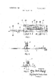
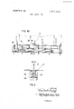
- FIG. 1 shows an elevation of the apparatus
- FIG. 2 is a cross section taken along the line II-Il of FIG. 1;
- FIG. 3 is an end view of the apparatus shown in FIG. 1, as seen from the right in the FIG.;
- FIG. 4 is an elevation of the slide member used in the device shown in FIG. 1 for introducing the reinforcing members
- FIG. 5 is a plan view of FIG. 4;
- FIG. 6 is an enlarged cross-sectional view through the channel for introducing the reinforcing elements, taken along the line VIVI ofFIG. 1;
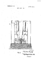
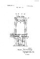
- FIG. 7 is a cross-sectional view through the assembly and clamping station of the apparatus, taken along the line VII-VII of FIG. 1, with a downwardly-acting securing member of the clamping equipment;
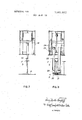
- FIG. 8 is a cross-sectional view through the assembly and clamping station, taken along the line VIII-VIII of FIG. 1, showing a laterally acting securing member of the clamping station;
- FIG. 9 is a cross section through a carriage provided for feeding the sheet metal part through the assembly and welding station.
- FIG. 10 is a device for placing the lower abutment for the sheet metal plate in the assembly station
- FIG. 11 is a cross section taken along the line XI-XI of FIG. 10;
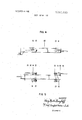
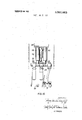
- FIG. 12 is an elevation of the device for shifting the laterally acting securing members
- FIG. 13 is a plan view of FIG. 12;
- FIG. 14 is an end view similar to that of FIG. 2, but enlarged and in greater detail;
- FIG. 15 is an enlarged partial side elevation of the welding head shown in FIG. 14.
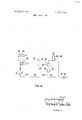
- FIG. 16 shows a circuit diagram for a pneumatic mechanism for shifting the welding head.
- the apparatus shown therein serves to produce sheet metal plates P having reinforcing members S welded thereto.
- the reinforcing members S may, for example consist of T-sections having an upper flange portion F (FIG. 2).
- the sheet metal plate P is moved in the direction p (FIG. 2) by a plate feeding means on a roller track I through an assembly or mounting and welding station 2, the movement being intermittent or stepwise, each step corresponding to the lateral distance A between the reinforcing members S.
- the feed device 3 for feeding the reinforcing members S comprises a transverse guide channel 4 (FIG. 6) which has supporting rollers 5 in its bottom and is provided at each of its sides with a group of guide rollers 6, 7, 8.
- the channel 4 is formed by a frame which is provided with pairs of columns 9 spaced apart from one another and serving as supports for the guide rollers 6, 7, 8.
- the reinforcing members Sa re lowered from above into the guide channel 4 by means of a mobile crane which is not shown in the drawing.
- the reinforcing member S introduced into the channel 4 is thrust, by a slide member 10 (FIG. 4) having a lug 11, in the direction S into the station 2, where, sliding over the plate P which has been advanced to the correct point, the member S reaches the correct position in relation to the plate P.
- the slide member 10 comprises a tubular support and is adapted to travel on U-shaped supporting rails 12, which are arranged in the supporting columns 9 of the guide channel 4.
- the slide member 10 is fitted with supporting rollers 13 and with lateral guide rollers 14.
- the slide member 10 is moved back and forth by an endless chain drive 15.
- FIGS. 4 and 5 only show the ends of the endless drive chain 15 which engage lugs 16 on the slide member 10.
- clamping device 17 There is further provided in the assembly and working station'2, for the purpose of properly aligning and securing the introduced reinforcing members S, an adjusting and clamping means which will hence forth be referredto as the clamping device 17 (FIG. 1).
- the clamping device 17 is supported by a bridge 18 (FIG. 7), which freely extends above the entire width of the sheet metal plate P and on which there are arranged two groups of adjustable clamping elements constituted by a group of downwardly-acting securing members 19 and a group of laterally-acting holding members 20 (FIG. 1).
- the downwardly-acting securing members 19 are in the form of hydraulically actuated plungers.
- the laterally-acting holding members20 are provided with oppositely movable pairs of clamping elements 21 (FIG. 8) which engage on the two opposite sides of the T-section reinforcing member S.
- the clamping elements 21 of the laterally-acting holding members 20 are arranged on slide members 22 which are movable up and down, are forked in their lower region and engage the reinforcing member S.
- the slide members 22 are movable up and down on pairs of rollers 23 in the supporting bridge 18 by means of a lifting chain 24.
- the clamping elements 21 are movable into or out of the clamping position by a hydraulic drives 25 (FIGS. 12 and 13).
- the device provided for positioning the clamping elements 21 is so formed that first of all one of the clamping elements, for example the left-hand clamping element 21 in FIG. 8, is pushed forward against the reinforcing member S by its hydraulic drive 25 until it abuts against a stop but adjustably rigidly attached to the slide member 22 and at the same time also pushes the reinforcing member S forward out of the position which it assumes when introduced into the assembly station 2, into the desired correct position.
- the right-hand clamping element 21 When the left-hand clamping element 21 has thus been brought into its required position of abutment, the right-hand clamping element 21 is pushed from the other side by its hydraulic drive 25 so as to press against the reinforcing member S but with somewhat reduced force so as to prevent any possibility of the left-hand clamping element 21 from disengagement with the reinforcing members S.
- the hydraulic drives 25 are provided with means enabling them to exert variable clamping pressures.
- FIGS. 12 and 13 show a device serving for hydraulically shifting the clamping elements 21. All the clamping elements 21 on the same side of the reinforcing member S are actuated by a common hydraulic linear piston drive 25,11 rocker 34 of which engages a carrier 35 for the clamping elements 21. while parallel movement of the support 35 is ensured by guide arms 36.
- the laterally acting holding members 20, with their clamping elements 21 When the laterally acting holding members 20, with their clamping elements 21, have aligned the reinforcing member 5. the downwardly-acting holding members 19 descend and press the reinforcing member S firmly onto the plate P. The laterally-acting holding members 20 with their clamping elements 21 are then released and raised into their inoperative position, so that-the welding seam is exposed for welding.
- the laterally-acting holding members 20 can be connected firmly together by means of continuous supports 28 which interconnect the arms of the forked slide members 22.
- the laterally-acting holding members 20 are thus arranged for common upwards and downwards movement.
- two synchronously driven feed clamps 29 are provided on one side, that is on the left hand side in FIG. 1, of the feed track 1. These clamps are intended to be actuated by a hydraulic cylinder 30 and are supported by carriages 31, which move on a rail 32 disposed in the direction of feed.
- the clamps 29 are adjustable transversely tothe direction of feed p, so as to align the plate P in the machine.
- a hydraulic positioning device 37 is provided for this purpose.
- a beam-shaped abutment 38 (FIG. 10), which extends over the entire length of the station 2 and is adjustable in height so as to compensate thermal stresses, occurring during welding, by prestressing the plates P.
- the height adjustment of the abutment 38 is effected by wedges 39 which are located below the abutment 38 and are movable by means of a hydraulic piston drive 40.
- the height of the abutment 38 is infinitely variable by means of the hydraulic drive.
- a welding carriage 41 (FIG. 14) is movable in the longitudinal direction on the bridge 18 of the clamping device 17,
- the carriage 41 comprises a transverse head, which is located over the bridge 18, and supporting membersfor the welding equipment and its drive means, these supporting members projecting downwardly on each side of the bridge 18 and being described in greater detail herein below.
- Two separate driving motors 46 and 47 are provided and the drive mechanism shaft 48 is adapted to be alternately connected to these motors by way of couplings. More specifically. there is provided a variable speed DC motor 46, by means of which the welding equipment can be moved, in the course of welding, with continuously adjustable, and relatively low, speed, and sliding armature motor 47 by means of which the welding equipment can be rapidly moved from the welding position to and from the point at which welding is to be effected. By actuation of the sliding armature it is possible shortly before the particular welding position has been reached, to switch over to low speed for the purpose of achieving a precise adjustment to the required welding position,
- variable speed DC motor 46 From which the working stroke of the welding equipment canbe performed by means of the variable speed DC motor 46.
- the welding equipment comprises welding heads 49 which are adjustable vertically and laterally and of which one is disposed on each side of the reinforcing member S to be welded on, these welding heads 49 carrying conventional welding tools 50, 51 to be applied on both sides of the weld seam.
- the welding head is carried by a first, substantially vertical linear piston drive 52, 53 (FIG. 15) and for this purpose is suspended in pivotable manner at 54 on the lower end of the piston rod 53 of the linear piston drive.
- Guide rods 55 of the welding head 49 run in roller guides 56.
- These roller guides 56 and the cylinder 52 of the vertical linear piston drive are suspended from a slide member 57, which is movable on rails 58 at the lower ends of the lateral supports of the carriage 41,
- the two linear piston drives 52, 53 and 58, 59 are driven pneumatically. Their circuit is shown in FIG. 16.
- the welding head 49 with its holder rests, in the region of the welding seam, with only part of its weight on the sheet metal plate P and is therefore provided with a pneumatic pressure relief device.
- the vertical linear piston 5 verse guide comprises a channel section provided at its bottom with supporting rollers and at its sides with lateral guide rollers for the reinforcing member, the latter being adapted to be inserted from above into the said channel section.
- the supply duct 60 provided for downwards travel in the welding position, contains a pressure reducing valve 64, while the other supply duct 61, provided for upwards movement, contains a control valve 65 which can be switched on or off.
- a choke 67 for smoothing pressure surges.
- the valve 65 which can be switched over electrically, is also provided with a pressure relief valve 68.
- the operating pressure is arranged to be such that the weight of the welding head 49, when travelling downwards, exceeds and overcomes the pneumatic pressure of 3 atmospheres, whereas when travelling upwards the gravitational force of the welding head is over come by the higher pressure of 6 atmospheres.
- an electrically operated reversing valve 72 is incorporated for reversing the direction of the horizontal movement.
- the downwardly-acting holding members and the laterally-acting holding members could be differently constructed'and, for example take the form of pressure pads. It would also be possible for the laterally-acting holding members not to be firmly interconnected, but to arrange them separate from one another so that they could be operated individually.
- the reinforcing members S could alternatively be 501 brought into the assembly and welding station 2 by auxiliary devices in the form of horizontally movable carriages.
- the above-described manner of introducing the reinforcing members S by simply pushing them over the sheet metal plate P has proved advantageous in practice and is distinguished by extreme simplicity of the apparatus.
- An apparatus for producing sheet metal plates having reinforcing members welded thereon comprising a transport channel section and in the side walls thereof.
- clamping means includes a group of downwardly acting holding members and a group a laterally-acting holding members.
- a beami shaped abutment is arranged within the feed path for the sheet metal plate, said abutment being adjustable in its height by T means of wedges which are arranged on its underside and are provided with drive means for their horizontal displacement.
- An apparatus as claimed in claim 10 with a welding carriage movably arranged on the bridge of the clamping device, lwherein two separate drive motors are provided to which a i drive mechanism shaft is alternately connectable by means of I clutches, one of said motors being a variable speed DC drive motor for effecting a variable speed movement during weld- 1 ing, and the other being a sliding armature motor for effecting v a rapid movement from and to the welding point.
- An apparatus as claimed in claim 10 with a welding head which is adjustable in height and laterally, wherein the welding head is carried by a first, substantially vertical, linear piston drive, whose other part is carried with the movable part of a second, substantially horizontal, linear piston drive s nowadaysrsdisthex sls csesiss
- a welding head which is adjustable in height and laterally, wherein the welding head is carried by a first, substantially vertical, linear piston drive, whose other part is carried with the movable part of a second, substantially horizontal, linear piston drive s nowadaysrsdisthex sls csesiss
Landscapes
- Engineering & Computer Science (AREA)
- Mechanical Engineering (AREA)
- Physics & Mathematics (AREA)
- Plasma & Fusion (AREA)
- Chemical & Material Sciences (AREA)
- Combustion & Propulsion (AREA)
- Ocean & Marine Engineering (AREA)
- Butt Welding And Welding Of Specific Article (AREA)
Abstract
This disclosure relates to an apparatus for producing sheet metal plates having reinforcing members welded thereon, particularly ribbed ship''s plates, of the kind comprising a feed device for the sheet metal plates, a device for mounting said reinforcing members on to the plates and means for welding said reinforcing member to said sheets.
Description
United States Patent [72] Inventor Heinz Martin Wenzlafi Am Groben Geeren 7-9, 2863 Ritterhude, Germany Germany [21] Appl. No. 699,483
[22] Filed Jan. 22, 1968 [45] Patented Feb. 9,1971
[32] Priority Feb. 4, 1967 [33] Germany [54] APPARATUS FOR PRODUCING SHEET METAL PLATES HAVING REINFORCING MEMBERS WELDED THEREON 18 Claims, 16 Drawing Figs.
[52] U.S. Cl 228/25, 29/200, 2 9/252; 219 /136; 2 28/30; [51] Int. Cl B23k 1/00, B23k 5/00 [50] Field of Search 228/25,
[56] References Cited UNITED STATES PATENTS 2,288,796 7/1942 Edwards 29/200 2,322,290 6/1943 Gabel 29/417 2,164,567 7/1939 Burke 228/6X 2,176,664 10/1939 Burke 219/161X Primary Examiner-John F. Campbell Assistant Examiner- Robert J. Craig Att0rneyWolf, Greenfield and Sacks ABSTRACT: This disclosure relates to an apparatus for producing sheet metal plates having reinforcing members welded thereon, particularly ribbed ships plates, of the kind comprising a feed device for the sheet metal plates, a device for mounting said reinforcing members on to the plates and means for welding said reinforcing member to said sheets.
i I HIIZZIIPSJ PATENTED FEB 9 1571 SHEET 01 OF L\\ l in 11 111.1: I J: .r I
FIG.|
FIG. 3
w w w w ATTORNEYS PA-TENTED FEB 9 I97! sum 03 0F 10 m/vmwe W ATTORNEYS SHEET on 0F PMENIEU FEB 9197:
FIG.7
W W/7 7 9mg SHLLPZMQ Y k ATTORNEYS PATENTED FEB 9197: U 31561; 663
SHEET 05 [1F 10 v IA/ VEN ror FIG. 9 3? AT TORNEYS PATENTEU FEB 9m: 3.661.663
SHEET 08 [1F 10 F I G. l I
WVLWrO/Q y M1 M l ATTORNEYS PATENTEUFEB 9I97I 6561.663
' SHEET 07 [1F 10 FIG. l3
WW+ M4 AT TORNE YS PATENTEUFEB Si n, 3.561.663
SHEET 08 [1F 10 l/WEAVOK' ATTORNEYS PATENTEU FEB 9 19m SHKET 10 0F \g/ k AME/ 02 MMM M4 5% ATTORNEYS APPARATUS FOR PRODUCING SHEET METAL PLATES HAVING REINFORCING MEMBERS WELDED THEREON BACKGROUND OF THE INVENTION In known apparatuses of the foregoing kind lifting devices have been used for mounting or positioning the reinforcing members on the sheet metal plates which are moved through the mounting station, being effected from above by means of the lifting devices. Such arrangement has drawbacks from the operational and constructional points of view, in particular it is difficult so to align and secure the reinforcing members, when the latter are freely mounted in position from above, that precise dimensional accuracy of the welding joint is ensured, and so that the reinforcing members can be prestressed, along the length thereof, so as to compensate thermal stresses due to welding. In practical operation there is the drawback that transportation of the reinforcing members by a lifting device in the region of the mounting station is dangerous and entails the time-consuming provision of safety precautions for the avoidance of accidents during working.
The invention has an object of providing an apparatus mount which eliminates the above-mentioned drawbacks and makes it possible to mount or position the reinforcing members on the sheet metal plates in a safe manner and to align and hold these reinforcing members on the plates in rapid ald reliable manner. In achieving this object the invention is based on the principle that stationary means must be provided in the mounting station for aligning and holding the reinforcing members, these stationary means being capable of applying comparatively great forces which are required, by simple and uncomplicated means. However, as such a device for aligning and clamping the reinforcing members would constitute an obstruction to lowering the latter into position from above, these reinforcing members must be introduced into the mounting station from the side, rather than from above.
SUMMARY OF THE INVENTION The present invention consists in an apparatus for producing sheet metal plates having reinforcing members welded thereon, particularly ribbed ships plates, comprising a feed device for the sheet metal plates anddevice for mounting or positioning the reinforcing members on the sheet metal plates prior to welding, said mounting or positioning device including clamping means, arranged in stationary manner in a mounting station, for said reinforcing members and of a feed device for horizontally moving the reinforcing members over a transverse guide which is located in the vicinity of a feed path for the sheet metal plate and extends transversely to the direction of feed of the sheet metal plate, so that the reinforcing members after leaving the transverse guide, slide over the sheet metal plate and reach their mounting position, welding means being provided in said mounting or positioning station for welding said reinforcing members to said sheet metal plates. In this manner it is possible to avoid an arrangement whereby the reinforcing members are transported in suspended manner in the region of the mounting and welding station, and at the same time to provide suitable stationary means for aligning and clamping the reinforcing members on the sheet metal plates in the mounting station. The whole working cycle is in this manner accelerated to a considerable extent and both operational and constructional advantages are thereby obtained.
DETAILED DESCRIPTION OF THE INVENTION The device for introducing the reinforcing members conveniently consists of a slide member which is capable of moving along the transverse guide and which is provided with a lug adapted to engage the trailing end of the reinforcing member. In order to facilitate the introduction of the reinforcing members smoothly and reliably into the transverse guide, the latter advantageously consist of a channel section provided with supporting rollers in its bottom and with, at its sides, lateral guide rollers for engaging the reinforcing members, the latter being introduced into the channel section from above by means of a lifting device; the rails for supporting the slide member may be arranged in the side walls of the guide channel section and halfway up the latter.
The clamping device in the assembly and welding station is conveniently provided with a bridge which freely extends above the whole width of the sheet metal plate; groups of adjustable clamping elements are arranged on this bridge and preferably consist of a group of downwardly-acting holding members and of a group of laterally-acting holding members. The downwardly-acting holding members are in the form of simple plungers which may be actuated hydraulically. The laterally-acting holding members may be in the form of pairs of oppositely movable clamping elements which engage both sides of the reinforcing member, The laterally-acting holding members are conveniently arranged on slide members which are movable up and down, are guided in the bridge, are forked in their lower region and engage the reinforcing member.
In order that the invention may be more readily understood, reference is made to the accompanying drawings which illustrate diagrammatically and by way of example, one embodiment thereof, and in which:
FIG. 1 shows an elevation of the apparatus;
FIG. 2 is a cross section taken along the line II-Il of FIG. 1;
FIG. 3 is an end view of the apparatus shown in FIG. 1, as seen from the right in the FIG.;
FIG. 4 is an elevation of the slide member used in the device shown in FIG. 1 for introducing the reinforcing members;
FIG. 5 is a plan view of FIG. 4;
FIG. 6 is an enlarged cross-sectional view through the channel for introducing the reinforcing elements, taken along the line VIVI ofFIG. 1;
FIG. 7 is a cross-sectional view through the assembly and clamping station of the apparatus, taken along the line VII-VII of FIG. 1, with a downwardly-acting securing member of the clamping equipment;
FIG. 8 is a cross-sectional view through the assembly and clamping station, taken along the line VIII-VIII of FIG. 1, showing a laterally acting securing member of the clamping station;
FIG. 9 is a cross section through a carriage provided for feeding the sheet metal part through the assembly and welding station.
FIG. 10 is a device for placing the lower abutment for the sheet metal plate in the assembly station;
FIG. 11 is a cross section taken along the line XI-XI of FIG. 10;
FIG. 12 is an elevation of the device for shifting the laterally acting securing members;
FIG. 13 is a plan view of FIG. 12;
FIG. 14 is an end view similar to that of FIG. 2, but enlarged and in greater detail;
FIG. 15 is an enlarged partial side elevation of the welding head shown in FIG. 14; and
FIG. 16 shows a circuit diagram for a pneumatic mechanism for shifting the welding head.
Referring to the drawings, the apparatus shown therein serves to produce sheet metal plates P having reinforcing members S welded thereto. The reinforcing members S may, for example consist of T-sections having an upper flange portion F (FIG. 2).
The sheet metal plate P is moved in the direction p (FIG. 2) by a plate feeding means on a roller track I through an assembly or mounting and welding station 2, the movement being intermittent or stepwise, each step corresponding to the lateral distance A between the reinforcing members S.
While the plate P is stationary, the reinforcing members S are introduced, transversely to the direction of feed p of the plate P, that is in the direction S, into the assembly and welding station 2. The feed device 3 is provided for this purpose. The feed device 3 for feeding the reinforcing members S comprises a transverse guide channel 4 (FIG. 6) which has supporting rollers 5 in its bottom and is provided at each of its sides with a group of guide rollers 6, 7, 8. The channel 4 is formed by a frame which is provided with pairs of columns 9 spaced apart from one another and serving as supports for the guide rollers 6, 7, 8. The reinforcing members Sare lowered from above into the guide channel 4 by means of a mobile crane which is not shown in the drawing.
The reinforcing member S introduced into the channel 4 is thrust, by a slide member 10 (FIG. 4) having a lug 11, in the direction S into the station 2, where, sliding over the plate P which has been advanced to the correct point, the member S reaches the correct position in relation to the plate P.
The slide member 10 comprises a tubular support and is adapted to travel on U-shaped supporting rails 12, which are arranged in the supporting columns 9 of the guide channel 4. For this purpose the slide member 10 is fitted with supporting rollers 13 and with lateral guide rollers 14. The slide member 10 is moved back and forth by an endless chain drive 15. FIGS. 4 and 5 only show the ends of the endless drive chain 15 which engage lugs 16 on the slide member 10. i
There is further provided in the assembly and working station'2, for the purpose of properly aligning and securing the introduced reinforcing members S, an adjusting and clamping means which will hence forth be referredto as the clamping device 17 (FIG. 1).
The clamping device 17 is supported by a bridge 18 (FIG. 7), which freely extends above the entire width of the sheet metal plate P and on which there are arranged two groups of adjustable clamping elements constituted by a group of downwardly-acting securing members 19 and a group of laterally-acting holding members 20 (FIG. 1). The downwardly-acting securing members 19 are in the form of hydraulically actuated plungers. The laterally-acting holding members20 are provided with oppositely movable pairs of clamping elements 21 (FIG. 8) which engage on the two opposite sides of the T-section reinforcing member S. The clamping elements 21 of the laterally-acting holding members 20 are arranged on slide members 22 which are movable up and down, are forked in their lower region and engage the reinforcing member S. The slide members 22 are movable up and down on pairs of rollers 23 in the supporting bridge 18 by means of a lifting chain 24. The clamping elements 21 are movable into or out of the clamping position by a hydraulic drives 25 (FIGS. 12 and 13). When the slide members 22 move downwards the clamping elements 21 are in their rest or retracted position in which the whole width of the fork formed by the slide members 22 is free to receive the reinforcing member S. In the working position of the clamping elements 21 the slide members have been lowered to the limit of their downwards stroke, and the clamping elements 21 are pressed by the hydraulic drives 25 against the lower end of the reinforcing member S positioned on the plate P.
The device provided for positioning the clamping elements 21 is so formed that first of all one of the clamping elements, for example the left-hand clamping element 21 in FIG. 8, is pushed forward against the reinforcing member S by its hydraulic drive 25 until it abuts against a stop but adjustably rigidly attached to the slide member 22 and at the same time also pushes the reinforcing member S forward out of the position which it assumes when introduced into the assembly station 2, into the desired correct position. When the left-hand clamping element 21 has thus been brought into its required position of abutment, the right-hand clamping element 21 is pushed from the other side by its hydraulic drive 25 so as to press against the reinforcing member S but with somewhat reduced force so as to prevent any possibility of the left-hand clamping element 21 from disengagement with the reinforcing members S. For this purpose the hydraulic drives 25 are provided with means enabling them to exert variable clamping pressures.
FIGS. 12 and 13 show a device serving for hydraulically shifting the clamping elements 21. All the clamping elements 21 on the same side of the reinforcing member S are actuated by a common hydraulic linear piston drive 25,11 rocker 34 of which engages a carrier 35 for the clamping elements 21. while parallel movement of the support 35 is ensured by guide arms 36.
When the laterally acting holding members 20, with their clamping elements 21, have aligned the reinforcing member 5. the downwardly-acting holding members 19 descend and press the reinforcing member S firmly onto the plate P. The laterally-acting holding members 20 with their clamping elements 21 are then released and raised into their inoperative position, so that-the welding seam is exposed for welding.
The laterally-acting holding members 20 can be connected firmly together by means of continuous supports 28 which interconnect the arms of the forked slide members 22. The laterally-acting holding members 20 are thus arranged for common upwards and downwards movement.
In order to be able to guide the sheet metal plate P in precisely aligned manner through the assembly and welding station 2, two synchronously driven feed clamps 29 (FIG; 9) are provided on one side, that is on the left hand side in FIG. 1, of the feed track 1. These clamps are intended to be actuated by a hydraulic cylinder 30 and are supported by carriages 31, which move on a rail 32 disposed in the direction of feed. The clamps 29 are adjustable transversely tothe direction of feed p, so as to align the plate P in the machine. A hydraulic positioning device 37 is provided for this purpose.
There is arranged, in the assembly and welding station 2 and below the clamping device 29 within the feed track 1 for the plate P, a beam-shaped abutment 38 (FIG. 10), which extends over the entire length of the station 2 and is adjustable in height so as to compensate thermal stresses, occurring during welding, by prestressing the plates P. The height adjustment of the abutment 38 is effected by wedges 39 which are located below the abutment 38 and are movable by means of a hydraulic piston drive 40. The height of the abutment 38 is infinitely variable by means of the hydraulic drive.
A welding carriage 41 (FIG. 14) is movable in the longitudinal direction on the bridge 18 of the clamping device 17,
running on rails 42 by means of supporting rollers 43 and onrails 45 by means of lateral guide rollers 44. The carriage 41 comprises a transverse head, which is located over the bridge 18, and supporting membersfor the welding equipment and its drive means, these supporting members projecting downwardly on each side of the bridge 18 and being described in greater detail herein below.
Two separate driving motors 46 and 47 are provided and the drive mechanism shaft 48 is adapted to be alternately connected to these motors by way of couplings. More specifically. there is provided a variable speed DC motor 46, by means of which the welding equipment can be moved, in the course of welding, with continuously adjustable, and relatively low, speed, and sliding armature motor 47 by means of which the welding equipment can be rapidly moved from the welding position to and from the point at which welding is to be effected. By actuation of the sliding armature it is possible shortly before the particular welding position has been reached, to switch over to low speed for the purpose of achieving a precise adjustment to the required welding position,
from which the working stroke of the welding equipment canbe performed by means of the variable speed DC motor 46.
The welding equipment comprises welding heads 49 which are adjustable vertically and laterally and of which one is disposed on each side of the reinforcing member S to be welded on, these welding heads 49 carrying conventional welding tools 50, 51 to be applied on both sides of the weld seam. The welding head is carried by a first, substantially vertical linear piston drive 52, 53 (FIG. 15) and for this purpose is suspended in pivotable manner at 54 on the lower end of the piston rod 53 of the linear piston drive. Guide rods 55 of the welding head 49 run in roller guides 56. These roller guides 56 and the cylinder 52 of the vertical linear piston drive are suspended from a slide member 57, which is movable on rails 58 at the lower ends of the lateral supports of the carriage 41,
and are displaceable by means of a second, horizontal linear piston drive 58 and 59 respectively arranged on the welding carriage 41.
The two linear piston drives 52, 53 and 58, 59 are driven pneumatically. Their circuit is shown in FIG. 16.
The welding head 49 with its holder rests, in the region of the welding seam, with only part of its weight on the sheet metal plate P and is therefore provided with a pneumatic pressure relief device. For this purpose the vertical linear piston 5 verse guide comprises a channel section provided at its bottom with supporting rollers and at its sides with lateral guide rollers for the reinforcing member, the latter being adapted to be inserted from above into the said channel section.
4. An apparatus as claimed in claim 3, wherein supporting drive 52, 53 is connected to a nonreturn valve 63 connectable 1O rails for the slide member are provided halfway up to the guide to two supply ducts 60 and 61 leading from the source 62 of pressure medium. The supply duct 60, provided for downwards travel in the welding position, contains a pressure reducing valve 64, while the other supply duct 61, provided for upwards movement, contains a control valve 65 which can be switched on or off. There is further provided, in the connecting duct 66 between cylinder 52 of the linear piston drive and the valve 63, a choke 67 for smoothing pressure surges. The valve 65, which can be switched over electrically, is also provided with a pressure relief valve 68. which acts for a short time during the switching phase of the valve 63. The equlp= ment may, for example be so operated that, when there is an unreduced pressure of 6 atmospheres from the pressure medium source 62, the pressure below the pressure reducing means 64 is only 3 atmospheres in this manner it is ensured that, during downward travel, there is a reduced pressure of 3 atmospheres below the piston 53 of the linear piston drive and during upward travel a full pressure of 6 atmospheres prevails. The operating pressure is arranged to be such that the weight of the welding head 49, when travelling downwards, exceeds and overcomes the pneumatic pressure of 3 atmospheres, whereas when travelling upwards the gravitational force of the welding head is over come by the higher pressure of 6 atmospheres.
It is also possible to incorporate in the supply line 69 to the horizontal linear piston drive 58, 59 a pressure reducing valve 70 of, for example 6-4 atmospheres and also a pressure thrust choke 71. In conventional manner an electrically operated reversing valve 72 is incorporated for reversing the direction of the horizontal movement.
Many modifications and embodiments are possible within the scope of the invention in accordance with the appended claims. Thus the downwardly-acting holding members and the laterally-acting holding members could be differently constructed'and, for example take the form of pressure pads. It would also be possible for the laterally-acting holding members not to be firmly interconnected, but to arrange them separate from one another so that they could be operated individually. The reinforcing members S could alternatively be 501 brought into the assembly and welding station 2 by auxiliary devices in the form of horizontally movable carriages. However, the above-described manner of introducing the reinforcing members S by simply pushing them over the sheet metal plate P has proved advantageous in practice and is distinguished by extreme simplicity of the apparatus.
lclaim:
1. An apparatus for producing sheet metal plates having reinforcing members welded thereon, comprising a transport channel section and in the side walls thereof.
5. An apparatus as claimed in claim 1, wherein said the clamping means is provided with a bridge freely extending above the entire width of the sheet metal plate, groups of adjustable clamping members being disposed on said bridge.
6. An apparatus as claimed in claim 5, wherein the clamping means includes a group of downwardly acting holding members and a group a laterally-acting holding members.
7. An apparatus as claimed in claim 6, wherein the downwardly acting holding members consist of hydraulically actuated plungers.
3. An apparatus as claimed in claim 6, wherein the laterally acting holding members are provided with pairs of oppositely movable clamping elements which engage on both sides of the reinforcing members.
9. An apparatus as claimed in claim 8, wherein the laterallyacting holding members are arranged on slide members which are capable of travelling upwards and downwards, are forked O1 in their lower region, and engage the reinforcing member.
* 10. An apparatus as claimed in claim 9, wherein the laterally acting holding members are connected together by continuous support members which interconnect the arms of the forked slide members.
11. An apparatus as claimed in claim 10, wherein a beami shaped abutment is arranged within the feed path for the sheet metal plate, said abutment being adjustable in its height by T means of wedges which are arranged on its underside and are provided with drive means for their horizontal displacement.
12. An apparatus as claimed in claim 10, with a welding carriage movably arranged on the bridge of the clamping device, lwherein two separate drive motors are provided to which a i drive mechanism shaft is alternately connectable by means of I clutches, one of said motors being a variable speed DC drive motor for effecting a variable speed movement during weld- 1 ing, and the other being a sliding armature motor for effecting v a rapid movement from and to the welding point.
13. An apparatus as claimed in claim 10, with a welding head which is adjustable in height and laterally, wherein the welding head is carried by a first, substantially vertical, linear piston drive, whose other part is carried with the movable part of a second, substantially horizontal, linear piston drive s?!rsdisthex sls csesiss An apparatus as claimed in claim 13, wherein the weldjlL l Eilq iarr tvith ars e.
15. An apparatus as claimed in claim 13, wherein the linear y its fi sia ssasrste rr w ss W 7 16. An apparatus as claimed in claim 13, wherein the welddevice for the sheet metal plates and device for holding the ing head only rests with pan of its weight on a Support being moved by said means for horizontally moving, whereby said 70 reinforcing members, after leaving the transverse guide, slide over the sheet metal plate and reach their mounting position, welding means being provided at said holding device for welding said reinforcing members to said sheet metal plates while secured by said holding device.
2. An apparatus as claimed in claim I. wherein the feed device for horizontally movingthe reinforcing members comprovidgd witha pressure relief device acting thereon.
l7. TAn apparatus as claimed in claim 16, wherein the ver-- tical linear piston drive constituting the pressure relief device for the welding head, is subject to different pressures when travelling upwards and when travelling downwards, both these pressures being upwardly directed and of a magnitude such that the pressure difference between the hydraulic or pneumatic pressure and the gravitational force of the welding head is alternately positive (upward travel) and negative. I mi 18. An apparatus as claimed in claim 17, wherein the vertical linear piston drive is connected to a one-way valve. which is adapted to be switched between two supply ducts leading from the pressure medium source and wherein one of the said supply ducts, provided for downward travel into the welding position, contains a pressure reducing device and the other supply duct, which is provided for upward travel, incorporates a slide valve adapted to be switched on or off as required.
Claims (18)
1. An apparatus for producing sheet metal plates having reinforcing members welded thereon, comprising a transport device for the sheet metal plates and device for holding the reinforcing members in a substantially upright position on the sheet metal plates prior to welding, said holding device including clamping means arranged in stationary manner in a mounting station for holding said reinforcing members on said plates, a feed device comprising means for horizontally moving the reinforcing members, stationary transverse guide means located adjacent the feed path of the sheet metal plate and extending transversely to the direction of feed of the sheet metal plate, through which said reinforcing members are moved by said means for horizontally moving, whereby said reinforcing members, after leaving the transverse guide, slide over the sheet metal plate and reach their mounting position, welding means being provided at said holding device for welding said reinforcing members to said sheet metal plates while secured by said holding device.
2. An apparatus as claimed in claim 1, wherein the feed device for horizontally moving the reinforcing members comprises a slide member which is movable along the transverse guide and has a lug adapted to engage the trailing end of the reinforcing member.
3. An apparatus as claimed in claim 2, wherein the transverse guide comprises a channel section provided at its bottom with supporting rollers and at its sides with lateral guide rollers for the reinforcing member, the latter being adapted to be inserted from above into the said channel section.
4. An apparatus as claimed in claim 3, wherein supporting rails for the slide member are provided halfway up to the guide channel section and in the side walls thereof.
5. An apparatus as claimed in claim 1, wherein said the clamping means is provided with a bridge freely extending above the entire width of the sheet metal plate, groups of adjustable clamping members being disposed on said bridge.
6. An apparatus as claimed in claim 5, wherein the clamping means includes a group of downwardly acting holding members and a group a laterally-acting holding members.
7. An apparatus as claimed in claim 6, wherein the downwardly-acting holding members consist of hydraulically actuated plungers.
8. An apparatus as claimed in claim 6, wherein the laterally acting holding members are provided with pairs of oppositely movable clamping elements which engage on both sides of the reinforcing members.
9. An apparatus as claimed in claim 8, wherein the laterally-acting holding members are arranged on slide members which are capable of travelling upwards and downwards, are forked in their lower region, and engage the reinforcing member.
10. An apparatus as claimed in claim 9, wherein the laterally acting holding members are connected together by continuous support members which interconnect the arms of the forked slide members.
11. An apparatus as claimed in claim 10, wherein a beam-shaped abutment is arranged within the feed path for the sheet metal plate, said abutment being adjustable in its height by means of wedges which are arranged on its underside and are provided with drive means for their horizontal displacement.
12. An apparatus as claimed in claim 10, with a welding carriage movably arranged on the bridge of the clamping device, wherein two separate drive motors are provIded to which a drive mechanism shaft is alternately connectable by means of clutches, one of said motors being a variable speed DC drive motor for effecting a variable speed movement during welding, and the other being a sliding armature motor for effecting a rapid movement from and to the welding point.
13. An apparatus as claimed in claim 10, with a welding head which is adjustable in height and laterally, wherein the welding head is carried by a first, substantially vertical, linear piston drive, whose other part is carried with the movable part of a second, substantially horizontal, linear piston drive secured to the welding carriage.
14. An apparatus as claimed in claim 13, wherein the welding head is provided with a roller guide.
15. An apparatus as claimed in claim 13, wherein the linear piston drives are operated pneumatically.
16. An apparatus as claimed in claim 13, wherein the welding head only rests with part of its weight on a support being provided with a pressure relief device acting thereon.
17. TAn apparatus as claimed in claim 16, wherein the vertical linear piston drive constituting the pressure relief device for the welding head, is subject to different pressures when travelling upwards and when travelling downwards, both these pressures being upwardly directed and of a magnitude such that the pressure difference between the hydraulic or pneumatic pressure and the gravitational force of the welding head is alternately positive (upward travel) and negative.
18. An apparatus as claimed in claim 17, wherein the vertical linear piston drive is connected to a one-way valve, which is adapted to be switched between two supply ducts leading from the pressure medium source and wherein one of the said supply ducts, provided for downward travel into the welding position, contains a pressure reducing device and the other supply duct, which is provided for upward travel, incorporates a slide valve adapted to be switched on or off as required.
Applications Claiming Priority (1)
| Application Number | Priority Date | Filing Date | Title |
|---|---|---|---|
| DE1298852 | 1967-02-04 |
Publications (1)
| Publication Number | Publication Date |
|---|---|
| US3561663A true US3561663A (en) | 1971-02-09 |
Family
ID=5663304
Family Applications (1)
| Application Number | Title | Priority Date | Filing Date |
|---|---|---|---|
| US699483A Expired - Lifetime US3561663A (en) | 1967-02-04 | 1968-01-22 | Apparatus for producing sheet metal plates having reinforcing members welded thereon |
Country Status (1)
| Country | Link |
|---|---|
| US (1) | US3561663A (en) |
Cited By (6)
| Publication number | Priority date | Publication date | Assignee | Title |
|---|---|---|---|---|
| US3709423A (en) * | 1969-08-14 | 1973-01-09 | Nippon Kokan Kk | Automatic welding apparatus |
| US3712529A (en) * | 1970-09-16 | 1973-01-23 | Nippon Kokan Kk | Movable welding jig |
| US3795968A (en) * | 1970-06-17 | 1974-03-12 | Z Zieba | Method of welding stiffenings of plates, particularly of shell plates and arrangement for applying said method |
| US4221319A (en) * | 1978-08-09 | 1980-09-09 | Paco Corporation | Apparatus for welding metal grating structures |
| US4290544A (en) * | 1976-03-17 | 1981-09-22 | Saint Gobain Industries | Apparatus for deforming an object and securing it to a support member |
| US6378196B1 (en) * | 1998-01-06 | 2002-04-30 | Ogden Engineering Corporation | Method and apparatus for stiffener location and positioning |
Citations (4)
| Publication number | Priority date | Publication date | Assignee | Title |
|---|---|---|---|---|
| US2164567A (en) * | 1937-04-23 | 1939-07-04 | Sun Shipbuilding & Dry Dock Co | Apparatus for fabricating structural elements |
| US2176664A (en) * | 1937-04-23 | 1939-10-17 | Sun Shipbuilding & Dry Dock Co | Apparatus for fabricating structural elements |
| US2288796A (en) * | 1940-10-12 | 1942-07-07 | Dravo Corp | Fit and tack machine |
| US2322290A (en) * | 1940-05-13 | 1943-06-22 | Superior Tube Co | Apparatus for making tubular electrodes |
-
1968
- 1968-01-22 US US699483A patent/US3561663A/en not_active Expired - Lifetime
Patent Citations (4)
| Publication number | Priority date | Publication date | Assignee | Title |
|---|---|---|---|---|
| US2164567A (en) * | 1937-04-23 | 1939-07-04 | Sun Shipbuilding & Dry Dock Co | Apparatus for fabricating structural elements |
| US2176664A (en) * | 1937-04-23 | 1939-10-17 | Sun Shipbuilding & Dry Dock Co | Apparatus for fabricating structural elements |
| US2322290A (en) * | 1940-05-13 | 1943-06-22 | Superior Tube Co | Apparatus for making tubular electrodes |
| US2288796A (en) * | 1940-10-12 | 1942-07-07 | Dravo Corp | Fit and tack machine |
Cited By (6)
| Publication number | Priority date | Publication date | Assignee | Title |
|---|---|---|---|---|
| US3709423A (en) * | 1969-08-14 | 1973-01-09 | Nippon Kokan Kk | Automatic welding apparatus |
| US3795968A (en) * | 1970-06-17 | 1974-03-12 | Z Zieba | Method of welding stiffenings of plates, particularly of shell plates and arrangement for applying said method |
| US3712529A (en) * | 1970-09-16 | 1973-01-23 | Nippon Kokan Kk | Movable welding jig |
| US4290544A (en) * | 1976-03-17 | 1981-09-22 | Saint Gobain Industries | Apparatus for deforming an object and securing it to a support member |
| US4221319A (en) * | 1978-08-09 | 1980-09-09 | Paco Corporation | Apparatus for welding metal grating structures |
| US6378196B1 (en) * | 1998-01-06 | 2002-04-30 | Ogden Engineering Corporation | Method and apparatus for stiffener location and positioning |
Similar Documents
| Publication | Publication Date | Title |
|---|---|---|
| US5967292A (en) | Bundle positioning device | |
| CN109465554A (en) | A kind of laser cutting machine | |
| CN100418743C (en) | A bellows manufacturing device | |
| EP0328220B1 (en) | Apparatus for transporting articles | |
| CA2074137C (en) | Seam welding machine for joining sheet blanks together | |
| US3561663A (en) | Apparatus for producing sheet metal plates having reinforcing members welded thereon | |
| CZ234393A3 (en) | Press with a shifting apparatus for metal-sheet parts | |
| AU713747B2 (en) | Device for the stepwise transverse transporation of sections between the delivery end of a metal extrusion press and stretcher-leveller | |
| US4270655A (en) | Walking-beam conveyer | |
| US3029957A (en) | Handling device for presses | |
| CN109434333A (en) | A kind of feeding clamping device of chassis of semi-trailer welding | |
| JP3004480B2 (en) | A device that combines the remaining paper pile and the main paper pile into one whole pile | |
| CN214212698U (en) | A welding positioning platform | |
| US3929324A (en) | Flame cutting machine | |
| US3946933A (en) | Plant for applying and welding reinforcing elements onto a metal plate | |
| US3632035A (en) | Strip shearing and welding apparatus | |
| KR100539078B1 (en) | Apparatus for aligning and transferring panels for pressing system | |
| JP2000280073A (en) | Longi material mounting device | |
| US3717101A (en) | Rail gang spiker | |
| US4461215A (en) | Transporting system for robot | |
| US1704342A (en) | Molding machine or apparatus | |
| US3511173A (en) | Apparatus for pressing and strapping lumber | |
| CN110315484A (en) | End carriage assembly equipment | |
| CN106862988A (en) | A kind of steel grating through mode floating clamping mechanism feed mechanism | |
| US2991725A (en) | Railway tie spacer |