US3558043A - Ore concentrator - Google Patents
Ore concentrator Download PDFInfo
- Publication number
- US3558043A US3558043A US777938A US3558043DA US3558043A US 3558043 A US3558043 A US 3558043A US 777938 A US777938 A US 777938A US 3558043D A US3558043D A US 3558043DA US 3558043 A US3558043 A US 3558043A
- Authority
- US
- United States
- Prior art keywords
- pan
- housing
- tubes
- tube
- liquid
- Prior art date
- Legal status (The legal status is an assumption and is not a legal conclusion. Google has not performed a legal analysis and makes no representation as to the accuracy of the status listed.)
- Expired - Lifetime
Links
Images


Classifications
-
- B—PERFORMING OPERATIONS; TRANSPORTING
- B04—CENTRIFUGAL APPARATUS OR MACHINES FOR CARRYING-OUT PHYSICAL OR CHEMICAL PROCESSES
- B04B—CENTRIFUGES
- B04B11/00—Feeding, charging, or discharging bowls
-
- B—PERFORMING OPERATIONS; TRANSPORTING
- B04—CENTRIFUGAL APPARATUS OR MACHINES FOR CARRYING-OUT PHYSICAL OR CHEMICAL PROCESSES
- B04B—CENTRIFUGES
- B04B5/00—Other centrifuges
Definitions
- This invention is a centrifugal ore concentrating vessel mounted for rotation about an axis and provided with the plurality of feed means which extend through the base of the vessel and are rotatable with the rotation of the vessel.
- the feed means define a common feed inlet opening below the base and plural discharge openings within the vessel. Further, this centrifugal ore concentrating vessel may be used to separate solids from liquids so as to purify the liquid.
- Wferresi' one CONCENTRATOR This invention is for a concentrator to concentrate ore so as to recover valuable elements and compounds, and is a continuation-in-part of our previously filed patent application entitled ORE CONCENTRATOR, filing date of Oct. 30, I964, Ser. No. 407,629 now abandoned.
- One of the objects of this invention is to provide an efficient apparatus for concentrating ore; to provide an apparatus which is light in weight, small in volume, and may be transported by one man; to provide such an apparatus having relatively few moving parts and which may easily be maintained in operating condition; and, to provide such an apparatus which is inexpensive to manufacture.
- important objects of this invention are to provide an apparatus for continuously separating the heavier solid from the lighter solid and liquid; to provide such an apparatus having a means for collecting the heavier solid so as to easily and quickly remove the heavier solid from the apparatus; and, to provide an apparatus which is capable of separating a liquid from a solid on a continuous basis so as to purify the liquid from the solid.
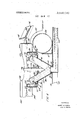
- FIG. 1 is a side elevational view of the specific embodiment of the invention as constructed in accordance with the preferred teaching thereof;
- FIG. 2 is a plan view looking down on the invention and with parts of the invention broken away .to more clearly illustrate some of the features;
- FIG. 3 is a longitudinal, vertical, cross-sectional view of the invention and shows details of construction of the same;
- FIG. 4 on an enlarged scale, is a longitudinal vertical crosssectional view showing details of the construction of the pan and ore concentrator
- FIG. 5, taken on line 5-5 of FIG. 6 (or FIG. 8), is a longitudinal vertical cross-sectional view of another embodiment of the pan and ore concentrator;
- FIG. 6 is a plan view looking down on the pan and ore concentrator similar to that of FIG. 5 but having two tubes instead of four tubes;
- FIG. 7 is an underneath plan view looking up at the invention of FIG. 2;
- FIG. 8 is a plan view looking down on the pan and ore concentrator of FIG. 5 and shows four outlet tubes;
- FIG. 9 is a longitudinal vertical cross-sectional view of another specific embodiment of the invention which is constructed in accordance with the preferred teachings thereof and illustrates an apparatus capable of continuously separating a heavier solid from a lighter solid and a liquid and for collecting the heavier solid;
- FIG. 10, taken on line 10-10 of FIG. 9 is a lateral vertical cross-sectional view looking at the collection box and the rotating separating apparatus;
- FIG. 11, taken on line 11-11 of FIG. 9, is a fragmentary inclined cross-sectional view illustrating the rotating apparatus, the collection box and the chute leading to the collection box;
- FIG. 12, taken on line 12-12 of FIG. 9, is a horizontal, fragmentary cross-sectional view illustrating the rotor and the holes in the rotor slots in the bottom of the pan;
- FIG. [3, taken on line 13-13 of FIG. 9, is a horizontal, fragmentary cross-sectional view of the pan and is looking down on the baffle plate;
- FIG. 14 is an isometric view looking up at a fragmentary portion of the latter part of the pan, the rotor, the baffle plate and the inlet screen;
- FIG. 15 is a vertical lateral cross-sectional view of a water purifier and illustrates the rotor and the cap for directing the purified water away from the rotor;
- FIG. 16, taken on line 16-16 of FIG. 15, is a longitudinal horizontal fragmentary view looking upwardly at the divider between the pan and the housing of said rotor in the water purifier;
- FIG. 17 is a fragmentary plan view looking down on the cap or cover of the water purifier anda portion of the cap broken away to show the part of the rotor 'ofthe water purifier.
- an ore concentrator 10 having a flat frame member 12 and two lateral spaced apart angles 14 and 16.
- the angle 14 is attached to the flat plate member 12 near the rear of 12 and the angle 16 is attached to the flat plate member 12 near the front of the plate member.
- These angles may be attached by means of rivets, bolts, or by welding, or by any convenient standard means for attaching the angle.
- Attached to the rear of the angle 14 and also to the rear part of the member 12 is a cylindrical tube 18.
- Attached to the front of the angle 16 and also to the front of the member 12 is a cylindrical tube 20.
- the cylindrical tubes 18 and 20, and the angles 14 and 16 run laterally across the member 12.
- On each side and on top of the two cylindrical members 20 there is attached a tubular member 22.
- This tubular member runs from the back of the cylindrical member 18, upwardly, then downwardly, and over the front of the cylindrical member 20.
- Attached near the central portion of the tubular members 22 are two spaced apart lateral braces 24 having a depending leg 26 on each side and a flat middle portion.
- the tubular members 22 may be attached to the cylindrical members l8 and 20 by welding and the brace members 24 may be attached to the tubular members 22 by rivets, bolts, and/or welding.
- On each side of 10 there is a longitudinal member having a straight section 28 which overlies the tubular members 22, and has a downwardly depending section 30 which projects forwardly of the cylindrical member 20.
- the straight section 28 may be attached to the legs 26 by means of rivets, bolts, or welding, or other suitable mechanical means.
- a screen 32 Between the two members 30 there is positioned a screen 32. This screen may extend all the way from the lower end of the member 30 to the upper end of the member 30 or substantially where the member 30 meets the member 28. Overlying the upper part of the member 30 and also the screen 32 there is a housing having sides 34 which connect with the member 30 and a flat portion 36. The flat portion 36 covers most of the screen although there is a lower portion of the screen exposed, say the lower fifth of the screen is exposed. In the housing 30 there is a baffle 38 having a handle or grasping portion 40. The bafile 38 is positioned between the sides 34 and positioned above the flat member 36. On the lower.
- a housing having depending legs 42, a front portion 44, a rear portion 46, and a bottom 48.
- This housing extends from the outer part of the member 30, underneath theexposed portion of the screen 32 and to the other member 30. It acts as a basin or a trap for ore and liquid which is passed through the exposed portion of the screen 32.
- In the rear wall 46 there is an opening 50.
- a pipe 52 having an inlet 54 near the front wall 44. The pipe 52 runs rearwardly from the inlet 54 and approximately near the middle of the concentrator 10 the pipe 52 bends upwardly into a short pipe 56.
- the pipe 52 is approximately on the longitudinal centerline of the concentrator l0 and is in between the downwardly depending spaced apart legs 58 of channel member 59. These legs 58 run longitudinally along the inner part of the concentrator 10.
- a collar 60 surrounds the short tube or pipe 56 and is on the upper part of the flat member 12. This collar 60 positions the short member 56. Actually, the collar 60 may be considered to be internally tapped and the outer portion of the pipe 56 may be threaded so that the collar 60 is screwed onto the pipe 56 so as to press the of approximately 56 to 60. From experience, I have found a desirable angle to be about 58. At the lower part of the two tubes 64 and 66 there is an opening 68.
- This opening surrounds the top of the tube 56 and may be approximately an eighth of an inch to three-eighths of an inch below the top of the tube 56 so as to just circumscribe the upper part of the tube 56.
- the top of the tube 64 is sealed at 70 and the top of the tube 66 is sealed at 72.
- the openings 74 and 76 are on the trailing faces of the tubes 64 and 66 so that liquid and solids flow out of the openings 74 and 76 as the two tubes 64 and 66 rotate.
- the clearance between the inner edge of the tubes 64 and 66 of the openings 68 and the outer surface of the tube 56 should be in the range of approximately one-sixteenth of an inch to three-sixteenths of an inch.
- the tubes 64 and 66 are partially in a pair 78.
- This pan comprises circular sides 80 having an upper lip 82.
- the lower part of the sides 88 curve inwardly at 84 and form a flat portion 86.
- the flat portion 86 curves downwardly and inwardly to form member 88.
- the member 88 is in the configuration of a frustum of a cone and terminates at approximately the same place as the lower part of the two tubes 6 1 and 66 or near the opening 68 of these two tubes 64 and 66.
- a circular member having a curved cuplike portion 96.
- the inner part of this cuplike portion 96 depends downwardly at 92 and then inwardly at 94.
- the flat portion 94 contacts the legs 64 and 66 so as to seal the opening between the member 88 and the legs 64 and 66 on the bottom of the pan 78.
- the central portion of the pan 78 is flat and has an opening at 96.
- a center boss 98 is positioned above the center of the pan 78 and has a passageway 100 which is aligned with the passageway 96.
- the center boss 98 has a circular base 102 which has an opening 104 to receive the upper part of the leg 64 and has an opening 106 to receive the upper part of the leg 66.
- a shaft 108 In the passageway 100 and the opening 96 there is positioned a shaft 108.
- a rubber ring or a plastic ring 1111 In the upper part of the pan 78 and inside of the pan and below the curved upper lip 82 there is positioned a rubber ring or a plastic ring 1111. This ring 110 functions as a barrier to prevent the flow of solids out of the pan 78.
- pan 78, the tubes 64, 66, and the shaft 98 are united into a unitary or integral structure. With the rotation of the shaft 108 the pan 78 and the tubes 64 and 66 rotate. As there is a clearance between the lower ends of the tubes 64 and 66 and the tube 56 it is seen that with the rotation of 78, 64 and 66 that there is no rotation of the tube 56.
- a housing 120 On the upper part of the lateral braces 24 there is positioned a housing 120.
- This housing 120 has a hollow interior 122.
- the housing may be attached to the cross braces 24 by welding or riveting or any suitable mechanical means.
- the front part of the housing 120 is positioned above the shaft 108.
- a bearing 124 and a bearing 126 In fact, in the housing 120 there is a bearing 124 and a bearing 126.
- the upper part of the shaft 108 is in the housing 120 and is journaled in the two bearings 124i and 126.
- On the rear part of the housing 120 there is positioned a motor 130.
- the motor 130 has a depending output shaft 132.
- a sprocket 134 On the output shaft 132 there is a sprocket 134. A chain 136 runs between the sprocket 134 and the sprocket 128 so that the output shaft 132 drives the shaft 108.
- a stand 138 On the upper part of the housing 120 there is attached a stand 138. The stand 138 may be attached to the housing 120 by means of rivets or bolts and the like. Attached to the stand 138 is a handle 140 for ease of carrying the ore concentrator 10.
- the housing Around the upper portion of the pan 78 and the lower portion of the shaft 108 there is a case or housing having an upper flat member 142, a lower flat member 1:14, a front wall 146, and sidewalls 168. It is seen that there is no rear wall or that there is an opening 150. In fact, from FIGS. 3 and 4 it is seen that the housing is composed of an upper portion and a lower portion which may be joined at the lip 152.
- the members 144, M2, 146, 148 may be composed of plastic such as polystyrene or reinforced fiber glass.
- this band extends from below the upper part of the pan 78 and also above the upper part of the pan 78.
- This high impact resistance polystyrene band reduces abrasion on the walls 148 and 146.
- the band 154 prevents abrasion of the walls 146 and 148 and itself is abraded only to a very small degree. After considerable usage the band 154 showed substantially no abra- In the cylindrical tubes 18 and 20 there is positioned an inflatable bag 156.
- the bag 156 may be of a long tubular construction and can be inflated at the site of usage. The reason for this is that the ore concentrator floats on water. In use, I have placed the ore concentrator in a stream or partially on the bank of a stream and partially in water. Then, I have shoveled sand and dirt and the like from the stream bed onto the platelike member 36 so that it runs down onto the screen 32. When the ore concentrator 10 is not being used then the floats 156 may be deflated and the ore concentrator carried to the next site of usage or stored.
- FIGS. 5 and 6 there is illustrated another version of the rotating part of the concentrator.
- This version 160 comprises a pan having circular sides 162 and an upwardly and inwardly curving lip 166. Also, the sides 162 curve downwardlyand inwardly at 166 and into the bottom 168 of the pan.
- the pan 168 there project two tubes 170 and 172. Tube 170 projects through an opening'l74 and the tube 172 projects through an opening 176. In fact, these two tubes may be welded into position in the bottom 168. The upper part of the tube 170 is enclosed in 178 and the upper part of the tube 162 is enclosed in 180.
- the lower part of the tubes 170 and 172 meet in a tubular member 182. As is seen in FIG. 5 the upper part of the tubes 170 and 172 unite while the lower part of these tubes form an opening and depend into a tubular member 182. Inside of the leg 170 there is another leg 186 and inside of the leg 172 there is a leg 188. The outer surface of theleg 186 is spaced approximately an eighth of an inch from the inner surface of the leg 170 and the outer surface of the leg 188 is spaced approximately an eighth of an inch from the inner surface of the leg 172. The leg 186 is approximately half the length of the leg 170 and the leg 188 is approximately half the length of the leg 172.
- the legs 186 and 188 join at their inner upper portion and depend downwardly to form an opening.
- the lower end of the legs 186 and 188 form a tubular member 190.
- the tubular member 190 extends below the lower end of the tubular member 182.
- the member 192 with opening 194 is the equivalent of an orifice.
- the tubes 186 and 188 are open at the top and are spaced inside the tubes 170 and 172 by, means of spacers 196. i
- the lower end of the tube 190 surrounds the top of the tube 56.
- the distance between the inner surface of the tube 190 and the outer surface of the tube 56 should be in the range of approximately one-sixteenth of an inch to three-sixteenths of an inch or a clearance of thatdistance.
- the lower part of the tube 1182 need not surround the upper part of the tube 56.
- the angle between the two tubes 170 and 172, and the angle between the two tubes 186 and 188 may be in the range of approximately 56 to 60. From experience, I have found that an angle of 58 is desirable.
Abstract
This invention is a centrifugal ore concentrating vessel mounted for rotation about an axis and provided with the plurality of feed means which extend through the base of the vessel and are rotatable with the rotation of the vessel. The feed means define a common feed inlet opening below the base and plural discharge openings within the vessel. Further, this centrifugal ore concentrating vessel may be used to separate solids from liquids so as to purify the liquid.
Description
United States Patent [72] Inventors Harry E. Smith 101 14-115th Avenue S.E.; Leo A. Smith, 2216 Dayton Avenue N .E., Renton, Wash. 98055 [21] Appl. No. 777,938 [22] Filed Sept. 26, 1968 [45] Patented Jan. 26, 1971 Continuation-impart of application Ser. No. 407,629, Oct. 30, 1964, now abandoned.
[54] ORE CONCENTRATOR 7 Claims, 17 Drawing Figs.
[52] U.S.Cl 233/21, 209/44: 233/1, 233/2, 233/28, 233/45 [51] Int. Cl B04b 11/00, [50] Field of Search 209/44, 211, 453, 465, 497, 444, 183; 233/27, 28, 45, 21, 1, 2, 3; 210/242, 360A, 320
[56] References Cited UNITED STATES PATENTS 539,239 5/1895 Smith 233/27 603,794 5/1898 Perks 233/14 Primary Examiner-Frank W. Lutter Assistant ExaminerWilli'am L. Mentlik Att0rneyThomas W. Secrest ABSTRACT: This invention is a centrifugal ore concentrating vessel mounted for rotation about an axis and provided with the plurality of feed means which extend through the base of the vessel and are rotatable with the rotation of the vessel. The feed means define a common feed inlet opening below the base and plural discharge openings within the vessel. Further, this centrifugal ore concentrating vessel may be used to separate solids from liquids so as to purify the liquid.
PATENIED mes WI SHEET 01g;
fi V fix q Q E NM h N ME u$$= l m. M n A. M I n o WWOM m H Q QR $3 3 INVENTORS HARRY E. SMITH LEO A. SMITH PATENTEUJms l9?! SHEET 03 0F 17 INVENTORS HARRY E. SMITH LEO A. SMITH Pmmmmsm SHEET [W [1F lNVENTORS HARRY E SMITH LEO A. SMITH PATENTEH JAN 2 6 WI SHEET 05 0F INVENTORS HARRY E. SMITH LEO A. SMITH PATENTEI] m2 619?:
sum p5 or INVENTOR.
A 1 1/12 S'ecresf memo was an SHEET 09 [If INVENTOR. 5 fmzi' PATENTEUJANZSIBYI $558,043
SHEET 11 HF 17 I NVENTOR. 44/91: .imr
PATENTEnJAuzslsn 3558,0413
' sum 12 nr 17 F/G. l2
INVENTOR.
BY Ze 4.
PATENTED JANZS |97| 3 558.043 SHEET 13 0F 17 FIG. /3
INVENTOR.
7 rad PATENTEDJANZSIH?! 355 ,04
sum 1a or 17 f IAVENTOR.
Wferresi' one CONCENTRATOR This invention is for a concentrator to concentrate ore so as to recover valuable elements and compounds, and is a continuation-in-part of our previously filed patent application entitled ORE CONCENTRATOR, filing date of Oct. 30, I964, Ser. No. 407,629 now abandoned.
One of the objects of this invention is to provide an efficient apparatus for concentrating ore; to provide an apparatus which is light in weight, small in volume, and may be transported by one man; to provide such an apparatus having relatively few moving parts and which may easily be maintained in operating condition; and, to provide such an apparatus which is inexpensive to manufacture.
Further, important objects of this invention are to provide an apparatus for continuously separating the heavier solid from the lighter solid and liquid; to provide such an apparatus having a means for collecting the heavier solid so as to easily and quickly remove the heavier solid from the apparatus; and, to provide an apparatus which is capable of separating a liquid from a solid on a continuous basis so as to purify the liquid from the solid.
These and other important objects and advantages of the invention will be more particularly brought forth upon reference to the detailed specification of the invention, the claims in the application, and the accompanying drawings.
In the drawings:
FIG. 1 is a side elevational view of the specific embodiment of the invention as constructed in accordance with the preferred teaching thereof;
FIG. 2 is a plan view looking down on the invention and with parts of the invention broken away .to more clearly illustrate some of the features;
FIG. 3 is a longitudinal, vertical, cross-sectional view of the invention and shows details of construction of the same;
FIG. 4, on an enlarged scale, is a longitudinal vertical crosssectional view showing details of the construction of the pan and ore concentrator;
FIG. 5, taken on line 5-5 of FIG. 6 (or FIG. 8), is a longitudinal vertical cross-sectional view of another embodiment of the pan and ore concentrator;
FIG. 6 is a plan view looking down on the pan and ore concentrator similar to that of FIG. 5 but having two tubes instead of four tubes;
FIG. 7 is an underneath plan view looking up at the invention of FIG. 2;
FIG. 8 is a plan view looking down on the pan and ore concentrator of FIG. 5 and shows four outlet tubes;
FIG. 9 is a longitudinal vertical cross-sectional view of another specific embodiment of the invention which is constructed in accordance with the preferred teachings thereof and illustrates an apparatus capable of continuously separating a heavier solid from a lighter solid and a liquid and for collecting the heavier solid;
FIG. 10, taken on line 10-10 of FIG. 9 is a lateral vertical cross-sectional view looking at the collection box and the rotating separating apparatus;
FIG. 11, taken on line 11-11 of FIG. 9, is a fragmentary inclined cross-sectional view illustrating the rotating apparatus, the collection box and the chute leading to the collection box;
FIG. 12, taken on line 12-12 of FIG. 9, is a horizontal, fragmentary cross-sectional view illustrating the rotor and the holes in the rotor slots in the bottom of the pan;
FIG. [3, taken on line 13-13 of FIG. 9, is a horizontal, fragmentary cross-sectional view of the pan and is looking down on the baffle plate;
FIG. 14, is an isometric view looking up at a fragmentary portion of the latter part of the pan, the rotor, the baffle plate and the inlet screen;
FIG. 15 is a vertical lateral cross-sectional view of a water purifier and illustrates the rotor and the cap for directing the purified water away from the rotor;
FIG. 16, taken on line 16-16 of FIG. 15, is a longitudinal horizontal fragmentary view looking upwardly at the divider between the pan and the housing of said rotor in the water purifier; and
FIG. 17 is a fragmentary plan view looking down on the cap or cover of the water purifier anda portion of the cap broken away to show the part of the rotor 'ofthe water purifier.
In the drawings it is seen that there is an ore concentrator 10 having a flat frame member 12 and two lateral spaced apart angles 14 and 16. The angle 14 is attached to the flat plate member 12 near the rear of 12 and the angle 16 is attached to the flat plate member 12 near the front of the plate member. These angles may be attached by means of rivets, bolts, or by welding, or by any convenient standard means for attaching the angle. Attached to the rear of the angle 14 and also to the rear part of the member 12 is a cylindrical tube 18. Attached to the front of the angle 16 and also to the front of the member 12 is a cylindrical tube 20. The cylindrical tubes 18 and 20, and the angles 14 and 16 run laterally across the member 12. On each side and on top of the two cylindrical members 20 there is attached a tubular member 22. This tubular member runs from the back of the cylindrical member 18, upwardly, then downwardly, and over the front of the cylindrical member 20. Attached near the central portion of the tubular members 22 are two spaced apart lateral braces 24 having a depending leg 26 on each side and a flat middle portion. The tubular members 22 may be attached to the cylindrical members l8 and 20 by welding and the brace members 24 may be attached to the tubular members 22 by rivets, bolts, and/or welding. On each side of 10 there is a longitudinal member having a straight section 28 which overlies the tubular members 22, and has a downwardly depending section 30 which projects forwardly of the cylindrical member 20. The straight section 28 may be attached to the legs 26 by means of rivets, bolts, or welding, or other suitable mechanical means. Between the two members 30 there is positioned a screen 32. This screen may extend all the way from the lower end of the member 30 to the upper end of the member 30 or substantially where the member 30 meets the member 28. Overlying the upper part of the member 30 and also the screen 32 there is a housing having sides 34 which connect with the member 30 and a flat portion 36. The flat portion 36 covers most of the screen although there is a lower portion of the screen exposed, say the lower fifth of the screen is exposed. In the housing 30 there is a baffle 38 having a handle or grasping portion 40. The bafile 38 is positioned between the sides 34 and positioned above the flat member 36. On the lower. part of the members 30 there is a housing having depending legs 42, a front portion 44, a rear portion 46, and a bottom 48. This housing extends from the outer part of the member 30, underneath theexposed portion of the screen 32 and to the other member 30. It acts as a basin or a trap for ore and liquid which is passed through the exposed portion of the screen 32. In the rear wall 46 there is an opening 50. In the opening 50 there is positioned a pipe 52 having an inlet 54 near the front wall 44. The pipe 52 runs rearwardly from the inlet 54 and approximately near the middle of the concentrator 10 the pipe 52 bends upwardly into a short pipe 56. The pipe 52 is approximately on the longitudinal centerline of the concentrator l0 and is in between the downwardly depending spaced apart legs 58 of channel member 59. These legs 58 run longitudinally along the inner part of the concentrator 10. A collar 60 surrounds the short tube or pipe 56 and is on the upper part of the flat member 12. This collar 60 positions the short member 56. Actually, the collar 60 may be considered to be internally tapped and the outer portion of the pipe 56 may be threaded so that the collar 60 is screwed onto the pipe 56 so as to press the of approximately 56 to 60. From experience, I have found a desirable angle to be about 58. At the lower part of the two tubes 64 and 66 there is an opening 68. This opening surrounds the top of the tube 56 and may be approximately an eighth of an inch to three-eighths of an inch below the top of the tube 56 so as to just circumscribe the upper part of the tube 56. The top of the tube 64 is sealed at 70 and the top of the tube 66 is sealed at 72. In the tube 66, and on that portion away from the tube 66, there is an opening 76. Also, in the tube 66, and on that face away from the tube 641 there is an opening 76. The openings 74 and 76 are on the trailing faces of the tubes 64 and 66 so that liquid and solids flow out of the openings 74 and 76 as the two tubes 64 and 66 rotate.
From experience we have found that the clearance between the inner edge of the tubes 64 and 66 of the openings 68 and the outer surface of the tube 56 should be in the range of approximately one-sixteenth of an inch to three-sixteenths of an inch.
The tubes 64 and 66 are partially in a pair 78. This pan comprises circular sides 80 having an upper lip 82. The lower part of the sides 88 curve inwardly at 84 and form a flat portion 86. The flat portion 86 curves downwardly and inwardly to form member 88. The member 88 is in the configuration of a frustum of a cone and terminates at approximately the same place as the lower part of the two tubes 6 1 and 66 or near the opening 68 of these two tubes 64 and 66.
In the lower part of the pan 78 there is a circular member having a curved cuplike portion 96. The inner part of this cuplike portion 96 depends downwardly at 92 and then inwardly at 94. The flat portion 94 contacts the legs 64 and 66 so as to seal the opening between the member 88 and the legs 64 and 66 on the bottom of the pan 78. Further, the central portion of the pan 78 is flat and has an opening at 96. A center boss 98 is positioned above the center of the pan 78 and has a passageway 100 which is aligned with the passageway 96. The center boss 98 has a circular base 102 which has an opening 104 to receive the upper part of the leg 64 and has an opening 106 to receive the upper part of the leg 66. In the passageway 100 and the opening 96 there is positioned a shaft 108.
In the upper part of the pan 78 and inside of the pan and below the curved upper lip 82 there is positioned a rubber ring or a plastic ring 1111. This ring 110 functions as a barrier to prevent the flow of solids out of the pan 78.
It is seen that the pan 78, the tubes 64, 66, and the shaft 98 are united into a unitary or integral structure. With the rotation of the shaft 108 the pan 78 and the tubes 64 and 66 rotate. As there is a clearance between the lower ends of the tubes 64 and 66 and the tube 56 it is seen that with the rotation of 78, 64 and 66 that there is no rotation of the tube 56.
On the upper part of the lateral braces 24 there is positioned a housing 120. This housing 120 has a hollow interior 122. The housing may be attached to the cross braces 24 by welding or riveting or any suitable mechanical means. As is seen, the front part of the housing 120 is positioned above the shaft 108. In fact, in the housing 120 there is a bearing 124 and a bearing 126. The upper part of the shaft 108 is in the housing 120 and is journaled in the two bearings 124i and 126. On the shaft 108, and between the bearings 124 and 126, there is positioned a sprocket 128. On the rear part of the housing 120 there is positioned a motor 130. The motor 130 has a depending output shaft 132. On the output shaft 132 there is a sprocket 134. A chain 136 runs between the sprocket 134 and the sprocket 128 so that the output shaft 132 drives the shaft 108. On the upper part of the housing 120 there is attached a stand 138. The stand 138 may be attached to the housing 120 by means of rivets or bolts and the like. Attached to the stand 138 is a handle 140 for ease of carrying the ore concentrator 10.
Around the upper portion of the pan 78 and the lower portion of the shaft 108 there is a case or housing having an upper flat member 142, a lower flat member 1:14, a front wall 146, and sidewalls 168. It is seen that there is no rear wall or that there is an opening 150. In fact, from FIGS. 3 and 4 it is seen that the housing is composed of an upper portion and a lower portion which may be joined at the lip 152. The members 144, M2, 146, 148 may be composed of plastic such as polystyrene or reinforced fiber glass. On the inside of the walls 148 and 146 there is attached a protective band of high impact resistance polystyrene 15:1. In FIG. 4 it is seen that this band extends from below the upper part of the pan 78 and also above the upper part of the pan 78. This high impact resistance polystyrene band reduces abrasion on the walls 148 and 146. As can be readily visualized, ore and solids are thrown out of the pan and strike the band 154. If this band were not present, the walls 148 and 146 would be abraded and in time holes would be worn in these walls. From experience we have found that the band 154 prevents abrasion of the walls 146 and 148 and itself is abraded only to a very small degree. After considerable usage the band 154 showed substantially no abra- In the cylindrical tubes 18 and 20 there is positioned an inflatable bag 156. The bag 156 may be of a long tubular construction and can be inflated at the site of usage. The reason for this is that the ore concentrator floats on water. In use, I have placed the ore concentrator in a stream or partially on the bank of a stream and partially in water. Then, I have shoveled sand and dirt and the like from the stream bed onto the platelike member 36 so that it runs down onto the screen 32. When the ore concentrator 10 is not being used then the floats 156 may be deflated and the ore concentrator carried to the next site of usage or stored.
In FIGS. 5 and 6 there is illustrated another version of the rotating part of the concentrator. This version 160 comprises a pan having circular sides 162 and an upwardly and inwardly curving lip 166. Also, the sides 162 curve downwardlyand inwardly at 166 and into the bottom 168 of the pan. In the pan 168 there project two tubes 170 and 172. Tube 170 projects through an opening'l74 and the tube 172 projects through an opening 176. In fact, these two tubes may be welded into position in the bottom 168. The upper part of the tube 170 is enclosed in 178 and the upper part of the tube 162 is enclosed in 180.
The lower part of the tubes 170 and 172 meet in a tubular member 182. As is seen in FIG. 5 the upper part of the tubes 170 and 172 unite while the lower part of these tubes form an opening and depend into a tubular member 182. Inside of the leg 170 there is another leg 186 and inside of the leg 172 there is a leg 188. The outer surface of theleg 186 is spaced approximately an eighth of an inch from the inner surface of the leg 170 and the outer surface of the leg 188 is spaced approximately an eighth of an inch from the inner surface of the leg 172. The leg 186 is approximately half the length of the leg 170 and the leg 188 is approximately half the length of the leg 172. The legs 186 and 188 join at their inner upper portion and depend downwardly to form an opening. The lower end of the legs 186 and 188 form a tubular member 190. The tubular member 190 extends below the lower end of the tubular member 182. In approximately the middle of the tubular member 191] there is a circular crossmember 192 having an opening 194 therein. The member 192 with opening 194 is the equivalent of an orifice. The tubes 186 and 188 are open at the top and are spaced inside the tubes 170 and 172 by, means of spacers 196. i
The lower end of the tube 190 surrounds the top of the tube 56. In fact, the distance between the inner surface of the tube 190 and the outer surface of the tube 56 should be in the range of approximately one-sixteenth of an inch to three-sixteenths of an inch or a clearance of thatdistance. The lower part of the tube 1182 need not surround the upper part of the tube 56.
The angle between the two tubes 170 and 172, and the angle between the two tubes 186 and 188 may be in the range of approximately 56 to 60. From experience, I have found that an angle of 58 is desirable.
In the upper part of the tube 170 and in the upper part of the tube 172 there are openings 2011. These openings Zilllare in the trailing portions of these tubes as these tubes rotate.
Claims (7)
1. An ore concentrator, said concentrator comprising: a. a pan having a base, a side and an inwardly directed lip on the side; b. there being at least two tubes; c. each of said tubes being on both sides of the base of said pan and terminating inside of said pan; d. the end of each tube in the pan being sealed; e. each tube having a first opening inside of the pan; f. said tubes being at an angle with each other; g. the outer end of each tube outside said pan joining together to form a unitary structure having a second opening; h. a third tube and a fourth tube; i. said third tube being in one of said tubes and the fourth tube being in the other one of said tubes; j. said third and fourth tubes being at an angle with respect to each other; k. the outer end of the third and fourth tubes joining together to form a unitary structure having a third opening; l. a pipe leading into said third opening; m. there being a clearance between said third opening and the pipe; and n. a means to rotate the pan and the tubes.
2. A purifier for separating a liquid from a solid, said purifier comprising: a. a rotor having a housing, a pan and a divider; b. said housing and said pan connecting with each other; c. said divider separating said housing and said pan; d. there being a first means in said divider to allow communication between the housing and the pan; e. said pan having openings to allow solids and liquids to leave said pan; f. said housing having an open end for connecting with a source of a mixture of liquid and solid; g. a first baffle in said pan; h. said first baffle being positioned away from said divider and said housing; i. a third means to direct said liquid from said pan; and j. a fourth means to rotate said rotor including the housing, the pan and the divider.
3. A purifier according to claim 2 and comprising: a. a fifth means to divide said housing into a plurality of compartments; b. said compartments and said pan communicating by said first means; and c. said housing being in the configuration of a frustum of a cone with the small part of the cone having said open end.
4. A purifier according to claim 2 and comprising: a. said pan having a bottom wall wHich extends radially outwardly beyond the top edge of the housing; b. said pan having a passageway in that part of the bottom wall and said passageway juxtapositioned to the peripheral portion of said bottom wall; and c. said passageway allowing solid and liquid to leave the pan.
5. A purifier according to claim 4 and comprising: a. a rotating second baffle in said pan; b. said rotating second baffle being positioned adjacent but spaced apart from said divider; and c. said rotating second baffle overlies said first baffle for directing solid and liquid toward said bottom wall.
6. A purifier according to claim 4 and comprising: a. a plurality of said rotating second baffles in said pan.
7. A purifier according to claim 4 and comprising: a. a fifth means to float said purifier on a mixture of the liquid and solid; and b. said fifth means permitting the open end of said housing to be in said mixture of the liquid and solid.
Applications Claiming Priority (1)
| Application Number | Priority Date | Filing Date | Title |
|---|---|---|---|
| US77793868A | 1968-09-26 | 1968-09-26 |
Publications (1)
| Publication Number | Publication Date |
|---|---|
| US3558043A true US3558043A (en) | 1971-01-26 |
Family
ID=25111768
Family Applications (1)
| Application Number | Title | Priority Date | Filing Date |
|---|---|---|---|
| US777938A Expired - Lifetime US3558043A (en) | 1968-09-26 | 1968-09-26 | Ore concentrator |
Country Status (1)
| Country | Link |
|---|---|
| US (1) | US3558043A (en) |
Cited By (4)
| Publication number | Priority date | Publication date | Assignee | Title |
|---|---|---|---|---|
| US3950246A (en) * | 1974-10-25 | 1976-04-13 | Klefisch Dieter G A | Dredge units |
| US4347861A (en) * | 1981-02-25 | 1982-09-07 | Whirlpool Corporation | Dishwasher soil separator |
| US20080197689A1 (en) * | 2007-02-15 | 2008-08-21 | Brian Rothery | Non-motorized gold mining apparatus |
| US20100019562A1 (en) * | 2007-02-15 | 2010-01-28 | Brian Rothery | Non-Motorized Gold Mining Apparatus |
Citations (11)
| Publication number | Priority date | Publication date | Assignee | Title |
|---|---|---|---|---|
| US539239A (en) * | 1895-05-14 | Centrifugal water-lift | ||
| US603794A (en) * | 1898-05-10 | Gold-separating machine | ||
| US617466A (en) * | 1899-01-10 | Apparatus for separating precious metals from their ores | ||
| US665835A (en) * | 1900-10-13 | 1901-01-08 | James M Miller | Sand-washing apparatus. |
| US791496A (en) * | 1904-08-15 | 1905-06-06 | Anders Ponten | Centrifugal cream-separator. |
| US882030A (en) * | 1908-03-17 | Paul Traulsen | Filter. | |
| US980001A (en) * | 1906-09-27 | 1910-12-27 | James D Millar | Centrifugal sluicing-machine. |
| US2084487A (en) * | 1935-05-11 | 1937-06-22 | Haraldson Olaf | Method and means for recovering gold |
| US2256504A (en) * | 1938-05-23 | 1941-09-23 | Frank P Stewart | Gold concentrator |
| US2858064A (en) * | 1954-12-21 | 1958-10-28 | Raymond W Clow | Mineral separator |
| US2881974A (en) * | 1955-08-08 | 1959-04-14 | Ruf Walter | Centrifuge |
-
1968
- 1968-09-26 US US777938A patent/US3558043A/en not_active Expired - Lifetime
Patent Citations (11)
| Publication number | Priority date | Publication date | Assignee | Title |
|---|---|---|---|---|
| US539239A (en) * | 1895-05-14 | Centrifugal water-lift | ||
| US603794A (en) * | 1898-05-10 | Gold-separating machine | ||
| US617466A (en) * | 1899-01-10 | Apparatus for separating precious metals from their ores | ||
| US882030A (en) * | 1908-03-17 | Paul Traulsen | Filter. | |
| US665835A (en) * | 1900-10-13 | 1901-01-08 | James M Miller | Sand-washing apparatus. |
| US791496A (en) * | 1904-08-15 | 1905-06-06 | Anders Ponten | Centrifugal cream-separator. |
| US980001A (en) * | 1906-09-27 | 1910-12-27 | James D Millar | Centrifugal sluicing-machine. |
| US2084487A (en) * | 1935-05-11 | 1937-06-22 | Haraldson Olaf | Method and means for recovering gold |
| US2256504A (en) * | 1938-05-23 | 1941-09-23 | Frank P Stewart | Gold concentrator |
| US2858064A (en) * | 1954-12-21 | 1958-10-28 | Raymond W Clow | Mineral separator |
| US2881974A (en) * | 1955-08-08 | 1959-04-14 | Ruf Walter | Centrifuge |
Cited By (6)
| Publication number | Priority date | Publication date | Assignee | Title |
|---|---|---|---|---|
| US3950246A (en) * | 1974-10-25 | 1976-04-13 | Klefisch Dieter G A | Dredge units |
| US4347861A (en) * | 1981-02-25 | 1982-09-07 | Whirlpool Corporation | Dishwasher soil separator |
| US20080197689A1 (en) * | 2007-02-15 | 2008-08-21 | Brian Rothery | Non-motorized gold mining apparatus |
| US7597401B2 (en) * | 2007-02-15 | 2009-10-06 | Brian Rothery | Non-motorized gold mining apparatus |
| US20100019562A1 (en) * | 2007-02-15 | 2010-01-28 | Brian Rothery | Non-Motorized Gold Mining Apparatus |
| US8240775B2 (en) | 2007-02-15 | 2012-08-14 | Brian Rothery | Non-motorized gold mining apparatus |
Similar Documents
| Publication | Publication Date | Title |
|---|---|---|
| US4072481A (en) | Device for separating multiple phase fluid systems according to the relative specific gravities of the phase | |
| US4184967A (en) | Apparatus for clarifying waste water | |
| US3558043A (en) | Ore concentrator | |
| US4332350A (en) | Centrifuge apparatus for separating entrained solids from industrial waste water | |
| US2418061A (en) | Centrifugal air separator and screening device for comminuted material | |
| US2584976A (en) | Apparatus for concentrating ores and the like | |
| US4451371A (en) | Apparatus for separating liquid from a slurry | |
| FR2369175A1 (en) | SIDE WALL FOR CONTAINERS INTENDED FOR TRANSPORT | |
| GB1484496A (en) | Apparatus for continuously separating debris from beets or other roots or tubers | |
| US3910837A (en) | Portable placer mining apparatus | |
| US5033332A (en) | Method and apparatus for concentrating transition elements from particulate sources | |
| US5043059A (en) | Concentrator for beneficiating minerals | |
| US3368278A (en) | Machine for separating curd and whey | |
| US837705A (en) | Separator. | |
| US4517079A (en) | Ore separation system | |
| GB1025610A (en) | Thickening and/or classifying apparatus | |
| US5476177A (en) | Sluice trap | |
| US3168466A (en) | Separator for metals in liquid suspension | |
| US2756977A (en) | Device for recovering gold from streams | |
| ES8302481A1 (en) | Apparatus for the separation of relatively heavy foreign bodies from less heavy bodies, conveyed in a liquid stream | |
| US5366092A (en) | Separation of valuable minerals from material found in the beds of bodies of water | |
| RU95117778A (en) | MOBILE CONCENTRATING UNIT WITH CONTINUOUS CONCENTRATE OUTPUT | |
| US2110654A (en) | Separator | |
| US4637872A (en) | Gravel washer separator | |
| US972463A (en) | Ore-concentrator. |