US35549A - Improvement in coal-oil lamps - Google Patents
Improvement in coal-oil lamps Download PDFInfo
- Publication number
- US35549A US35549A US35549DA US35549A US 35549 A US35549 A US 35549A US 35549D A US35549D A US 35549DA US 35549 A US35549 A US 35549A
- Authority
- US
- United States
- Prior art keywords
- oil
- burner
- retort
- piece
- lamp
- Prior art date
- Legal status (The legal status is an assumption and is not a legal conclusion. Google has not performed a legal analysis and makes no representation as to the accuracy of the status listed.)
- Expired - Lifetime
Links
- 239000010742 number 1 fuel oil Substances 0.000 title description 10
- 239000003921 oil Substances 0.000 description 64
- 238000002485 combustion reaction Methods 0.000 description 16
- 239000007788 liquid Substances 0.000 description 10
- 239000000203 mixture Substances 0.000 description 8
- 235000019645 odor Nutrition 0.000 description 8
- 230000000694 effects Effects 0.000 description 6
- 239000007789 gas Substances 0.000 description 6
- 230000000875 corresponding Effects 0.000 description 4
- 238000004880 explosion Methods 0.000 description 4
- 239000004215 Carbon black (E152) Substances 0.000 description 2
- 240000002444 Sphenoclea zeylanica Species 0.000 description 2
- 230000001154 acute Effects 0.000 description 2
- 238000005452 bending Methods 0.000 description 2
- 230000001276 controlling effect Effects 0.000 description 2
- 239000010779 crude oil Substances 0.000 description 2
- 230000002708 enhancing Effects 0.000 description 2
- 238000001704 evaporation Methods 0.000 description 2
- 239000003517 fume Substances 0.000 description 2
- 150000002430 hydrocarbons Chemical class 0.000 description 2
- 239000004615 ingredient Substances 0.000 description 2
- 230000001788 irregular Effects 0.000 description 2
- 239000000463 material Substances 0.000 description 2
- 230000001105 regulatory Effects 0.000 description 2
- 230000000284 resting Effects 0.000 description 2
- 239000000341 volatile oil Substances 0.000 description 2
Images


Classifications
-
- F—MECHANICAL ENGINEERING; LIGHTING; HEATING; WEAPONS; BLASTING
- F23—COMBUSTION APPARATUS; COMBUSTION PROCESSES
- F23D—BURNERS
- F23D11/00—Burners using a direct spraying action of liquid droplets or vaporised liquid into the combustion space
- F23D11/36—Details, e.g. burner cooling means, noise reduction means
- F23D11/44—Preheating devices; Vaporising devices
Definitions
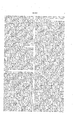
- Figure 1 is a side elevation of my improved lamp; Fig. 2, a central vertical section thereof; Fig. 3, a plan of the under side of a part detached; Fig. 4, a horizontal section, looking upward, in a plane indicated by the line a a, Fig. 2; Figs. 5 and 6, bottom views of parts detached; Fig. 7, a side View of a part detached.
- My invention consists in certain improvements in lamps,by which I am enabled to burn coal-oil and other oils of similar properties without danger of explosions, without the use of chimneys, and yet by which I control the draft so as to effect perfect combustion of the oil and produce apure and brilliant light, and by which crude oil4 may be burned without any offensive odors arising therefrom.
- the lamp-body or oil-reservoir A, stem B, and base C are made of suitable material, and
- ⁇ may be all cast in one piece.
- a disk, J (a bottom view of which is shown in Fig. 3,) is made of less than the interior diameter of the oilreservoir. From the center of this disk a rod, H, extends downward into the hollow stem B of the lamp and terminates with a nut or head, E, which fits so as to slide up and down in the stem. A coiled spring,D,in the bottom ofthe lamp-stem presses upward against the head E, whereby the continual upward pressure of the liftingcup is produced.
- Vertical slots b b are made in the sides of the stem B, through which projections e e from the head E extend outward. These serve to limit the extent to which the lifting-cup may be pressed upward, and these projections terminate in Ysuitable knobs, by Which the lifting-cup may be drawn downward again into the betteln of the oil-reservoir for refilling the lamp. Side notches, c c, are made at the bottoms of the slots b b, into which the projections e e are turned to hold down the lifting-cup while the lamp is filling; or any equivalent means may be employed for the purpose.
- the liftingcup is made flexible, both sides and bottom, and is suitably secured upon the top of the disk J, near the periphery thereof,
- an elastic band or ring, O lits inside of the same, and has its upper edgeserrated, so as to form a number of points, o 0,' which, by their separate elasticity, press the upper edge of the cup all around closely in contact with the interior surface of the reser- êt, Whether smooth or irregular, and at the i same time support the said upper edge of the cup from bending and lopping inward out of place and shape.
- the lower edge of the side of the cup does not come in contact withthe oil-reservoir; but in case any oil should get below the lifting-cup provision is made for forcing it back above it again by having a hole or holes, Z, in the middle of the cup-bottom and a number ⁇ of apertures, J J, not .opposite to the hole or holes Z, through the disk J; and since the middle of the cup-bottom liesloose upon the disk when the cup is drawn do wn into the betteln of the oil-reservoir, the pressure upon the oil below causes it to ascend through the apertures j j and to raise the middle of the cup-bottom a little from the disk, and thus find a passageto and through the hole or holes Z.
- a suitable packing, I should surround the rod H, to prevent any oil from leaking down into the base of the lamp; and this, in connection with the head E, keeps the lifting-cup always centered in the oil-reservoir, thus equalizing the pressure of the cup on all ⁇ sides thereof.
- the cup When the cup is pressed upward, it packs closely down upon the disk J, and prevents the passage of oil downward through the aperturesj j thereof.
- the tube S through which the lamp is filled with oil, has a cap, s, completely closing it; but in addition to this I provide the tubeV with a safety-valve, F, Fig. 2, at the bottom, opening automatically inward andy downward,
- the valveF may have a conical cap, d, which will enter the tube S and keep the valve in place.
- an evaporating-tank,]? In the top of the reservoir 'A is located an evaporating-tank,]?,nearly filling the diameter of the reservoir, but allowing sufficientv space around it for the lifting-cup to ascend to its full height. the top a of the reservoir, and may be properly cast in one piece with it. From the bottom of vthe evaporatingtank a central tube, M, eX-
- This tube M also furnishes two valve-seats, g and h, (one at each end,) for two'valves, G and K, the former closing. upward andv the latter closing downward.
- These valves may be kept in place by any suitable means.
- A. convenient mode is by the use of a rod, m, connecting the two valves through the aperture of the tube M, made large enough to allow it.
- the outer faces of the valves have central cavities, as shown, to center the pressure against them.
- valves act as safety-valves against communicating ignition either toward or from the reservoir, and thus completelyguard against eX- plosions under any attendant circumstances, the pressure generated by the explosion of the rst gas formed, in caseof ignition, instantly closing the proper valve; but the valve Gdoes not impede the slow upward dow of the oil from ⁇ the. reservoir.
- ⁇ A chamber, z, in the burner-tube N furnishes room for the valve K to work in and for the passage of the oill around it.
- This liquid is to evaporate in the tank P by the heat which may be in the oil or may be communicated from the burner above, and thus to keep the oil always cool; and especially, 4further, to be of such a nature that its vapor orv fumes, by asant odors arising from thecombustion of the Y Oil.
- crude oil may be burned
- This tank is covered byv in the lamp, being equal or superior to therefined' oil in illuminating quality and much cheaper, but in other lamps entirely unfit for vburning on account of its offensive odor.
- the burner of the lamp is secured upon the ⁇ upper end of the burner-tube N, and has the following principal parts: First, a domeshaped piece, Q, which is supported by the burner-tube, and itself supports the other parts, while it both constitutes the inner wall ⁇ radiating-cone, U, situated centrally in the blaze-chamber and projecting upward therefrom. .
- the inner piece, Q, of the retort fits tightly over the burner-tube N, and has ducts w x, Fig. v2, which, when in the proper position, communicate with side ducts, w w, from the aperture n of the tube N, so as to permit continuous passages therefrom into the oilchamber t of the retort.
- this piece is provided with a thumb-screw, 2, the inner point of which enters an annular groove, 1, in the periphery of the burnertube N, as shown in Fig. 2.
- This retains the retortpiece Q upon the burner tube, but allows it to turn thereon only, however, to a limited extent, there being stops on each side to prevent its turning farther than required.
- the object of this turning movement of the retort-piece Q upon the burner-tube N is to cut off the communication between the ducts w w and x a: when it is desired to stop the flow of oil upward from the oil-reservoir into the-retort-chamber 7', and to Vbring them into full communication again when required, as well as to regulate the size of the communication between thern.
- the movement therefore need not be but a little more than the diameter of the ducts, the two adjoining surfaces of the retort-piece Q and burner-tube N being ground together, so that assoon as ⁇ one set of ducts is wholly moved aside from the other set the communication between them is completely cut off.
- the outer retort-piece, R ts down over the base of the inner'retort-piece, Q, by a ground joint, as indicated in Fig. 2, while its upper end also fits, by a similar joint, around the neck of the retortpieceQ, so as to close the retort-chamber r at the upper end; but there are hollows or apertures t t in this joint surface of the outer retort-piece, R, reaching from the chamber r somewhat more than half-way up to the va'- porizing-chamber X, while corresponding apertures, u u, are formed in the j oint-surface of the inner retort-piece, Q, reaching from the vaporizing-chamber X somewhat more than half-way down to the oilchamber r, so that when these apertures u a are brought opposite to the apertures t t they will lap by one another, as seen in Fig. 2, and produce continuous passages for the oil from the said oil
- the vaporizing-chamber X of the retort is a small annular space, which is provided with an annular wick or packing to receive the oil and hold it in a finely-divided state, as well as to check its toofree escape at the name-ort' fice c.
- This orifice is annular, and formed between the lower edge of the cap-piece T and the upper edge of the inner retort-piece, Q.
- the inner lower edge of the cap-piece T fits down over or upon the tapered or' hollowed end of the retort-piece Q a little outside of its inner upper edge, so that by screwing down the cap-pieceT the orilice may be reduced to the smallest size desired or completely closed, and by screwing the cap-piece upward the orifice is enlarged to any desired extent.
- a double-pointed cone, Y Into the center of this wick, at the top, is introduced a double-pointed cone, Y, the lower point of which is quite acute forthe purpose, as shown, and spreads the wick outward in and over the flaring orifice of the burner-tube.
- the cone Y is pivoted at the upper end of asliding rodor strip, y, subst-anrially as shown in Fig. 7, which rod extends downward below the burner or its retort, so that it can be reached and moved by hand to manage and regulate the cone.
- This cone properly directs the ila-me to the flameorice c, and radiates heat into the rarefyingchamber V and blaze-chamber .V. By it also the flow of oil up through the wick fis regulated or wholly eut off.
- the register-plate is of important service in the use of the lamp, since it is as necessary not to have too much air admitted into the burner as not to have too little; and this register-plate regulates the amount to the greatest nicety and with the utmost ease.
- the air being first admitted into the rerefyingchamber V is there raretied by the heat received from the radiating-surfaces around, and the greater the rarefaction taking place here the more rapid the draft upward by the burner-orifice v into the blaze-chamber V.
- the rarefaction is increased by the introduction of the vapors from the evaporating-tank P mingling with the air.
- the temperatnre of the draft is also raised in the rarefying-chamber to such a degree as to greatly promote the complete combustion of the oil orits gas.
- the draft being thus suitably prepared for and introduced with sufficient velocity to the burner-orifice r, it is thence so confined and retarded above in the blaze-chamber V, enlarged there for the purpose, and by the radiating-cone U being so shaped as to contract the exit-passage above the whole, that it commingles perfectly with thevaporized oil or gas and unites in the proper proportion therewith to effect the most complete combustion.
- the properties of the vapors arising from the liquid in the evaporatingtank l? neutralize.
- the small burner may be extinguished, by drawing the cone Y closely down'upon the wick f sufficiently to stop the flow of oil through it; or if more light is desired this burner may be kept going, together with the main burner; or if only a small light is required, this little burner alone may be kept lighted, and the main burner be stopped by screwing down the cap-pieceT or by turning the retort-piece R on the retortpiece Q, and thus stopping the iiow of oil into the vaporizing-chamber X, or by turning the retort-piece Qon the burner-tube N, and thereby cutting off the supply of oil from the reservoir. Both burners are together extinguished by closing the register-plate Z, or by the separate modes above mentioned.
- the flexible lifting-cup L constructed and operating substantially as and for the purpose herein specified.
- the retort-cap T arranged so as to regulate or close the flame orifice of the burner, substantiallyas specified.
- the blaze-chamber W arranged and operating substantially as and for the purpose specified.
- the radiating-cone U constructed, arranged, and operating substantially as and for the purposes herein set forth.
- the double cone Y arranged and operating in combination with the small burner, substantially in the manner and for the purposes described.
- the register-plate Z for controlling the introduction of the draft air and vapors into the rarefyiug and blaze chambers V XV, in combination therewith, substantially as and for the purposes herein specified.
Landscapes
- Engineering & Computer Science (AREA)
- Chemical & Material Sciences (AREA)
- Combustion & Propulsion (AREA)
- Mechanical Engineering (AREA)
- General Engineering & Computer Science (AREA)
- Non-Portable Lighting Devices Or Systems Thereof (AREA)
Description
J. SMITH.
Lamp.
Patented June 10,` 1862.
www'
UNITED STATES PATnT Tirion.
JOSEPH NOTTINGHAM SMITH, OF NEWT YORK, N. Y.
IMPROVEMENT BN COALOIL LAMPS.
Specification forming part of Letters Patent No. 3551MB. dated June 10, 13H2.
To all whom it may concern:
Bc it known that I, JosErH NOTTINGHAM SMITH, of New York, in the county of New York and State of New York, have invented certain new and useful improvements in Lamps for Burning Coal-Oil and other Hydrocarbon Oils; and l do hereby declare that the following is a full and exact description thereof, reference being had to the accompanying drawings, making part of this specification.
Figure 1 is a side elevation of my improved lamp; Fig. 2, a central vertical section thereof; Fig. 3, a plan of the under side of a part detached; Fig. 4, a horizontal section, looking upward, in a plane indicated by the line a a, Fig. 2; Figs. 5 and 6, bottom views of parts detached; Fig. 7, a side View of a part detached.
Like letters designate corresponding parts in all of the figures.
My invention consists in certain improvements in lamps,by which I am enabled to burn coal-oil and other oils of similar properties without danger of explosions, without the use of chimneys, and yet by which I control the draft so as to effect perfect combustion of the oil and produce apure and brilliant light, and by which crude oil4 may be burned without any offensive odors arising therefrom.
The lamp-body or oil-reservoir A, stem B, and base C are made of suitable material, and
`may be all cast in one piece.
From the reservoir the oil is forced up into the burner of the lamp with a continual pressure, which is effected by means of a liftingcup, L, constructed and operating substantially as follows: A disk, J, (a bottom view of which is shown in Fig. 3,) is made of less than the interior diameter of the oilreservoir. From the center of this disk a rod, H, extends downward into the hollow stem B of the lamp and terminates with a nut or head, E, which fits so as to slide up and down in the stem. A coiled spring,D,in the bottom ofthe lamp-stem presses upward against the head E, whereby the continual upward pressure of the liftingcup is produced. Vertical slots b b are made in the sides of the stem B, through which projections e e from the head E extend outward. These serve to limit the extent to which the lifting-cup may be pressed upward, and these projections terminate in Ysuitable knobs, by Which the lifting-cup may be drawn downward again into the betteln of the oil-reservoir for refilling the lamp. Side notches, c c, are made at the bottoms of the slots b b, into which the projections e e are turned to hold down the lifting-cup while the lamp is filling; or any equivalent means may be employed for the purpose.
The liftingcup is made flexible, both sides and bottom, and is suitably secured upon the top of the disk J, near the periphery thereof,
leaving the central portion of the bottom of the cup resting upon but not attached to the disk. To keep the side of the cup pressed with sufficient tightness against the surface of the reservoir A, an elastic band or ring, O, lits inside of the same, and has its upper edgeserrated, so as to form a number of points, o 0,' which, by their separate elasticity, press the upper edge of the cup all around closely in contact with the interior surface of the reser- Voir, Whether smooth or irregular, and at the i same time support the said upper edge of the cup from bending and lopping inward out of place and shape. The lower edge of the side of the cup does not come in contact withthe oil-reservoir; but in case any oil should get below the lifting-cup provision is made for forcing it back above it again by having a hole or holes, Z, in the middle of the cup-bottom and a number `of apertures, J J, not .opposite to the hole or holes Z, through the disk J; and since the middle of the cup-bottom liesloose upon the disk when the cup is drawn do wn into the betteln of the oil-reservoir, the pressure upon the oil below causes it to ascend through the apertures j j and to raise the middle of the cup-bottom a little from the disk, and thus find a passageto and through the hole or holes Z. A suitable packing, I, should surround the rod H, to prevent any oil from leaking down into the base of the lamp; and this, in connection with the head E, keeps the lifting-cup always centered in the oil-reservoir, thus equalizing the pressure of the cup on all `sides thereof. When the cup is pressed upward, it packs closely down upon the disk J, and prevents the passage of oil downward through the aperturesj j thereof.
Since the oil is raised by pressure into the burner, itis obvious that the reservoir A must be everywhere tight. The top a is fitted tightly upon it in any suitable manner, and
the tube S, through which the lamp is filled with oil, has a cap, s, completely closing it; but in addition to this I provide the tubeV with a safety-valve, F, Fig. 2, at the bottom, opening automatically inward andy downward,
- so as not to impede the pouring in of the oil,
and closing upward and outward by the internal pressure, so that the oil is here guarded against any possible explosion. The valveF may have a conical cap, d, which will enter the tube S and keep the valve in place.
In the top of the reservoir 'A is located an evaporating-tank,]?,nearly filling the diameter of the reservoir, but allowing sufficientv space around it for the lifting-cup to ascend to its full height. the top a of the reservoir, and may be properly cast in one piece with it. From the bottom of vthe evaporatingtank a central tube, M, eX-
tends upward, substantially as shown in Fig. 2, andlto the upper end of this the burnert-ube N is secured.. This tube M also furnishes two valve-seats, g and h, (one at each end,) for two'valves, G and K, the former closing. upward andv the latter closing downward. These valves may be kept in place by any suitable means. A. convenient mode is by the use of a rod, m, connecting the two valves through the aperture of the tube M, made large enough to allow it. The outer faces of the valves have central cavities, as shown, to center the pressure against them. These valves act as safety-valves against communicating ignition either toward or from the reservoir, and thus completelyguard against eX- plosions under any attendant circumstances, the pressure generated by the explosion of the rst gas formed, in caseof ignition, instantly closing the proper valve; but the valve Gdoes not impede the slow upward dow of the oil from` the. reservoir. `A chamber, z, in the burner-tube N furnishes room for the valve K to work in and for the passage of the oill around it. y
Through the lid a, thereis an opening. p, around the tubes M N into the evaporatingtank I), and` around it is a funnel-shaped mouth, by which a liquid is introduced into said tank. Through this aperture also the vapor arising from the evaporating liquid ascends around the burner-tube N, so that it mingles with the draft of air which supports .the combustion of the oil in the burner.V Into thisevaporating-tank I introduce a liquid of certain ingredients, the composition of which. will be made the subject-matter of separate Letters Patent.l The object of this liquid is to evaporate in the tank P by the heat which may be in the oil or may be communicated from the burner above, and thus to keep the oil always cool; and especially, 4further, to be of such a nature that its vapor orv fumes, by asant odors arising from thecombustion of the Y Oil. By this means crude oil may be burned This tank is covered byv in the lamp, being equal or superior to therefined' oil in illuminating quality and much cheaper, but in other lamps entirely unfit for vburning on account of its offensive odor.
The burner of the lamp is secured upon the `upper end of the burner-tube N, and has the following principal parts: First, a domeshaped piece, Q, which is supported by the burner-tube, and itself supports the other parts, while it both constitutes the inner wall `radiating-cone, U, situated centrally in the blaze-chamber and projecting upward therefrom. .The inner piece, Q, of the retort fits tightly over the burner-tube N, and has ducts w x, Fig. v2, which, when in the proper position, communicate with side ducts, w w, from the aperture n of the tube N, so as to permit continuous passages therefrom into the oilchamber t of the retort. The lower end of this piece is provided with a thumb-screw, 2, the inner point of which enters an annular groove, 1, in the periphery of the burnertube N, as shown in Fig. 2. This retains the retortpiece Q upon the burner tube, but allows it to turn thereon only, however, to a limited extent, there being stops on each side to prevent its turning farther than required. The object of this turning movement of the retort-piece Q upon the burner-tube N is to cut off the communication between the ducts w w and x a: when it is desired to stop the flow of oil upward from the oil-reservoir into the-retort-chamber 7', and to Vbring them into full communication again when required, as well as to regulate the size of the communication between thern. The movement therefore need not be but a little more than the diameter of the ducts, the two adjoining surfaces of the retort-piece Q and burner-tube N being ground together, so that assoon as `one set of ducts is wholly moved aside from the other set the communication between them is completely cut off. The outer retort-piece, R, ts down over the base of the inner'retort-piece, Q, by a ground joint, as indicated in Fig. 2, while its upper end also fits, by a similar joint, around the neck of the retortpieceQ, so as to close the retort-chamber r at the upper end; but there are hollows or apertures t t in this joint surface of the outer retort-piece, R, reaching from the chamber r somewhat more than half-way up to the va'- porizing-chamber X, while corresponding apertures, u u, are formed in the j oint-surface of the inner retort-piece, Q, reaching from the vaporizing-chamber X somewhat more than half-way down to the oilchamber r, so that when these apertures u a are brought opposite to the apertures t t they will lap by one another, as seen in Fig. 2, and produce continuous passages for the oil from the said oilchamber to the said vaporizing chamber.
Y There are thumb-screws 4 4 in the lower end of the retort-piece R, the inner points of which enter an annular groove, 8, in the retort-piece Q, as shown in Figs. 2 and 4, so that the outer piece, R, may be turned on the inner piece, Q, a distance limited by stops 5 5, Fig. 4. This enables the apertures t t and u u to be brought opposite to each other, to furnish the oil a passage into the vaporizingchamber X,or to be separated from each other, so as to completely shut off all passage thereto. The precise arrangement of the apertures t t and u u, as shown, is not necessary. Any equivalent arrangement to accomplish the same purpose may be employed.
The vaporizing-chamber X of the retort is a small annular space, which is provided with an annular wick or packing to receive the oil and hold it in a finely-divided state, as well as to check its toofree escape at the name-ort' fice c. This orifice is annular, and formed between the lower edge of the cap-piece T and the upper edge of the inner retort-piece, Q. The inner lower edge of the cap-piece T fits down over or upon the tapered or' hollowed end of the retort-piece Q a little outside of its inner upper edge, so that by screwing down the cap-pieceT the orilice may be reduced to the smallest size desired or completely closed, and by screwing the cap-piece upward the orifice is enlarged to any desired extent.
Since there is no projecting wick at the an nular flame-orifice fo, provision must be made for lighting the lamp and continuing its burning till the oil in the retort begins to be vaporized by the heat thereof. For this purpose I employ an additional burner provided with a projecting wick within the rarefying-chamber V, a little below the dame-orifice v. This is accomplished in a very simple manner by continuing the burner-tube N upward into the rarefying-chamberto the proper height and introducing a small wick, f, into the aperture thereof. Into the center of this wick, at the top, is introduced a double-pointed cone, Y, the lower point of which is quite acute forthe purpose, as shown, and spreads the wick outward in and over the flaring orifice of the burner-tube. The cone Y is pivoted at the upper end of asliding rodor strip, y, subst-anrially as shown in Fig. 7, which rod extends downward below the burner or its retort, so that it can be reached and moved by hand to manage and regulate the cone. There is a small central cavity in the lower end of the radiating-cone U, which furnishes a stop to the upward movement of the cone Y. This cone properly directs the ila-me to the flameorice c, and radiates heat into the rarefyingchamber V and blaze-chamber .V. By it also the flow of oil up through the wick fis regulated or wholly eut off.
The draft is admitted into the rarefyingchamber V through apertures q q, Fig. 4, in
the base of theinner retort-piece, Q. Throughl these apertures also the lamp is first lighted at the wick f. There isa register-plate, Z, (seen separately in Fig. 6,and with its seat in Fig. 5,) which turns around the burner-tube N in a concentric recess ofthe retort-piece Q,so as to completely open the apertures q g, entirely close them, or adjust the opening thereof to any size desired. A handle, a, projecting downward from the register-plate, as seen in Fig. l, enables it to be readily moved by the hand. The register-plate is of important service in the use of the lamp, since it is as necessary not to have too much air admitted into the burner as not to have too little; and this register-plate regulates the amount to the greatest nicety and with the utmost ease. The air being first admitted into the rerefyingchamber V, is there raretied by the heat received from the radiating-surfaces around, and the greater the rarefaction taking place here the more rapid the draft upward by the burner-orifice v into the blaze-chamber V. The rarefaction is increased by the introduction of the vapors from the evaporating-tank P mingling with the air. Thus I produce sufficient draft to support perfect combustion without the use of a chimney. The temperatnre of the draft is also raised in the rarefying-chamber to such a degree as to greatly promote the complete combustion of the oil orits gas. The draft being thus suitably prepared for and introduced with sufficient velocity to the burner-orifice r, it is thence so confined and retarded above in the blaze-chamber V, enlarged there for the purpose, and by the radiating-cone U being so shaped as to contract the exit-passage above the whole, that it commingles perfectly with thevaporized oil or gas and unites in the proper proportion therewith to effect the most complete combustion. At the same time the properties of the vapors arising from the liquid in the evaporatingtank l? neutralize. all the offensive odors or essential oils arising from the coal-oil, so that the products of the combustion are completely purified before emerging into the open air. The union of these vapors with the vaporized oil also increases the illuminating-power of the lamp. As the flame ascends from the orifice of combustion into the open air, the radiatingcone U, which soon becomes heated to a high degree, radiates heat outward in all directions through it and keeps its temperature raised to the degree of the Whitest and most brilliant combustion, thus producing a light of the purest and best quality and of any desired height and compass. The projecting part; of the radiating-cone may be burnished, so as to enhance its action. After the main burner is fairly in operation, the small burner "may be extinguished, by drawing the cone Y closely down'upon the wick f sufficiently to stop the flow of oil through it; or if more light is desired this burner may be kept going, together with the main burner; or if only a small light is required, this little burner alone may be kept lighted, and the main burner be stopped by screwing down the cap-pieceT or by turning the retort-piece R on the retortpiece Q, and thus stopping the iiow of oil into the vaporizing-chamber X, or by turning the retort-piece Qon the burner-tube N, and thereby cutting off the supply of oil from the reservoir. Both burners are together extinguished by closing the register-plate Z, or by the separate modes above mentioned.
What I claim as my invention, and desire to secure by Letters Patent, is
l. The flexible lifting-cup L, constructed and operating substantially as and for the purpose herein specified.
2. The combination of the flexible liftingcup L, and disk VJ, united and arranged with their apertures Z and jj, substantially as and for the purpose set forth. y
3. The evaporating-tank P, with its open aperture p, or its equivalent, substantially as described, and applied to the lamp for the purposes herein specified,andthis l clairn,whether arranged and applied as described, or in any other way combined with a lamp to produce the-effects, and for the purposes set forth.
4:. The safety-valves F, G, and K, applied to the oil-passages and operatingsubstautially in the manner and for the purposes described.
5. The employment of a retort for vaporizing the oil at the burner of a lamp, substantially as and for the purpose herein specified.
6. The separate oil-chamber r in the retort, so arranged as to out off or let on the supply of oil thereto from the oil-reservoir at pleasure, substantially as specified.
7. The separate vaporizing-ehamber X in the retort, arranged so as to be cut off from or connected with the oil-chamber r, substantially as herein set forth.
8. The retort-cap T, arranged so as to regulate or close the flame orifice of the burner, substantiallyas specified.
9. The rarefying-chamber V, substantially as and for the purposes herein set forth.
10. The blaze-chamber W, arranged and operating substantially as and for the purpose specified.
11'. The radiating-cone U, constructed, arranged, and operating substantially as and for the purposes herein set forth.
12. The small auxiliary 4burner situated within the rarefyiug-chamberV, substantially as and for the purposes herein specified.
1'3. The double cone Y, arranged and operating in combination with the small burner, substantially in the manner and for the purposes described.
14. The register-plate Z,for controlling the introduction of the draft air and vapors into the rarefyiug and blaze chambers V XV, in combination therewith, substantially as and for the purposes herein specified.
JOSEPH NOTTINGHAM SMITH.
' Witnesses:
J. S. BROWN, WM. FRANK BROWN.
Publications (1)
| Publication Number | Publication Date |
|---|---|
| US35549A true US35549A (en) | 1862-06-10 |
Family
ID=2105126
Family Applications (1)
| Application Number | Title | Priority Date | Filing Date |
|---|---|---|---|
| US35549D Expired - Lifetime US35549A (en) | Improvement in coal-oil lamps |
Country Status (1)
| Country | Link |
|---|---|
| US (1) | US35549A (en) |
Cited By (1)
| Publication number | Priority date | Publication date | Assignee | Title |
|---|---|---|---|---|
| US20040111383A1 (en) * | 2002-12-04 | 2004-06-10 | Cargill, Inc. | Bulk product cost differential simulator |
-
0
- US US35549D patent/US35549A/en not_active Expired - Lifetime
Cited By (1)
| Publication number | Priority date | Publication date | Assignee | Title |
|---|---|---|---|---|
| US20040111383A1 (en) * | 2002-12-04 | 2004-06-10 | Cargill, Inc. | Bulk product cost differential simulator |
Similar Documents
| Publication | Publication Date | Title |
|---|---|---|
| US35549A (en) | Improvement in coal-oil lamps | |
| US694173A (en) | Vapor-stove. | |
| US46380A (en) | Improvement in locomotive head-lights | |
| US47381A (en) | Improvement in coal-oil burners | |
| US452944A (en) | Hydrocarbon-burner | |
| US34521A (en) | Improvement in lamps | |
| US712097A (en) | Automatic blowpipe. | |
| US179865A (en) | Improvement in coal-oil stoves | |
| US776231A (en) | Vapor-burner. | |
| US48824A (en) | Improvement in lamp-burners | |
| US708926A (en) | Vapor-burner. | |
| US1008389A (en) | Vapor-lamp. | |
| US138923A (en) | Improvement in vapor-burners | |
| USRE4572E (en) | Improvement in lamps | |
| US469443A (en) | Vapor-burner | |
| USRE1548E (en) | Improvement in lamps | |
| US392822A (en) | James frank place | |
| US559670A (en) | Hydrocarbon-burner | |
| US42281A (en) | Improvement in lamp-burners | |
| US253498A (en) | Vapor-burner | |
| US918310A (en) | Liquid-fuel burner. | |
| US207828A (en) | Improvement in gas-generating burners | |
| US1322349A (en) | Henry ruppel | |
| US929752A (en) | Lamp-burner. | |
| US424105A (en) | Hydrocarbon-burner for heaters |