US3554112A - Ceiling air terminal - Google Patents
Ceiling air terminal Download PDFInfo
- Publication number
- US3554112A US3554112A US3554112DA US3554112A US 3554112 A US3554112 A US 3554112A US 3554112D A US3554112D A US 3554112DA US 3554112 A US3554112 A US 3554112A
- Authority
- US
- United States
- Prior art keywords
- air
- bladder
- downwardly projecting
- plate member
- passage
- Prior art date
- Legal status (The legal status is an assumption and is not a legal conclusion. Google has not performed a legal analysis and makes no representation as to the accuracy of the status listed.)
- Expired - Lifetime
Links
Images

Classifications
-
- F—MECHANICAL ENGINEERING; LIGHTING; HEATING; WEAPONS; BLASTING
- F24—HEATING; RANGES; VENTILATING
- F24F—AIR-CONDITIONING; AIR-HUMIDIFICATION; VENTILATION; USE OF AIR CURRENTS FOR SCREENING
- F24F13/00—Details common to, or for air-conditioning, air-humidification, ventilation or use of air currents for screening
- F24F13/02—Ducting arrangements
- F24F13/06—Outlets for directing or distributing air into rooms or spaces, e.g. ceiling air diffuser
- F24F13/072—Outlets for directing or distributing air into rooms or spaces, e.g. ceiling air diffuser of elongated shape, e.g. between ceiling panels
-
- F—MECHANICAL ENGINEERING; LIGHTING; HEATING; WEAPONS; BLASTING
- F24—HEATING; RANGES; VENTILATING
- F24F—AIR-CONDITIONING; AIR-HUMIDIFICATION; VENTILATION; USE OF AIR CURRENTS FOR SCREENING
- F24F11/00—Control or safety arrangements
- F24F11/70—Control systems characterised by their outputs; Constructional details thereof
- F24F11/72—Control systems characterised by their outputs; Constructional details thereof for controlling the supply of treated air, e.g. its pressure
- F24F11/74—Control systems characterised by their outputs; Constructional details thereof for controlling the supply of treated air, e.g. its pressure for controlling air flow rate or air velocity
-
- E—FIXED CONSTRUCTIONS
- E04—BUILDING
- E04B—GENERAL BUILDING CONSTRUCTIONS; WALLS, e.g. PARTITIONS; ROOFS; FLOORS; CEILINGS; INSULATION OR OTHER PROTECTION OF BUILDINGS
- E04B9/00—Ceilings; Construction of ceilings, e.g. false ceilings; Ceiling construction with regard to insulation
- E04B9/02—Ceilings; Construction of ceilings, e.g. false ceilings; Ceiling construction with regard to insulation having means for ventilation or vapour discharge
- E04B2009/026—Ceilings; Construction of ceilings, e.g. false ceilings; Ceiling construction with regard to insulation having means for ventilation or vapour discharge the supporting ceiling grid acting as air diffusers
-
- Y—GENERAL TAGGING OF NEW TECHNOLOGICAL DEVELOPMENTS; GENERAL TAGGING OF CROSS-SECTIONAL TECHNOLOGIES SPANNING OVER SEVERAL SECTIONS OF THE IPC; TECHNICAL SUBJECTS COVERED BY FORMER USPC CROSS-REFERENCE ART COLLECTIONS [XRACs] AND DIGESTS
- Y10—TECHNICAL SUBJECTS COVERED BY FORMER USPC
- Y10T—TECHNICAL SUBJECTS COVERED BY FORMER US CLASSIFICATION
- Y10T137/00—Fluid handling
- Y10T137/8593—Systems
- Y10T137/87265—Dividing into parallel flow paths with recombining
- Y10T137/8741—With common operator
- Y10T137/87434—Valves deform to close passage
Definitions
- ABSTRACT A ceiling terminal to distribute conditioned air 34f 13/ 10; 1: 1 7/17 into an area to be conditioned employing a damper comprised [50] Field of Search 98/40, B, D, of inflatable bladders t9 regulat the q y of air discharged into the area served thereby.
- This invention relates to a ceiling air terminal employing two substantially V-shaped, inflatable bladders recessed in a center partition having convex walls.
- the V-shaped bladders permit a substantial variation in throttle area and do not project into the air stream under conditions of. maximum air flow through the unit to minimize noise generation.
- the convexshaped walls of the center partition prevent direct transmission of sound energy waves-from the damper to the discharge portion of the unit and provide a passage downstream from the bladder having an increasing cross-sectional area for dissipation of sound energy.
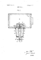
- FIG. 1 is a schematic view of a portion of an air-conditioning system illustrating the air terminal of the present invention in section; and I FIG. 2 is an enlarged sectional view-of the terminal of FIG. 1.
- a central air-conditioning apparatus including a filter 5, precooling coil 7, spray means 9, cooling coil 11, heating coil 13 and a fan 15, for heating, cooling, humidifying and filtering the air as desired, to provide conditioned air for passage to the area being conditioned.
- a supply air duct 17 is illustrativeof the plurality of ducts provided to supply conditioned air to ceiling air. terminals throughout the building.
- the ceiling terminal includes a primary chamber 19 lined with a sound-absorbing material 21 such as'glass-fiber blanket.
- the primary chamber' is ordinarily open at both ends for connecting a series of terminals end to end to provide a complete air discharge system. Suitable end pieces, not shown, are utilized to cap the end terminals in the series.
- An air supply distribution plate 23 having a plurality of collared opening 25 therein is provided to evenly distribute the supply air from primary chamber 19 into the distribution chamber 27 which is defined by the top and sidewalls of distribution plate 23.
- the air supplied to the distribution chamber from the primary chamber should have minimal nonvertical velocity components. Since the air supplied to the ceiling terminal is ordinarily introduced horizontally into the end or side of the terminal, there is a large horizontal velocity component to the air stream within the conduit section.
- the distribution plate employing a large number of collared openings is very effective in providing an efficient, nonturbulent vertical diversion of the air stream from primary chamber 19 into distribution chamber 27. This minimizes noise generation within the terminal.
- the collars divert the horizontal velocity component of the air stream so that the velocity components of the air stream within distribution chamber 27 are vertical. For an optimum air discharge pattern from the plate, the depth of the collar should approximate the diameter of the collared opening.
- each collar is constant throughout the entire circumference thereof to provide a discharge opening parallel to the plane of the distribution plate.
- the geometry of the opening itself may have a tendency to effect an attachment of the air stream to a portion of the wall forming the opening. This attachment can cause the stream therefrom is obtained which minimizes the tendency of the air stream to flow in a nonvertical direction within the dis tribution chamber.
- the bottom of distribution chamber 27 includes aligned cutoff plates 29 which are provided with a curved surface 30 for engagement by bladders 31 and 33 to form a damper.
- the curved surfaces smooth the flow of air through the damper to minimize the pressure drop therethrough when the bladder is fully deflated and provide a Iownoise level over the entire operating range of the terminal as bladder inflation is varied between a fully deflated position and a fully inflated position.
- the surface 30 is covered with felt 32 to further minimize noise.
- the area of the openings between the bladders and the cutoff plates can be varied. This feature can be utilized to provide avariety of modes of terminal operation. If it is desired to maintain a constant discharge of air from the terminal, a pressure responsive control may be employed to inflate the bladders in response to supply air pressure to reduce the area between the bladders and cutoff plates as duct pressure increases and to increase the area therebetween as duct pressure decreases. If it is desired to control the terminal to provide a constant room temperature under varying cooling loads, the bladder inflation may be controlled by a thermostat responsive to room temperature to provide an increased quantity of air flow from the terminal as the cooling load increases and a decreased-quantity of air flow from the terminal as cooling load decreases.
- the bladders 31 and 33 are adhesively'mounted on a central partition assembly comprised of opposed, generally convex plates 35 and diffuser triangle 37.
- the plates have a V-shaped recess therein so that the bladders are completely recessed within the plates when deflated. This provides a large area between the active walls 34 of the bladders and the cutoff plates for maximum air flow therebetween. Further, the recessed bladder provides a smooth surface along the plate 35 to minimize air turbulence.
- the walls 34 of the bladders are concave. When the bladders are fully deflated, the active walls of the bladders are out of the air stream to minimize the possibility of bladder flutter.
- the distance between the cutoff plate and wall 34 of the bladder is increased. This provides a greater opening between the bladder and the cutoff plate when the bladder is fully deflated for maximum air flow therebetween. Further, a large movement of wall 34 from a concave to a convex position may be obtained without stretching the bladder material.
- the damper mechanism is disposed a substantial distance upstream from the discharge openings in the terminal to provide sufficient space therebetween to absorb any noise generated by the damper mechanism.
- downwardly extending walls 39 which form air passages in conjunction with plates 35, are lines with a soundabsorbing material such as glass-fiber blankets 45.
- Outlet members 41 having outwardly flared lower portions 43 thereon are affixed, as by welding, to the walls 39.
- the convex plates prevent direct, straight-line passage of sound energy waves from the damper into the area being conditioned.
- the sound waves generated at the damper strike the sound absorbing blankets 45 where they are absorbed, to prevent passage of noise from the terminal.
- the upper portion of the passageway formed between the plate 35 and the wall 39 has a constantly decreasing cross-sectional area in the direction of air flow while the lower portion of the passageway has a constantly increasing cross-sectional area in the direction of air flow. This change in cross-sectional area of the passageway in conjunction with the sound-absorbing blankets 45 aids in the dissipation of sound energy which may be generated upstream of the passageway.
- the discharged air stream should attach and remain attached to the ceiling to a location remote from the terminal before dropping into the area being conditioned. This assures a supply of conditioned air to areas remote from the terminal. Another advantage is that room air will be induced by the discharged air stream and will mix therewith to temper the stream so that the air stream temperature is not disproportionate to the room temperature, thereby providing even temperatures throughout the area being conditioned.
- the ceiling terminal of the present invention is adapted for use in the center of an area being conditioned or for placement above a partition for air flow away from the partition in both directions. This creates a problem in that there is a tendency for the discharged air streams to attach to the partition rather than the ceiling. Since the terminal is adapted for discharging a variable quantity of air, there is also a tendency for the air stream to detach from the ceiling at low flow rates.
- a definite relationship between the radius R of the flared portions 43, the spacing b between the portions 43 and the diffuser triangle 37, and the angle aof the upper walls of the diffuser triangle must be maintained to assure that the discharged air stream attaches to the ceiling for proper distribution of air within the area being conditioned.
- the angle atherefore should be within a range of to 45 while the b/R ratio should be within the range of .10 to .7.
- the preferred embodiment illustrated has a radius R of one half inch, a distance b of 3/16 inch and an angle aof 20. This results in a b/R ratio of .375.
- the described ceiling air terminal is capable of efficiently discharging a large quantity of conditioned air at low noise levels with minimal temperature variations within the area being conditioned.
- An air terminal comprising:
- a primary chamber adapted for connection to a scarce of conditioned air
- a distribution plate disposed between said primary chamber and said distribution chamber, said distribution plate having a plurality of openings formed therein for passage of conditioned air from said primary chamber into said air distribution chamber.
- an inflatable bladder disposed within said recess, the outer surface of said bladder residing substantially flush with the surface of said downwardly projecting plate member when said bladder is deflated; and a cutoff plate disposed opposite said bladder for cooperation therewith to restrict flow of air therebetween when said bladder is inflated.
- An air terminal comprising: A
- a primary chamber adapted for connection to a source of conditioned air
- a distribution plate disposed between said primary chamber and said distribution chamber, said distribution plate having a plurality of openings formed therein for passage of conditioned air from said primary chamber into said air distribution chamber;
- a downwardly projecting plate member disposed opposite said wall member to form a space therebetween for passage of air therethrough from said distribution chamber, said plate member having a generally concave recess formed therein;
- an inflatable bladder having a generally V-shaped conflguration disposed within said recess, the outer surface of said bladder assuming a generally concave configuration when deflated;
- a cutoff plate disposed opposite said bladder for cooperation therewith to restrict flow of air therebetween when said bladder is inflated.
- An air terminal according to claim 1 further including:
- a second downwardly projecting convex plate member associated with said first downwardly projecting convex plate member to form a partition therewith between said sound-absorbing material on said wall members to form two spaces therebetween for passage of air therethrough from said distribution chamber, the upper portion of said passages having a decreasing cross-sectional area in the direction of air flow and the lower portion of said passages having an increasing cross-sectional area in the direction of air flow to dissipate sound energy within said passage, said second plate member having a generally concave recess formed therein:
- a second inflatable bladder disposed within the recess in said second downwardly projecting plate member, the outer surface of said second bladder residing substantially flush with the surface of second downwardly projecting plate member when said bladder is deflated;
- a second cutoff plate disposed opposite said second bladder for cooperation therewith to restrict flow of air therebetween when said bladder is inflated.
- An air terminal according to claim 2 further including:
- a second downwardly projecting plate member associated with said first downwardly projecting plate member to form a partition therewith between said wall members to form two spaces therebetween for passage of air therethrough from said distribution chamber, said second downwardly projecting plate member having a generally concave recess formed therein;
- a second inflatable bladder having a generally V-shaped configuration disposed within the recess of said second downwardly projecting plate member, the outer surface of said second bladder assuming a generally concave configuration when deflated; and v a second cutoff plate disposed opposite said second bladder for cooperation therewith to restrict flow of air therebetween when said bladder is inflated.
Abstract
A ceiling terminal to distribute conditioned air into an area to be conditioned employing a damper comprised of inflatable bladders to regulate the quantity of air discharged into the area served thereby.
Description
i United States Patent [72] Inventor Carl C. Herb [56] References Cited Syracuse, UNITED STATES PATENTS i 1 PP 7791833 1931.356 10/1933 Porter 189/63 22 Filed Nov. 29, 1968 2,895,505 7/1959 Bachus 251/5X 1 Jam 1971 3,082,676 3/1963 Church et al. 98/40 1 Ass'gnee Cmpmm" 3,383,999 5/1968 Fragnito et al.... 98/40 Syracuse 3,434,409 3/1969 Fragnito 236/49x a corporation of Delaware Primary ExaminerAlbert W. Dav1s, Jr. Attorneys-Harry G. Martin, Jr. and Herman Seid 54] CEILING AIR TERMINAL 4 Claims, 2 Drawing Figs.
[52] U.S. Cl 98/40,
98/4]; 137/601: l8I/50:25l/5 51 Int. Cl F24f 13/06, ABSTRACT= A ceiling terminal to distribute conditioned air 34f 13/ 10; 1: 1 7/17 into an area to be conditioned employing a damper comprised [50] Field of Search 98/40, B, D, of inflatable bladders t9 regulat the q y of air discharged into the area served thereby.
PATENTED JAN 12ml SHEU 1 OF 2 FIG. I
INVENTOR.
CARL C. HERB. BY
WSW
ATTORNEY.
PATENTEU JAN 1 21911 SHEET 2 [IF 2 FIG. 2
INVEN'I'( )R. CARL C. HERB.
ATTORNEY.
CEILING AIR TERMINAL BACKGROUND OF THE INVENTION bladder flutter and provide a throttling area variable over a wide range. I
SUMMARY or THE-INVENTION This invention relates to a ceiling air terminal employing two substantially V-shaped, inflatable bladders recessed in a center partition having convex walls. The V-shaped bladders permit a substantial variation in throttle area and do not project into the air stream under conditions of. maximum air flow through the unit to minimize noise generation. The convexshaped walls of the center partition prevent direct transmission of sound energy waves-from the damper to the discharge portion of the unit and provide a passage downstream from the bladder having an increasing cross-sectional area for dissipation of sound energy. i
BRIEF DESCRIPTION OF THE DRAWINGS FIG. 1 is a schematic view of a portion of an air-conditioning system illustrating the air terminal of the present invention in section; and I FIG. 2 is an enlarged sectional view-of the terminal of FIG. 1.
DESCRIPTION OF THE PREFERRED EMBODIMENT Referring more particularly to the drawing, there is illustrated a central air-conditioning apparatus including a filter 5, precooling coil 7, spray means 9, cooling coil 11, heating coil 13 and a fan 15, for heating, cooling, humidifying and filtering the air as desired, to provide conditioned air for passage to the area being conditioned.
A supply air duct 17 is illustrativeof the plurality of ducts provided to supply conditioned air to ceiling air. terminals throughout the building. The ceiling terminal includes a primary chamber 19 lined with a sound-absorbing material 21 such as'glass-fiber blanket. The primary chamber'is ordinarily open at both ends for connecting a series of terminals end to end to provide a complete air discharge system. Suitable end pieces, not shown, are utilized to cap the end terminals in the series. An air supply distribution plate 23 having a plurality of collared opening 25 therein is provided to evenly distribute the supply air from primary chamber 19 into the distribution chamber 27 which is defined by the top and sidewalls of distribution plate 23. To provide an optimum air discharge pattern, the air supplied to the distribution chamber from the primary chamber should have minimal nonvertical velocity components. Since the air supplied to the ceiling terminal is ordinarily introduced horizontally into the end or side of the terminal, there is a large horizontal velocity component to the air stream within the conduit section. The distribution plate employing a large number of collared openings is very effective in providing an efficient, nonturbulent vertical diversion of the air stream from primary chamber 19 into distribution chamber 27. This minimizes noise generation within the terminal. The collars divert the horizontal velocity component of the air stream so that the velocity components of the air stream within distribution chamber 27 are vertical. For an optimum air discharge pattern from the plate, the depth of the collar should approximate the diameter of the collared opening. The depth of each collar is constant throughout the entire circumference thereof to provide a discharge opening parallel to the plane of the distribution plate. In discharging air from an opening, the geometry of the opening itself may have a tendency to effect an attachment of the air stream to a portion of the wall forming the opening. This attachment can cause the stream therefrom is obtained which minimizes the tendency of the air stream to flow in a nonvertical direction within the dis tribution chamber.
The bottom of distribution chamber 27 includes aligned cutoff plates 29 which are provided with a curved surface 30 for engagement by bladders 31 and 33 to form a damper. The curved surfaces smooth the flow of air through the damper to minimize the pressure drop therethrough when the bladder is fully deflated and provide a Iownoise level over the entire operating range of the terminal as bladder inflation is varied between a fully deflated position and a fully inflated position. The surface 30 is covered with felt 32 to further minimize noise.
By varying the inflation of the bladders, the area of the openings between the bladders and the cutoff plates can be varied. This feature can be utilized to provide avariety of modes of terminal operation. If it is desired to maintain a constant discharge of air from the terminal, a pressure responsive control may be employed to inflate the bladders in response to supply air pressure to reduce the area between the bladders and cutoff plates as duct pressure increases and to increase the area therebetween as duct pressure decreases. If it is desired to control the terminal to provide a constant room temperature under varying cooling loads, the bladder inflation may be controlled by a thermostat responsive to room temperature to provide an increased quantity of air flow from the terminal as the cooling load increases and a decreased-quantity of air flow from the terminal as cooling load decreases.
The bladders 31 and 33 are adhesively'mounted on a central partition assembly comprised of opposed, generally convex plates 35 and diffuser triangle 37. The plates have a V-shaped recess therein so that the bladders are completely recessed within the plates when deflated. This provides a large area between the active walls 34 of the bladders and the cutoff plates for maximum air flow therebetween. Further, the recessed bladder provides a smooth surface along the plate 35 to minimize air turbulence.
By reference to the drawings, it can be seen that the walls 34 of the bladders are concave. When the bladders are fully deflated, the active walls of the bladders are out of the air stream to minimize the possibility of bladder flutter. By recessing the bladder within the plate 35 and providing the bladder with concave wall 34, the distance between the cutoff plate and wall 34 of the bladder is increased. This provides a greater opening between the bladder and the cutoff plate when the bladder is fully deflated for maximum air flow therebetween. Further, a large movement of wall 34 from a concave to a convex position may be obtained without stretching the bladder material.
The damper mechanism is disposed a substantial distance upstream from the discharge openings in the terminal to provide sufficient space therebetween to absorb any noise generated by the damper mechanism. For maximum sound absorption, downwardly extending walls 39 which form air passages in conjunction with plates 35, are lines with a soundabsorbing material such as glass-fiber blankets 45. Outlet members 41 having outwardly flared lower portions 43 thereon are affixed, as by welding, to the walls 39.
The convex plates prevent direct, straight-line passage of sound energy waves from the damper into the area being conditioned. The sound waves generated at the damper strike the sound absorbing blankets 45 where they are absorbed, to prevent passage of noise from the terminal. The upper portion of the passageway formed between the plate 35 and the wall 39 has a constantly decreasing cross-sectional area in the direction of air flow while the lower portion of the passageway has a constantly increasing cross-sectional area in the direction of air flow. This change in cross-sectional area of the passageway in conjunction with the sound-absorbing blankets 45 aids in the dissipation of sound energy which may be generated upstream of the passageway.
For proper air distribution within conditioned area, the discharged air stream should attach and remain attached to the ceiling to a location remote from the terminal before dropping into the area being conditioned. This assures a supply of conditioned air to areas remote from the terminal. Another advantage is that room air will be induced by the discharged air stream and will mix therewith to temper the stream so that the air stream temperature is not disproportionate to the room temperature, thereby providing even temperatures throughout the area being conditioned.
The ceiling terminal of the present invention is adapted for use in the center of an area being conditioned or for placement above a partition for air flow away from the partition in both directions. This creates a problem in that there is a tendency for the discharged air streams to attach to the partition rather than the ceiling. Since the terminal is adapted for discharging a variable quantity of air, there is also a tendency for the air stream to detach from the ceiling at low flow rates.
A definite relationship between the radius R of the flared portions 43, the spacing b between the portions 43 and the diffuser triangle 37, and the angle aof the upper walls of the diffuser triangle must be maintained to assure that the discharged air stream attaches to the ceiling for proper distribution of air within the area being conditioned. The angle atherefore should be within a range of to 45 while the b/R ratio should be within the range of .10 to .7.
For quiet operation of the unit, it is desirable to utilize a diffuser triangle having a large angle 0:. However, as angle aincreases, the range of the b/R ratio for stable air flow decreases. For example, with an angle aof 45 unstable air flow ordinarily is encountered if the b/R ratio exceeds .25 while an angle aof 0 while productive of excessive noise, will provide stable air flow as the b/R ratio ranges from .l O to .7
In order to provide a unit that is as unobtrusive as possible, and within acceptable noise lever levels, the preferred embodiment illustrated has a radius R of one half inch, a distance b of 3/16 inch and an angle aof 20. This results in a b/R ratio of .375.
The described ceiling air terminal is capable of efficiently discharging a large quantity of conditioned air at low noise levels with minimal temperature variations within the area being conditioned.
While I have described a preferred embodiment of my invention, it is to be understood that the invention is not limited thereto, but may be otherwise embodied within the scope of the following claims.
lclaim:
1; An air terminal comprising:
a primary chamber adapted for connection to a scarce of conditioned air;
an air distribution chamber associated with said primary chamber;
a distribution plate disposed between said primary chamber and said distribution chamber, said distribution plate having a plurality of openings formed therein for passage of conditioned air from said primary chamber into said air distribution chamber.
a downwardly projecting wall member associated with said distribution chamber;
a downwardly projecting convex plate member disposed opposite said wall member;
sound-absorbing material disposed on said downwardly projecting wall member opposite said downwardly projecting plate member so as to form a passage between said plate member and said sound-absorbing material, the upper portion of said passage having a decreasing cross-sectional area in the direction of air flow and the lower portion of said passage having an increasing cross-sectional area in the direction of air flow to dissipate sound energy within said passage, said plate member having a generally concave recess formed therein;
an inflatable bladder disposed within said recess, the outer surface of said bladder residing substantially flush with the surface of said downwardly projecting plate member when said bladder is deflated; and a cutoff plate disposed opposite said bladder for cooperation therewith to restrict flow of air therebetween when said bladder is inflated.
2. An air terminal comprising: A
a primary chamber adapted for connection to a source of conditioned air;
an air distribution chamber associated with said primary chamber;
a distribution plate disposed between said primary chamber and said distribution chamber, said distribution plate having a plurality of openings formed therein for passage of conditioned air from said primary chamber into said air distribution chamber;
a downwardly projecting wall member associated with said distribution chamber;
a downwardly projecting plate member disposed opposite said wall member to form a space therebetween for passage of air therethrough from said distribution chamber, said plate member having a generally concave recess formed therein;
an inflatable bladder having a generally V-shaped conflguration disposed within said recess, the outer surface of said bladder assuming a generally concave configuration when deflated; and
a cutoff plate disposed opposite said bladder for cooperation therewith to restrict flow of air therebetween when said bladder is inflated.
3. An air terminal according to claim 1 further including:
a second downwardly projecting wall member associated with said distribution chamber, said second downwardly projecting wall member having sound-absorbing material disposed thereon;
a second downwardly projecting convex plate member associated with said first downwardly projecting convex plate member to form a partition therewith between said sound-absorbing material on said wall members to form two spaces therebetween for passage of air therethrough from said distribution chamber, the upper portion of said passages having a decreasing cross-sectional area in the direction of air flow and the lower portion of said passages having an increasing cross-sectional area in the direction of air flow to dissipate sound energy within said passage, said second plate member having a generally concave recess formed therein:
a second inflatable bladder disposed within the recess in said second downwardly projecting plate member, the outer surface of said second bladder residing substantially flush with the surface of second downwardly projecting plate member when said bladder is deflated; and
a second cutoff plate disposed opposite said second bladder for cooperation therewith to restrict flow of air therebetween when said bladder is inflated.
4. An air terminal according to claim 2 further including:
a second downwardly projecting wall member associated with said distribution chamber;
a second downwardly projecting plate member associated with said first downwardly projecting plate member to form a partition therewith between said wall members to form two spaces therebetween for passage of air therethrough from said distribution chamber, said second downwardly projecting plate member having a generally concave recess formed therein;
a second inflatable bladder having a generally V-shaped configuration disposed within the recess of said second downwardly projecting plate member, the outer surface of said second bladder assuming a generally concave configuration when deflated; and v a second cutoff plate disposed opposite said second bladder for cooperation therewith to restrict flow of air therebetween when said bladder is inflated.
Claims (4)
1. An air terminal comprising: a primary chamber adapted for connection to a source of conditioned air; an air distribution chamber associated with said primary chamber; a distribution plate disposed between said primary chAmber and said distribution chamber, said distribution plate having a plurality of openings formed therein for passage of conditioned air from said primary chamber into said air distribution chamber. a downwardly projecting wall member associated with said distribution chamber; a downwardly projecting convex plate member disposed opposite said wall member; sound-absorbing material disposed on said downwardly projecting wall member opposite said downwardly projecting plate member so as to form a passage between said plate member and said soundabsorbing material, the upper portion of said passage having a decreasing cross-sectional area in the direction of air flow and the lower portion of said passage having an increasing cross-sectional area in the direction of air flow to dissipate sound energy within said passage, said plate member having a generally concave recess formed therein; an inflatable bladder disposed within said recess, the outer surface of said bladder residing substantially flush with the surface of said downwardly projecting plate member when said bladder is deflated; and a cutoff plate disposed opposite said bladder for cooperation therewith to restrict flow of air therebetween when said bladder is inflated.
2. An air terminal comprising: a primary chamber adapted for connection to a source of conditioned air; an air distribution chamber associated with said primary chamber; a distribution plate disposed between said primary chamber and said distribution chamber, said distribution plate having a plurality of openings formed therein for passage of conditioned air from said primary chamber into said air distribution chamber; a downwardly projecting wall member associated with said distribution chamber; a downwardly projecting plate member disposed opposite said wall member to form a space therebetween for passage of air therethrough from said distribution chamber, said plate member having a generally concave recess formed therein; an inflatable bladder having a generally V-shaped configuration disposed within said recess, the outer surface of said bladder assuming a generally concave configuration when deflated; and a cutoff plate disposed opposite said bladder for cooperation therewith to restrict flow of air therebetween when said bladder is inflated.
3. An air terminal according to claim 1 further including: a second downwardly projecting wall member associated with said distribution chamber, said second downwardly projecting wall member having sound-absorbing material disposed thereon; a second downwardly projecting convex plate member associated with said first downwardly projecting convex plate member to form a partition therewith between said sound-absorbing material on said wall members to form two spaces therebetween for passage of air therethrough from said distribution chamber, the upper portion of said passages having a decreasing cross-sectional area in the direction of air flow and the lower portion of said passages having an increasing cross-sectional area in the direction of air flow to dissipate sound energy within said passage, said second plate member having a generally concave recess formed therein: a second inflatable bladder disposed within the recess in said second downwardly projecting plate member, the outer surface of said second bladder residing substantially flush with the surface of second downwardly projecting plate member when said bladder is deflated; and a second cutoff plate disposed opposite said second bladder for cooperation therewith to restrict flow of air therebetween when said bladder is inflated.
4. An air terminal according to claim 2 further including: a second downwardly projecting wall member associated with said distribution chamber; a second downwardly projecting plate member associated with said first downwardly projecting plate member to form a partition therewith between said wall members to form two spaces theRebetween for passage of air therethrough from said distribution chamber, said second downwardly projecting plate member having a generally concave recess formed therein; a second inflatable bladder having a generally V-shaped configuration disposed within the recess of said second downwardly projecting plate member, the outer surface of said second bladder assuming a generally concave configuration when deflated; and a second cutoff plate disposed opposite said second bladder for cooperation therewith to restrict flow of air therebetween when said bladder is inflated.
Applications Claiming Priority (1)
| Application Number | Priority Date | Filing Date | Title |
|---|---|---|---|
| US77983368A | 1968-11-29 | 1968-11-29 |
Publications (1)
| Publication Number | Publication Date |
|---|---|
| US3554112A true US3554112A (en) | 1971-01-12 |
Family
ID=25117712
Family Applications (1)
| Application Number | Title | Priority Date | Filing Date |
|---|---|---|---|
| US3554112D Expired - Lifetime US3554112A (en) | 1968-11-29 | 1968-11-29 | Ceiling air terminal |
Country Status (6)
| Country | Link |
|---|---|
| US (1) | US3554112A (en) |
| DE (1) | DE1954347B2 (en) |
| FI (1) | FI53038C (en) |
| FR (1) | FR2024476A1 (en) |
| GB (1) | GB1281738A (en) |
| SE (1) | SE356356B (en) |
Cited By (12)
| Publication number | Priority date | Publication date | Assignee | Title |
|---|---|---|---|---|
| US4018160A (en) * | 1975-06-10 | 1977-04-19 | Carrier Corporation | Air conditioning terminal |
| US4182430A (en) * | 1978-09-20 | 1980-01-08 | Mitco Corporation | Branch take-off and silencer for an air distribution system |
| US4186876A (en) * | 1977-12-07 | 1980-02-05 | Carrier Corporation | System powered damper blade assembly for use in an air conditioning system |
| US4313522A (en) * | 1978-09-20 | 1982-02-02 | Mitco Corporation | Static pressure regain coupler for an air distribution system |
| US4324358A (en) * | 1980-07-02 | 1982-04-13 | Carrier Corporation | Minimum airflow control |
| US4352323A (en) * | 1978-08-18 | 1982-10-05 | Gulton Industries, Inc. | Air diffuser |
| US4432434A (en) * | 1982-01-07 | 1984-02-21 | Tempmaster Corporation | Sound absorbing arrangement for air handling units |
| US4499815A (en) * | 1980-08-06 | 1985-02-19 | Gulton Industries, Inc. | Air diffuser |
| US4851066A (en) * | 1983-12-19 | 1989-07-25 | Carrier Corporation | Snap-secured bladder for air-distribution terminal |
| US20070145158A1 (en) * | 2005-12-27 | 2007-06-28 | American Aldes Ventilation Corporation | Method and apparatus for passively controlling airflow |
| US9759442B2 (en) | 2005-12-27 | 2017-09-12 | American Aldes Ventilation Corporation | Method and apparatus for passively controlling airflow |
| US11482899B2 (en) * | 2018-12-14 | 2022-10-25 | Tdk Corporation | Rotating electrical machine with rotor having arc shaped permanent magnets |
Families Citing this family (1)
| Publication number | Priority date | Publication date | Assignee | Title |
|---|---|---|---|---|
| DE8708827U1 (en) * | 1987-06-25 | 1988-10-27 | Ltg Lufttechnische Gmbh, 7000 Stuttgart, De |
Citations (5)
| Publication number | Priority date | Publication date | Assignee | Title |
|---|---|---|---|---|
| US1931356A (en) * | 1932-09-20 | 1933-10-17 | Dewey E Porter | Gas engine temperature control |
| US2895505A (en) * | 1954-08-31 | 1959-07-21 | Western Electric Co | Pressure valve and control system for paper pulp machines |
| US3082676A (en) * | 1959-06-30 | 1963-03-26 | Carrier Corp | Air distributing unit |
| US3383999A (en) * | 1967-07-03 | 1968-05-21 | Carrier Corp | Ceiling air terminal |
| US3434409A (en) * | 1967-03-01 | 1969-03-25 | Carrier Corp | Air distribution unit |
-
1968
- 1968-11-29 US US3554112D patent/US3554112A/en not_active Expired - Lifetime
-
1969
- 1969-10-14 GB GB5049569A patent/GB1281738A/en not_active Expired
- 1969-10-28 FI FI309369A patent/FI53038C/fi active
- 1969-10-28 FR FR6936887A patent/FR2024476A1/fr active Pending
- 1969-10-29 DE DE19691954347 patent/DE1954347B2/en not_active Withdrawn
- 1969-11-26 SE SE1624469A patent/SE356356B/xx unknown
Patent Citations (5)
| Publication number | Priority date | Publication date | Assignee | Title |
|---|---|---|---|---|
| US1931356A (en) * | 1932-09-20 | 1933-10-17 | Dewey E Porter | Gas engine temperature control |
| US2895505A (en) * | 1954-08-31 | 1959-07-21 | Western Electric Co | Pressure valve and control system for paper pulp machines |
| US3082676A (en) * | 1959-06-30 | 1963-03-26 | Carrier Corp | Air distributing unit |
| US3434409A (en) * | 1967-03-01 | 1969-03-25 | Carrier Corp | Air distribution unit |
| US3383999A (en) * | 1967-07-03 | 1968-05-21 | Carrier Corp | Ceiling air terminal |
Cited By (16)
| Publication number | Priority date | Publication date | Assignee | Title |
|---|---|---|---|---|
| US4018160A (en) * | 1975-06-10 | 1977-04-19 | Carrier Corporation | Air conditioning terminal |
| US4186876A (en) * | 1977-12-07 | 1980-02-05 | Carrier Corporation | System powered damper blade assembly for use in an air conditioning system |
| US4352323A (en) * | 1978-08-18 | 1982-10-05 | Gulton Industries, Inc. | Air diffuser |
| US4182430A (en) * | 1978-09-20 | 1980-01-08 | Mitco Corporation | Branch take-off and silencer for an air distribution system |
| US4313522A (en) * | 1978-09-20 | 1982-02-02 | Mitco Corporation | Static pressure regain coupler for an air distribution system |
| US4324358A (en) * | 1980-07-02 | 1982-04-13 | Carrier Corporation | Minimum airflow control |
| US4499815A (en) * | 1980-08-06 | 1985-02-19 | Gulton Industries, Inc. | Air diffuser |
| US4432434A (en) * | 1982-01-07 | 1984-02-21 | Tempmaster Corporation | Sound absorbing arrangement for air handling units |
| US4851066A (en) * | 1983-12-19 | 1989-07-25 | Carrier Corporation | Snap-secured bladder for air-distribution terminal |
| US20070145158A1 (en) * | 2005-12-27 | 2007-06-28 | American Aldes Ventilation Corporation | Method and apparatus for passively controlling airflow |
| US7766734B2 (en) | 2005-12-27 | 2010-08-03 | American Aldes Ventilation Corporation | Method and apparatus for passively controlling airflow |
| US20100227541A1 (en) * | 2005-12-27 | 2010-09-09 | American Aldes Ventilation Corporation | Method and apparatus for passively controlling airflow |
| US9201428B2 (en) | 2005-12-27 | 2015-12-01 | American Aldes Ventilation Corporation | Method and apparatus for passively controlling airflow |
| US9759442B2 (en) | 2005-12-27 | 2017-09-12 | American Aldes Ventilation Corporation | Method and apparatus for passively controlling airflow |
| US10571140B2 (en) | 2005-12-27 | 2020-02-25 | American Aldes Ventilation Corporation | Method and apparatus for passively controlling airflow |
| US11482899B2 (en) * | 2018-12-14 | 2022-10-25 | Tdk Corporation | Rotating electrical machine with rotor having arc shaped permanent magnets |
Also Published As
| Publication number | Publication date |
|---|---|
| SE356356B (en) | 1973-05-21 |
| FI53038B (en) | 1977-09-30 |
| FR2024476A1 (en) | 1970-08-28 |
| DE1954347B2 (en) | 1971-09-16 |
| DE1954347A1 (en) | 1970-06-11 |
| FI53038C (en) | 1978-01-10 |
| GB1281738A (en) | 1972-07-12 |
Similar Documents
| Publication | Publication Date | Title |
|---|---|---|
| US3554112A (en) | Ceiling air terminal | |
| US2644389A (en) | Diffuser for air conditioning systems | |
| US3554111A (en) | Air conditioning terminal | |
| US2750865A (en) | Diffuser | |
| US2369119A (en) | Ventilating system | |
| US20060211365A1 (en) | Induction diffuser | |
| US3012760A (en) | Air conditioning units | |
| US4281592A (en) | Double induction unit | |
| US4142456A (en) | Air diffuser | |
| US3185069A (en) | Air distribution devices | |
| US7022010B1 (en) | Air conditioner with a circular air diffuser system | |
| US3059564A (en) | Low noise air distributor | |
| US4077310A (en) | Air conditioning terminal assembly | |
| US2269376A (en) | Diffuser for the outlets of air ducts | |
| US2821898A (en) | Air distribution outlet | |
| US2672087A (en) | Air distributing device | |
| US3677164A (en) | Ceiling air terminal | |
| US3084609A (en) | Air conditioning system | |
| US3703140A (en) | Ceiling air terminal | |
| US3177795A (en) | Airflow and noise controlling plenum diffuser assembly | |
| US2687746A (en) | High-pressure diffuser | |
| US3673946A (en) | Air diffuser | |
| US3818815A (en) | Smudge eliminating variable volume selective pattern control air diffuser | |
| US2432289A (en) | Ventilating system | |
| US3205809A (en) | Diffuser construction |