US347206A - Weather-strip - Google Patents
Weather-strip Download PDFInfo
- Publication number
- US347206A US347206A US347206DA US347206A US 347206 A US347206 A US 347206A US 347206D A US347206D A US 347206DA US 347206 A US347206 A US 347206A
- Authority
- US
- United States
- Prior art keywords
- strip
- door
- weather
- recess
- edges
- Prior art date
- Legal status (The legal status is an assumption and is not a legal conclusion. Google has not performed a legal analysis and makes no representation as to the accuracy of the status listed.)
- Expired - Lifetime
Links
Images
Classifications
-
- E—FIXED CONSTRUCTIONS
- E06—DOORS, WINDOWS, SHUTTERS, OR ROLLER BLINDS IN GENERAL; LADDERS
- E06B—FIXED OR MOVABLE CLOSURES FOR OPENINGS IN BUILDINGS, VEHICLES, FENCES OR LIKE ENCLOSURES IN GENERAL, e.g. DOORS, WINDOWS, BLINDS, GATES
- E06B7/00—Special arrangements or measures in connection with doors or windows
- E06B7/16—Sealing arrangements on wings or parts co-operating with the wings
- E06B7/18—Sealing arrangements on wings or parts co-operating with the wings by means of movable edgings, e.g. draught sealings additionally used for bolting, e.g. by spring force or with operating lever
- E06B7/20—Sealing arrangements on wings or parts co-operating with the wings by means of movable edgings, e.g. draught sealings additionally used for bolting, e.g. by spring force or with operating lever automatically withdrawn when the wing is opened, e.g. by means of magnetic attraction, a pin or an inclined surface, especially for sills
Definitions
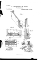
- FIG. 1 is a perspective view of the lower portion of a door-frame and door provided with our improved weather-strip, showing the door opened.
- Fig. 2 is front view of the same, showing parts broken away, and showing the door closed.
- Fig. 3 is a vertical sectional view on line at m, Fig. 2.
- Fig. 4 is a vertical sectional view on line y y, Fig. 3, and
- Fig. 5 is a perspective detail view of one of the hinges.
- Our invention has relation to that class of weather-strips for doors in which a strip is hinged near the lower edge of the door, and is tilted down, when the door is closed, by suitable mechanism; and it consists in theimp roved construction and combination of parts of such a weather-strip, as hereinafter more fully described and claimed.
- the letter A indicates the door.
- B is the sill, and O O are the jambs, of the door-frame.
- a molding or cleat,D is secured upon the outer side of the door, near the lower edge of the same, and is provided with elastic strips E E at its ends, which strips may bear against the jamhs of the door-frame when the door is closed.
- the under side of this molding or cleat is recessed longitudinally, as shown at F, and the hinged strip G fits with its rounded upper edge, H, in this recess and is hinged in it.
- the rounded edge of the strip is formed with recesses I, into which hingeears J project in pairs from the under side of the molding, the distance between the ears of each pair being less than the length of each recess in the upper edge of the strip.
- a pintle, K connects each pair of cars, and the outer edges of each pair of cars are connected by means of flanges L, having oblique downwardly-divergiug edges M, the out which forms the oblique edges extending nearly to the base-plate N of the cars, which plate is secured between the inner side of the molding and the front side of the door.
- Plates O are secured upon the under side of the hinged strip at the edges of the recesses in the edge of the same, and these plates are provided with perforated ears P 1?, which turn and slide upon the pintles of the ears secured to the molding, between which ears springs Q are wrapped around the pintles, bearingwith their projecting ends against the hinge-plates.
- the distance between each pair of cars projecting from the plate O is less than the distance between the ears projecting from the plate N, so that the former may slide upon the pint-1c between the latter, and the ears of the plate 0 are provided with outwardly-projecting lugs R It, which have inclined side edges, S, with which they may bear against the inclined edges M of the flanges upon the ears of the plate N.
- strip is formed at the end nearest to the hingeedge of the door with a longitudinal recess or bore, T,, within which fits a spiral spring, U, which bears against the inner end of the recess with its inner. end, while a screw-threaded bolt, V, fits in the outer end of the spring and is formed with a pointed outer end.
- this strip may be used in doors opening to either side, and that the molding or cleat will protect the hinges, and the spring-cushioned bolt and the recessed screw will serve to break or cushion the force with which the door is closed, preventing any injury to the parts forming the hinges. It will also be seen that by screwing the bolt and the screw farther out of their respective seats the strip will be forced farther to one side, and consequently be forced harder against the sill with its lower edge, while screwing the bolt and screws farther in will have the opposite effect.
Landscapes
- Engineering & Computer Science (AREA)
- Civil Engineering (AREA)
- Structural Engineering (AREA)
- Specific Sealing Or Ventilating Devices For Doors And Windows (AREA)
Description
6 s 00 w/ W 00 n 1 w I w. 0 A .l. u A d 9 u D m M & W
Hill,
WEATHER STRIP.
'G. G. SKINNER & G; M. BROOKS.
0 nAI 2 M 7 M 4 T 3 m m (No Model.)
jwmxm UNITED STATES PATENT Orrrcne GEORGE O. SKINNER AND CHARLES BROOKS, OF TROY, OHIO.
WEATHER-STRIP.
EPECIFICATION forming part of Letters Patent No. 347,206, dated August 10, 1886.
Application filed December 12, 1885. 'Serial No. 185,465. (No model.)
To all whom it may concern.-
Be it known that we, GEORGE O. SKINNEE and CHARLES M. BROOKS, both residents of Troy, in the county ofMiami and State of Ohio, have invented certain new and useful Improvements in Weather-Strips; and we doehereby declare that the following is a full, clear, and exact description of the invention, which will enable others skilledin the art to which it appertains to make and use the same, reference being had to the accompanying drawings, which form a part of this specification, and in which Figure 1 is a perspective view of the lower portion of a door-frame and door provided with our improved weather-strip, showing the door opened. Fig. 2 is front view of the same, showing parts broken away, and showing the door closed. Fig. 3 is a vertical sectional view on line at m, Fig. 2. Fig. 4 is a vertical sectional view on line y y, Fig. 3, and Fig. 5 is a perspective detail view of one of the hinges.
Similar letters of reference indicate corresponding parts in all the figures.
Our invention has relation to that class of weather-strips for doors in which a strip is hinged near the lower edge of the door, and is tilted down, when the door is closed, by suitable mechanism; and it consists in theimp roved construction and combination of parts of such a weather-strip, as hereinafter more fully described and claimed.
In the accompanying drawings, the letter A indicates the door. B is the sill, and O O are the jambs, of the door-frame. A molding or cleat,D, is secured upon the outer side of the door, near the lower edge of the same, and is provided with elastic strips E E at its ends, which strips may bear against the jamhs of the door-frame when the door is closed. The under side of this molding or cleat is recessed longitudinally, as shown at F, and the hinged strip G fits with its rounded upper edge, H, in this recess and is hinged in it. The rounded edge of the strip is formed with recesses I, into which hingeears J project in pairs from the under side of the molding, the distance between the ears of each pair being less than the length of each recess in the upper edge of the strip. A pintle, K, connects each pair of cars, and the outer edges of each pair of cars are connected by means of flanges L, having oblique downwardly-divergiug edges M, the out which forms the oblique edges extending nearly to the base-plate N of the cars, which plate is secured between the inner side of the molding and the front side of the door. Plates O are secured upon the under side of the hinged strip at the edges of the recesses in the edge of the same, and these plates are provided with perforated ears P 1?, which turn and slide upon the pintles of the ears secured to the molding, between which ears springs Q are wrapped around the pintles, bearingwith their projecting ends against the hinge-plates. The distance between each pair of cars projecting from the plate O is less than the distance between the ears projecting from the plate N, so that the former may slide upon the pint-1c between the latter, and the ears of the plate 0 are provided with outwardly-projecting lugs R It, which have inclined side edges, S, with which they may bear against the inclined edges M of the flanges upon the ears of the plate N. The
strip is formed at the end nearest to the hingeedge of the door with a longitudinal recess or bore, T,, within which fits a spiral spring, U, which bears against the inner end of the recess with its inner. end, while a screw-threaded bolt, V, fits in the outer end of the spring and is formed with a pointed outer end. A screw; WV, having a bore or recess, X, in its outer end or head, fits within a perforation in the jamb of the door, and serves as an abutment for the pointed bolt in the end of the strip when the door is closed, the point of the bolt bearing 'into the recess in the head of the screw. The
edges of the flanges, causing the strip to be turned downward at its free edge, bearing with thesaid edge against the sill of the doorframe. When the door is opened, the springs in the hinges will turn the strip up into the recess, and will at the same time force the inclined edges of the lugs and the flanges toward each other, causing the strip to slide toward the hinge-edge of the door. It will be seen that this strip may be used in doors opening to either side, and that the molding or cleat will protect the hinges, and the spring-cushioned bolt and the recessed screw will serve to break or cushion the force with which the door is closed, preventing any injury to the parts forming the hinges. It will also be seen that by screwing the bolt and the screw farther out of their respective seats the strip will be forced farther to one side, and consequently be forced harder against the sill with its lower edge, while screwing the bolt and screws farther in will have the opposite effect.
Having thus described our invention, .we claim and desire to secure by Letters Patent of the United States- 1. In aweather-strip, the combination, with the door, of a molding or cleat secured to the outside of the door, near the lower edge, and having a recess or groove in its under side and flexible strips at its ends, and a hinged strip having its roundedhinge-edge fitting into the recess orgroovc of the molding or cleat, as and for the purpose shown and set forth.
.pintles connecting the pairs ofears. and flanges connecting them formed with diverging oblique edges, plates secured to the under side of the strip, and having pairs of cars turning and sliding upon the pintles, and having ontwardly-projeeting lugs provided with oblique edges, and springs wrapped around the pi ntles between the ears of the strip and bearing with their ends against the two hinge-plates, as and for the purpose shown and set forth.
In testimony that we claim the toregoing as our own we have hereunto affixed our signatures in presence of two witnesses.
GEORGE SKINNER. CHARLES M. BROOKS.
\Vitnesses:
JOHN M. CAMPBELL, ARTHUR S. MCKINNEY.
Publications (1)
| Publication Number | Publication Date |
|---|---|
| US347206A true US347206A (en) | 1886-08-10 |
Family
ID=2416274
Family Applications (1)
| Application Number | Title | Priority Date | Filing Date |
|---|---|---|---|
| US347206D Expired - Lifetime US347206A (en) | Weather-strip |
Country Status (1)
| Country | Link |
|---|---|
| US (1) | US347206A (en) |
Cited By (1)
| Publication number | Priority date | Publication date | Assignee | Title |
|---|---|---|---|---|
| US2541421A (en) * | 1947-12-10 | 1951-02-13 | Charles R Hunter | Movable door closure and sealing means |
-
0
- US US347206D patent/US347206A/en not_active Expired - Lifetime
Cited By (1)
| Publication number | Priority date | Publication date | Assignee | Title |
|---|---|---|---|---|
| US2541421A (en) * | 1947-12-10 | 1951-02-13 | Charles R Hunter | Movable door closure and sealing means |
Similar Documents
| Publication | Publication Date | Title |
|---|---|---|
| US1091652A (en) | Folding gate. | |
| US347206A (en) | Weather-strip | |
| US746910A (en) | Weather-strip. | |
| US600984A (en) | Richard wilson | |
| US377838A (en) | Weather-strip | |
| US575224A (en) | Weather-strip for doors or windows | |
| US628735A (en) | Door-fastener. | |
| US103302A (en) | Improvement in weather-strips for doors | |
| US423343A (en) | Door-securer | |
| US237516A (en) | Jambs e | |
| US877593A (en) | Grain-car door. | |
| US787038A (en) | Door-fastening device for grain-doors. | |
| US335098A (en) | Augustus p | |
| US292120A (en) | Weather-strip | |
| US372084A (en) | Weather-strip for doors | |
| US407443A (en) | Weather-strip | |
| US391963A (en) | Weather-strip | |
| US525641A (en) | Weather-strip | |
| US205931A (en) | Improvement in door-checks | |
| US433460A (en) | Weather-strip | |
| US284602A (en) | Weather-strip | |
| US271957A (en) | Grain-door | |
| US484551A (en) | Door-jamb | |
| US361008A (en) | David habkeadee | |
| US813518A (en) | Weather-strip. |