US3441255A - Concrete mixer apparatus - Google Patents
Concrete mixer apparatus Download PDFInfo
- Publication number
- US3441255A US3441255A US672489A US3441255DA US3441255A US 3441255 A US3441255 A US 3441255A US 672489 A US672489 A US 672489A US 3441255D A US3441255D A US 3441255DA US 3441255 A US3441255 A US 3441255A
- Authority
- US
- United States
- Prior art keywords
- tractor
- trailer
- drum
- concrete
- hydraulic
- Prior art date
- Legal status (The legal status is an assumption and is not a legal conclusion. Google has not performed a legal analysis and makes no representation as to the accuracy of the status listed.)
- Expired - Lifetime
Links
- 239000000463 material Substances 0.000 description 15
- 239000012530 fluid Substances 0.000 description 10
- 241000196324 Embryophyta Species 0.000 description 9
- 230000007246 mechanism Effects 0.000 description 8
- 239000000203 mixture Substances 0.000 description 6
- 230000008878 coupling Effects 0.000 description 3
- 238000010168 coupling process Methods 0.000 description 3
- 238000005859 coupling reaction Methods 0.000 description 3
- 238000010276 construction Methods 0.000 description 2
- 230000009471 action Effects 0.000 description 1
- 239000004568 cement Substances 0.000 description 1
- 238000010586 diagram Methods 0.000 description 1
- ZZUFCTLCJUWOSV-UHFFFAOYSA-N furosemide Chemical compound C1=C(Cl)C(S(=O)(=O)N)=CC(C(O)=O)=C1NCC1=CC=CO1 ZZUFCTLCJUWOSV-UHFFFAOYSA-N 0.000 description 1
- -1 gravel Substances 0.000 description 1
- 208000008025 hordeolum Diseases 0.000 description 1
- 230000006872 improvement Effects 0.000 description 1
- 238000000034 method Methods 0.000 description 1
- 230000007935 neutral effect Effects 0.000 description 1
- 239000004576 sand Substances 0.000 description 1
- XLYOFNOQVPJJNP-UHFFFAOYSA-N water Substances O XLYOFNOQVPJJNP-UHFFFAOYSA-N 0.000 description 1
Images
Classifications
-
- B—PERFORMING OPERATIONS; TRANSPORTING
- B28—WORKING CEMENT, CLAY, OR STONE
- B28C—PREPARING CLAY; PRODUCING MIXTURES CONTAINING CLAY OR CEMENTITIOUS MATERIAL, e.g. PLASTER
- B28C5/00—Apparatus or methods for producing mixtures of cement with other substances, e.g. slurries, mortars, porous or fibrous compositions
- B28C5/42—Apparatus specially adapted for being mounted on vehicles with provision for mixing during transport
- B28C5/4296—Apparatus specially adapted for being mounted on vehicles with provision for mixing during transport mounted on a tractor or on a tractor wheel
Definitions
- CONCRETE MIXER APPARATUS Filed Oct. 5/1967 Sheet of 2 //Y vmm? United States Patent 3,441,255 CONCRETE MIXER APPARATUS Myron H. Ista, Phoenix, Ariz., assignor to .l. I. Case Company, Racine, Wis., a corporation of Wisconsin Filed Oct. 3, 1967, Ser. No. 672,489 Int. Cl. B28c /26 U.S. Cl. 259-146 ABSTRACT OF THE DISCLOSURE
- the hydraulic means includes a fluid pump on the tractor, a fluid motor on the carrier for rotatively driving the container and a control system connecting the pump and the motor.
- the carrier also has means for reversing direction of rotation of the container.
- the invention relates to industrial equipment in the concrete mixing field wherein concrete is transported from a mixing plant to a construction site.
- concrete carrying trucks are utilized to move the prepared concrete from a large mixing plant over great distances to the site.
- a batch plant is set up at the site to cut down on transport time and costs and to have readily available the required amounts of mixed concrete when ready for pour.
- the usual concrete mix trucks are needed to move the material to the pour area, where the material is then carted or pumped to the required location.
- the present invention relates to concrete conveying apparatus wherein a tractor normally used for loading materials is used for propelling and for driving a mixer container on a wheeled chassis.
- the tractor includes means for connecting and disconnecting the bucket lift arms to and from the concrete carrying vehicle.
- the loader 4 Claims 3,441,255 Patented Apr. 29, 1969 bucket is removed from the lift arms and the arms are attached to the vehicle for propelling and for guiding it.
- the vehicle which may be called a trailer or carrier, is supported on wheels and a barrel-shaped container or drum is carried thereon.
- the container includes mixing means and a delivery chute or spout for directing the concrete to the specific location at the pour site.
- the tractor and trailer combination also includes an engine driven hydraulic pump and control means for directing hydraulic fluid to a hydraulic motor on the trailer for rotating the material container in a forward or a reverse direction.
- the forward direction is taken here as meaning rotation for mixing and for keeping the material in a mixed condition as it is being transported from the batch plant to the pour area.
- the lift arm cylinders on the tractor are utilized for positioning the lift arms when connecting and disconnecting them from the trailer and they may also be used for raising and lowering the arms slightly when guiding or steering the trailer into place for loading or unloading the concrete.
- the hydraulic tilt or dump cylinders are not used for practic ing the invention, however the hydraulic control and circuitry normally used for tilting the loader bucket is applicable for driving the hydraulic motor on the trailer.
- FIGURE 1 is a side elevational view of a tractor loader with the loader bucket removed and the lift arms connected to a trailer;
- FIG. 2 is a plan view of the tractor-trailer apparatus
- FIG. 3 is a detailed view of the connection and drive between the tractor and trailer
- FIG. 4 is a view showing a tractor connected to a different type trailer.
- FIG. 5 is a schematic diagram of the hydraulic system.
- the tractor and concrete carrying trail-er provide a 'r'neans for utilizing equipments which would other-wise stand idle at certain times at the construction site.
- the barrel-shaped container or drum may be the usual apparatus except as modified for the present invention, and the tractor may be a regular wheeled loader type or it may be an articulated wheeled type again modified for this invention.
- a four-wheeled tractor 10 is connected to a four-wheeled trailer 12 carrying a concrete mixing drum 14,
- the tractor has a frame 16 on driving wheels 18 and 20 and steering wheels 22 and 24, and an engine 26 on the frame.
- the tractor may be a regular or an articulated type and the driving and steering wheels may be different sized or the driving and steering may be different from that shown. This would depend upon the type of idle equipment which is available at the site.
- a crawler type tractor may also be applicable in practicing the invention.
- the operators station 28 faces the end 30 of the tractor opposite from the engine 26.
- Lift arms 32 and 34 are attached at end 30 by means of pins 36 and 38 to the tractor frame and are adaptable to swing in an up and down direction about the pins.
- Hydraulically operated lift cylinders 40 and 42 are pivotally connected as at 44 and 46 to the frame and the cylinder rods 48 and 50 are connected to arms 32 and 34 at pins 52 and 54.
- the lift arms and the bucket are shown dotted in FIG. 1.
- the trailer 12 includes a frame 56 on rear wheels 58 and 60 and front wheels 62 and 64, the front wheels having steering mechanism such that they can be turned. Brackets 63 and 65 are secured to the front of trailer 12 for connection with lift arms 32 and 34 by means of pins 67 and 69.
- Trailer 12 carries the mixing drum 14 which is open at the rear end 66 and includes a hopper 68 for filling the drum with materials.
- the trailer also includes an operators station 70, controls 72 and a spout and chute for delivery of the mixed material from the drum.
- the drum of course, contains a conventional mixer adaptable for rotation with the drum in either a CW or a CCW direction. When viewed from end 66, rotation of the drum in a CW direction mixes the materials and rotation in a CCW direction empties the drum. Reversal of rotation of the drum is normally done at the pour site by operation of controls 72 at the material exit end.
- a hydraulic system shown schematically in FIG. 5, is provided for the apparatus, there being a supply of fluid 74 on the tractor, a pump 76 driven by the engine, control means 78 and fluid conduits connecting the pump, the controls and the lift cylinders.
- a control handle 81 is operated to move the lift cylinders
- At the front end 80 of drum 14 is drive mechanism 82 including gears for driving the drum in a forward or a reverse direction.
- a hydraulic motor 84 Connected to the drive mechanism is a hydraulic motor 84, the motor being connected to the control means 78 by fluid lines 86 and 88. Lines 86 and 88 have couplings 90 and 92 at the front of the operators station for connecting and disconnecting the lines. Similar couplings 94 and 96 are at the motor 84.
- the hydraulic circuit normally used for dumping the bucket is now used for driving the hydraulic motor for mixing the materials.
- the tractor operator moves a control handle 98 from a neutral to an open or drive position and the fluid flows through lines 86 and 88 and drives the hydraulic motor to turn the drum in a CW direction for mixing the materials.
- the loader bucket is unpinned from the lift arms 32 and 34 and the dump cylinders are disconnected from the bucket. These are shown structurally as 100 and 102 in FIG. 3 and dotted in FIG. 5.
- the dump links 104 and 106 are also disconnected from the bucket and may be allowed to hang on their pivots or they may be unpinned from links 108 and 110.
- the tractor is then driven to the trailer and the lift arms are raised by the lift cylinders to the position for connecting the arms to brackets 63 and 65 with pins 67 and 69.
- Fluid lines 86 and 88 are connected at couplings 90, 92, 94 and 96 and the apparatus is ready for operation.
- the tractor tows the trailer to the mix or batch plant and the proper amounts of sand, gravel, cement and water are deposited into the drum.
- the trailer is then towed to the pour site and the material is thoroughly mixed during transit by means of the pump driving the fluid through the motor for turning the drum.
- the speed of rotation of the motor may be varied such that for short distances the drum is turning at a higher speed whereas for longer distances the drum would be rotating slower to obtain proper mixing of the materials.
- the materials may be either partially or entirely mixed at the mixing plant so that rotation of the drum is required only to maintain the mixture during transport to the pour area.
- the apparatus gets to the pour site, the trailer is guided into place and an operator lowers the spout or chute and moves the controls 72 to reverse the direction of rotation of the drum.
- the hydraulic motor continues to be driven in the same direction by fluid flow from the pump on the tractor but the reversing gears on the drum drive mechanism turn the drum in a CCW direction to empty the contents.
- the reversing mechanism may be any suitable countershaft device 112 connected with a drive chain 114 for rotating the drum.
- FIG. 4 shows a wheeled tractor connected to a trailer having two wheels 116 and 118, wherein the lift arms are utilized to support a part of the load in addition to guiding the trailer.
- concrete is extremely heavy so the two-wheeled trailers would be used with smaller capacity drums.
- This apparatus is very similar to that described for four wheels except that a jack 120 may be used to support one end of the trailer when not connected to the tractor.
- the tractors shown may be of the standard rigid chassis type or they may be the articulated type which includes a pivot connection near the center of the tractor.
- the rigid chassis or the articulated type may be used with either the two or four-wheel trailer depending upon the availability and requirements of the particular equip ments.
- the articulated type shown presents a longitudinally rigid structure from the tractor center, at its point of articulation, through the trailer. So the trailer can be properly steered backwards.
- Another feature of the lift arms is to raise the front end of the trailer when it is nearly empty to speed up the operation and to remove all the concrete from the drum.
- the four wheel trailer offers advantages in that the drum outlet is at the rear and over the trailer rear wheels 58 and 60, as seen in FIGS. 1 and 21, and this permits maximum tipping of the trailer before its frame 56 or platform 70 meets the ground.
- a tractor including powered lift arms extending longitudinally of said tractor, a trailer including a rigid frame and ground-engaging wheels and a hitch for vertically pivotally connecting said tractor lift arms to said trailer to have the latter towed and lifted by said tractor, a concrete drum rotatably mounted on said trailer frame, powered rotation drive mechanism on said trailer frame and connected to said drum for rotating said drum, a power connection extending between said tractor and said powered rotation drive mechanism for driving the latter in the rotation of said drum, the improvement comprising said trailer hitch being rigid with said rigid frame for presenting a rigid structure to which said tractor lift arms are vertically pivotally connected on a horizontal axis, said tractor being of the articulate type which is pivotal about a vertical axis extending through a central portion of said tractor for providing the only and all ground steering and tracking action through the entire combined tractor and trailer.
- said trailer is provided with four said ground-engaging wheels with two thereof forwardly located and two thereof rearwardly located relative to a forward direction of said tractor, and said concrete drum includes an outlet disposed directly above said two rearwardly located wheels and with the remainder of said concrete drum being located toward said two forwardly located wheels, and said lift arms be ing movable relative to said tractor for raising said trailer off the ground about said two rearwardly located wheels for emptying said concrete drum.
- said tractor is of the loader bucket type and is convertible into powering said concrete drum and includes a hydraulic pump and first hydraulic means connected between said pump and said lift arms for powering said lift arms and thereby raise and lower said trailer, and said tractor includes second hydraulic means extending along said lift arms and being pivotally connected therewith and being of the type for pivoting a loader bucket mountable on said lift arms, tractor hydraulic hoses extending from said pump 5 to said second hydraulic means, and said powered rotation drive mechanism includes a hydraulic motor, and said power connection includes extension hydraulic hoses releasably coupled with said tractor hydraulic hoses for powering said hydraulic motor, and said tractor includes a hydraulic valve hydraulically connected with said pump for controlling hydraulic flow through said tractor hoses and said extension hoses to control said hydraulic motor.
Landscapes
- Engineering & Computer Science (AREA)
- Mechanical Engineering (AREA)
- Structural Engineering (AREA)
- Preparation Of Clay, And Manufacture Of Mixtures Containing Clay Or Cement (AREA)
Description
April 29, 1969 M. H. ISTA 3,441,255
CONCRETE MIXER APPARATUS Filed Oct. 5/1967 Sheet of 2 //Y vmm? United States Patent 3,441,255 CONCRETE MIXER APPARATUS Myron H. Ista, Phoenix, Ariz., assignor to .l. I. Case Company, Racine, Wis., a corporation of Wisconsin Filed Oct. 3, 1967, Ser. No. 672,489 Int. Cl. B28c /26 U.S. Cl. 259-146 ABSTRACT OF THE DISCLOSURE A concrete carrier propelled by a tractor having guide arms adaptable for quickly connecting and disconnecting the tractor from the carrier, and hydraulic means for rotating a container on the carrier. The hydraulic means includes a fluid pump on the tractor, a fluid motor on the carrier for rotatively driving the container and a control system connecting the pump and the motor. The carrier also has means for reversing direction of rotation of the container.
Background of the invention The invention relates to industrial equipment in the concrete mixing field wherein concrete is transported from a mixing plant to a construction site. As is well known, concrete carrying trucks are utilized to move the prepared concrete from a large mixing plant over great distances to the site. However, in the case of very large projects such as airfields, hydro dams, or high-ways, a batch plant is set up at the site to cut down on transport time and costs and to have readily available the required amounts of mixed concrete when ready for pour. At these batch plants, the usual concrete mix trucks are needed to move the material to the pour area, where the material is then carted or pumped to the required location. It is not uncommon for a contractor, on these large jobs, to have a dozen or more ready mix trucks available to haul the material from the batch plant to the pour area and, of course, there are times throughout the day when all of these trucks are in use at any one time as when the requirement for concrete is heavy, and there are other times when only a few are required depending upon the progress of the forming job.
Along with the concrete mix trucks there are usually other types of industrial equipment on the job such as bulldozers, graders, loaders, and the like which are used in preparing the site and also for backfill work. At certain times some of this equipment stands idle as when the forming is completed in a part of the project and the job is ready for pour, so that all available mix trucks are pressed into service. Between pours, many of these trucks stand idle so it has been a problem of the contractor to maintain as much equipment in use as possible at all times.
Because of the versatility of some of the machines, it is possible to utilize a machine for more than one function. In the case of concrete carrying vehicles it is seen that a tractor mounted loader, which may other-wise stand idle, can be adapted to propel the vehicle. The prior art shows the use of one truck or tractor being used for propelling two or more concrete carrying vehicles as taught in McNeil No. 3,282,448.
Summary of the invention The present invention relates to concrete conveying apparatus wherein a tractor normally used for loading materials is used for propelling and for driving a mixer container on a wheeled chassis. The tractor includes means for connecting and disconnecting the bucket lift arms to and from the concrete carrying vehicle. The loader 4 Claims 3,441,255 Patented Apr. 29, 1969 bucket is removed from the lift arms and the arms are attached to the vehicle for propelling and for guiding it. The vehicle, which may be called a trailer or carrier, is supported on wheels and a barrel-shaped container or drum is carried thereon. The container includes mixing means and a delivery chute or spout for directing the concrete to the specific location at the pour site.
The tractor and trailer combination also includes an engine driven hydraulic pump and control means for directing hydraulic fluid to a hydraulic motor on the trailer for rotating the material container in a forward or a reverse direction. The forward direction is taken here as meaning rotation for mixing and for keeping the material in a mixed condition as it is being transported from the batch plant to the pour area. The lift arm cylinders on the tractor are utilized for positioning the lift arms when connecting and disconnecting them from the trailer and they may also be used for raising and lowering the arms slightly when guiding or steering the trailer into place for loading or unloading the concrete. The hydraulic tilt or dump cylinders are not used for practic ing the invention, however the hydraulic control and circuitry normally used for tilting the loader bucket is applicable for driving the hydraulic motor on the trailer.
The advantages of the invention are apparent where it is desired to obtain maximum utility from tractor and trailer type equipments in the moving of concrete from the batch plant to the pour area. Each concrete carrying vehicle does not require its own propelling means, which, of course, greatly reduces the cost of these vehicles.
Other advantages of this apparatus will become apparent from a reading of the following description taken together with the annexed drawings, in which:
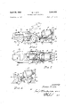
FIGURE 1 is a side elevational view of a tractor loader with the loader bucket removed and the lift arms connected to a trailer;
FIG. 2 is a plan view of the tractor-trailer apparatus;
FIG. 3 is a detailed view of the connection and drive between the tractor and trailer;
FIG. 4 is a view showing a tractor connected to a different type trailer; and
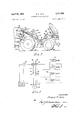
FIG. 5 is a schematic diagram of the hydraulic system.
The tractor and concrete carrying trail-er provide a 'r'neans for utilizing equipments which would other-wise stand idle at certain times at the construction site. The barrel-shaped container or drum may be the usual apparatus except as modified for the present invention, and the tractor may be a regular wheeled loader type or it may be an articulated wheeled type again modified for this invention.
As seen in FIGS. 1 and 2, a four-wheeled tractor 10 is connected to a four-wheeled trailer 12 carrying a concrete mixing drum 14, The tractor, of course, has a frame 16 on driving wheels 18 and 20 and steering wheels 22 and 24, and an engine 26 on the frame. As stated, the tractor may be a regular or an articulated type and the driving and steering wheels may be different sized or the driving and steering may be different from that shown. This would depend upon the type of idle equipment which is available at the site. A crawler type tractor may also be applicable in practicing the invention. The operators station 28 faces the end 30 of the tractor opposite from the engine 26. Lift arms 32 and 34 are attached at end 30 by means of pins 36 and 38 to the tractor frame and are adaptable to swing in an up and down direction about the pins. Hydraulically operated lift cylinders 40 and 42, more clearly seen in FIG. 3, are pivotally connected as at 44 and 46 to the frame and the cylinder rods 48 and 50 are connected to arms 32 and 34 at pins 52 and 54. The lift arms and the bucket are shown dotted in FIG. 1.
The trailer 12 includes a frame 56 on rear wheels 58 and 60 and front wheels 62 and 64, the front wheels having steering mechanism such that they can be turned. Brackets 63 and 65 are secured to the front of trailer 12 for connection with lift arms 32 and 34 by means of pins 67 and 69. Trailer 12 carries the mixing drum 14 which is open at the rear end 66 and includes a hopper 68 for filling the drum with materials.
The trailer also includes an operators station 70, controls 72 and a spout and chute for delivery of the mixed material from the drum. The drum, of course, contains a conventional mixer adaptable for rotation with the drum in either a CW or a CCW direction. When viewed from end 66, rotation of the drum in a CW direction mixes the materials and rotation in a CCW direction empties the drum. Reversal of rotation of the drum is normally done at the pour site by operation of controls 72 at the material exit end.
A hydraulic system, shown schematically in FIG. 5, is provided for the apparatus, there being a supply of fluid 74 on the tractor, a pump 76 driven by the engine, control means 78 and fluid conduits connecting the pump, the controls and the lift cylinders. A control handle 81 is operated to move the lift cylinders At the front end 80 of drum 14 is drive mechanism 82 including gears for driving the drum in a forward or a reverse direction. Connected to the drive mechanism is a hydraulic motor 84, the motor being connected to the control means 78 by fluid lines 86 and 88. Lines 86 and 88 have couplings 90 and 92 at the front of the operators station for connecting and disconnecting the lines. Similar couplings 94 and 96 are at the motor 84. Since the loader bucket has been removed from the tractor, the hydraulic circuit normally used for dumping the bucket is now used for driving the hydraulic motor for mixing the materials. The tractor operator moves a control handle 98 from a neutral to an open or drive position and the fluid flows through lines 86 and 88 and drives the hydraulic motor to turn the drum in a CW direction for mixing the materials.
When it is desired to practice the present invention, the loader bucket is unpinned from the lift arms 32 and 34 and the dump cylinders are disconnected from the bucket. These are shown structurally as 100 and 102 in FIG. 3 and dotted in FIG. 5. The dump links 104 and 106 are also disconnected from the bucket and may be allowed to hang on their pivots or they may be unpinned from links 108 and 110. The tractor is then driven to the trailer and the lift arms are raised by the lift cylinders to the position for connecting the arms to brackets 63 and 65 with pins 67 and 69. Fluid lines 86 and 88 are connected at couplings 90, 92, 94 and 96 and the apparatus is ready for operation.
In operation the tractor tows the trailer to the mix or batch plant and the proper amounts of sand, gravel, cement and water are deposited into the drum. The trailer is then towed to the pour site and the material is thoroughly mixed during transit by means of the pump driving the fluid through the motor for turning the drum. Depending upon the distance to be traveled, the speed of rotation of the motor may be varied such that for short distances the drum is turning at a higher speed whereas for longer distances the drum would be rotating slower to obtain proper mixing of the materials. In some cases, the materials may be either partially or entirely mixed at the mixing plant so that rotation of the drum is required only to maintain the mixture during transport to the pour area. When the apparatus gets to the pour site, the trailer is guided into place and an operator lowers the spout or chute and moves the controls 72 to reverse the direction of rotation of the drum. The hydraulic motor continues to be driven in the same direction by fluid flow from the pump on the tractor but the reversing gears on the drum drive mechanism turn the drum in a CCW direction to empty the contents. The reversing mechanism may be any suitable countershaft device 112 connected with a drive chain 114 for rotating the drum.
FIG. 4 shows a wheeled tractor connected to a trailer having two wheels 116 and 118, wherein the lift arms are utilized to support a part of the load in addition to guiding the trailer. As is well known, concrete is extremely heavy so the two-wheeled trailers would be used with smaller capacity drums. This apparatus is very similar to that described for four wheels except that a jack 120 may be used to support one end of the trailer when not connected to the tractor.
The tractors shown may be of the standard rigid chassis type or they may be the articulated type which includes a pivot connection near the center of the tractor. The rigid chassis or the articulated type may be used with either the two or four-wheel trailer depending upon the availability and requirements of the particular equip ments. However, the articulated type shown presents a longitudinally rigid structure from the tractor center, at its point of articulation, through the trailer. So the trailer can be properly steered backwards. Another feature of the lift arms is to raise the front end of the trailer when it is nearly empty to speed up the operation and to remove all the concrete from the drum. In this event, the four wheel trailer offers advantages in that the drum outlet is at the rear and over the trailer rear wheels 58 and 60, as seen in FIGS. 1 and 21, and this permits maximum tipping of the trailer before its frame 56 or platform 70 meets the ground.
It is thus seen that herein shown and described is a versatile concrete carrying apparatus which makes use of machinery which may otherwise stand idle at certain times. While several embodiments have been shown and described, variations may occur to those skilled in the art, and it is to be understood that all such variations are contemplated as being within the scope of the invention. The invention is not intended to be taken as limited by the embodiments disclosed, nor in fact, in any manner except as defined in the following claims.
What is claimed as new and desired to be secured by Letters Patent of the United States is:
- 1. In a concrete conveying and handling apparatus, a tractor including powered lift arms extending longitudinally of said tractor, a trailer including a rigid frame and ground-engaging wheels and a hitch for vertically pivotally connecting said tractor lift arms to said trailer to have the latter towed and lifted by said tractor, a concrete drum rotatably mounted on said trailer frame, powered rotation drive mechanism on said trailer frame and connected to said drum for rotating said drum, a power connection extending between said tractor and said powered rotation drive mechanism for driving the latter in the rotation of said drum, the improvement comprising said trailer hitch being rigid with said rigid frame for presenting a rigid structure to which said tractor lift arms are vertically pivotally connected on a horizontal axis, said tractor being of the articulate type which is pivotal about a vertical axis extending through a central portion of said tractor for providing the only and all ground steering and tracking action through the entire combined tractor and trailer.
2. The subject matter of claim 1, wherein said trailer is provided with four said ground-engaging wheels with two thereof forwardly located and two thereof rearwardly located relative to a forward direction of said tractor, and said concrete drum includes an outlet disposed directly above said two rearwardly located wheels and with the remainder of said concrete drum being located toward said two forwardly located wheels, and said lift arms be ing movable relative to said tractor for raising said trailer off the ground about said two rearwardly located wheels for emptying said concrete drum.
3. The subject matter of claim 1, wherein said tractor is of the loader bucket type and is convertible into powering said concrete drum and includes a hydraulic pump and first hydraulic means connected between said pump and said lift arms for powering said lift arms and thereby raise and lower said trailer, and said tractor includes second hydraulic means extending along said lift arms and being pivotally connected therewith and being of the type for pivoting a loader bucket mountable on said lift arms, tractor hydraulic hoses extending from said pump 5 to said second hydraulic means, and said powered rotation drive mechanism includes a hydraulic motor, and said power connection includes extension hydraulic hoses releasably coupled with said tractor hydraulic hoses for powering said hydraulic motor, and said tractor includes a hydraulic valve hydraulically connected with said pump for controlling hydraulic flow through said tractor hoses and said extension hoses to control said hydraulic motor.
4. A method of utilizing a tractor loader of the type having lift arms supporting a bucket which is connected to hydraulic means for tipping the bucket for loading and dumping, the steps of removing the bucket from the lift arms, draft-attaching the lift arms to a trailer having ground-engaging wheels and having a hydraulic power unit and a rotating concrete drum connected to the power unit, connecting the hydraulic means to the power unit for power-rotating the drum, and controlling rotation of the drum from a location on the trailer.
References Cited UNITED STATES PATENTS 2,482,976 9/ 1949 Harwood 259-177 2,706,623 4/1955 Styes 259161 2,968,915 1/1961 Feistel 259-177 3,160,398 12/1964 Green 259177 3,180,628 4/1965 Pullin 259-177 15 ROBERT w. JENKINS, Primary Examiner.
US. Cl. X.R.
Applications Claiming Priority (1)
| Application Number | Priority Date | Filing Date | Title |
|---|---|---|---|
| US67248967A | 1967-10-03 | 1967-10-03 |
Publications (1)
| Publication Number | Publication Date |
|---|---|
| US3441255A true US3441255A (en) | 1969-04-29 |
Family
ID=24698771
Family Applications (1)
| Application Number | Title | Priority Date | Filing Date |
|---|---|---|---|
| US672489A Expired - Lifetime US3441255A (en) | 1967-10-03 | 1967-10-03 | Concrete mixer apparatus |
Country Status (1)
| Country | Link |
|---|---|
| US (1) | US3441255A (en) |
Cited By (1)
| Publication number | Priority date | Publication date | Assignee | Title |
|---|---|---|---|---|
| US3682091A (en) * | 1970-03-16 | 1972-08-08 | French Oil Mill Machinery | Rendering cooker |
Citations (5)
| Publication number | Priority date | Publication date | Assignee | Title |
|---|---|---|---|---|
| US2482976A (en) * | 1946-12-03 | 1949-09-27 | Fredie H Harwood | Portable concrete mixer |
| US2706623A (en) * | 1952-06-11 | 1955-04-19 | Fred J Styes | Concrete mixing, carrying and pouring attachment for a tractor |
| US2968915A (en) * | 1957-11-26 | 1961-01-24 | Halliburton Oil Well Cementing | Hydraulic mechanism for concrete mixer |
| US3160398A (en) * | 1963-01-24 | 1964-12-08 | Stothert & Pitt Ltd | Concrete mixing apparatus |
| US3180628A (en) * | 1961-10-24 | 1965-04-27 | Winget Ltd | Agitator dump truck for concrete and other semi-liquid materials |
-
1967
- 1967-10-03 US US672489A patent/US3441255A/en not_active Expired - Lifetime
Patent Citations (5)
| Publication number | Priority date | Publication date | Assignee | Title |
|---|---|---|---|---|
| US2482976A (en) * | 1946-12-03 | 1949-09-27 | Fredie H Harwood | Portable concrete mixer |
| US2706623A (en) * | 1952-06-11 | 1955-04-19 | Fred J Styes | Concrete mixing, carrying and pouring attachment for a tractor |
| US2968915A (en) * | 1957-11-26 | 1961-01-24 | Halliburton Oil Well Cementing | Hydraulic mechanism for concrete mixer |
| US3180628A (en) * | 1961-10-24 | 1965-04-27 | Winget Ltd | Agitator dump truck for concrete and other semi-liquid materials |
| US3160398A (en) * | 1963-01-24 | 1964-12-08 | Stothert & Pitt Ltd | Concrete mixing apparatus |
Cited By (1)
| Publication number | Priority date | Publication date | Assignee | Title |
|---|---|---|---|---|
| US3682091A (en) * | 1970-03-16 | 1972-08-08 | French Oil Mill Machinery | Rendering cooker |
Similar Documents
| Publication | Publication Date | Title |
|---|---|---|
| US3391776A (en) | Combination elevating scraper and loader | |
| US2219533A (en) | Hauling unit | |
| JPH0197703A (en) | Method and apparatus for paving asphalt aggregate | |
| US2413096A (en) | Portable loading machine | |
| US3620458A (en) | Dual-purpose vehicle | |
| US3038704A (en) | Transit mixer | |
| US3367636A (en) | Cement transporting and placing machine | |
| US2572776A (en) | Subgrade and shouldering machine | |
| US2859949A (en) | Forward discharging transit concrete mixer | |
| US2413097A (en) | Portable loading machine | |
| US3317194A (en) | Concrete mixer | |
| DE8320352U1 (en) | Excavator device | |
| US7712233B2 (en) | Particulate material spreading apparatus | |
| US3441255A (en) | Concrete mixer apparatus | |
| US3635364A (en) | Mobile working machine | |
| US5261739A (en) | Multifunction construction machine | |
| US3881706A (en) | Trailer having concrete mixer thereon | |
| US1943398A (en) | Combined loading and transporting equipment | |
| US4379672A (en) | Combination handling and conveying apparatus | |
| US3743432A (en) | Automated paving machine | |
| US2447071A (en) | Concrete mixer | |
| US3092259A (en) | Detachable hoisting boom for powered vehicle | |
| CN213264696U (en) | A loader with a rotating upper hopper | |
| CN213111594U (en) | A bucket loader | |
| US2991890A (en) | Side boom attachment for tractors |