US3441243A - Mold for precast building materials - Google Patents
Mold for precast building materials Download PDFInfo
- Publication number
- US3441243A US3441243A US503769A US3441243DA US3441243A US 3441243 A US3441243 A US 3441243A US 503769 A US503769 A US 503769A US 3441243D A US3441243D A US 3441243DA US 3441243 A US3441243 A US 3441243A
- Authority
- US
- United States
- Prior art keywords
- wall
- mold
- walls
- chambers
- shell
- Prior art date
- Legal status (The legal status is an assumption and is not a legal conclusion. Google has not performed a legal analysis and makes no representation as to the accuracy of the status listed.)
- Expired - Lifetime
Links
- 239000004566 building material Substances 0.000 title description 4
- 239000004567 concrete Substances 0.000 description 11
- 238000010276 construction Methods 0.000 description 9
- 238000010438 heat treatment Methods 0.000 description 9
- 238000000465 moulding Methods 0.000 description 7
- 239000000463 material Substances 0.000 description 5
- 238000005192 partition Methods 0.000 description 5
- 239000002184 metal Substances 0.000 description 4
- 229910052751 metal Inorganic materials 0.000 description 4
- 239000002990 reinforced plastic Substances 0.000 description 4
- 239000007788 liquid Substances 0.000 description 3
- 239000003365 glass fiber Substances 0.000 description 2
- 239000011178 precast concrete Substances 0.000 description 2
- 239000011150 reinforced concrete Substances 0.000 description 2
- 239000011347 resin Substances 0.000 description 2
- 229920005989 resin Polymers 0.000 description 2
- 239000002023 wood Substances 0.000 description 2
- 230000000694 effects Effects 0.000 description 1
- 238000009413 insulation Methods 0.000 description 1
- 239000012212 insulator Substances 0.000 description 1
- JEIPFZHSYJVQDO-UHFFFAOYSA-N iron(III) oxide Inorganic materials O=[Fe]O[Fe]=O JEIPFZHSYJVQDO-UHFFFAOYSA-N 0.000 description 1
- 230000001788 irregular Effects 0.000 description 1
- 150000002739 metals Chemical class 0.000 description 1
- 230000002093 peripheral effect Effects 0.000 description 1
- 230000035939 shock Effects 0.000 description 1
- 239000007787 solid Substances 0.000 description 1
Images
Classifications
-
- B—PERFORMING OPERATIONS; TRANSPORTING
- B28—WORKING CEMENT, CLAY, OR STONE
- B28B—SHAPING CLAY OR OTHER CERAMIC COMPOSITIONS; SHAPING SLAG; SHAPING MIXTURES CONTAINING CEMENTITIOUS MATERIAL, e.g. PLASTER
- B28B7/00—Moulds; Cores; Mandrels
- B28B7/40—Moulds; Cores; Mandrels characterised by means for modifying the properties of the moulding material
- B28B7/42—Moulds; Cores; Mandrels characterised by means for modifying the properties of the moulding material for heating or cooling, e.g. steam jackets, by means of treating agents acting directly on the moulding material
Definitions
- a mold for forming concrete panels having a spaced apart outer and inner wall. The space between the walls is partitioned in order to effect distribution of the heat supplied for curing the concrete panel.
- the present invention relates to the molding of building materials and particularly to an apparatus for molding concrete wherein the curing thereof is accelerated by the application of heat.
- molds for concrete and such have been of metal, reinforced concrete or wood. Molds which are made of wood tend to warp; and in order to provide the required shock resistance, they must be heavily constructed. On the other hand, metal molds tend to rust and are otherwise too heavy to be sufliciently portable. Reinforced concrete molds must also be of relatively large construction and they tend to chip.
- the aim of the present invention is to provide an improved mold of light weight construction.
- a further aim is to provide an improved mold for accelerated curing by heating.
- the construction of the mold can be defined generally as comprising a shell having at least an inner wall and an exterior wall, the exterior wall being spaced apart from the inner wall in order to provide an air space therebetween, and heating means provided between said walls for heating the air space, whereby equal distribution of heat is provided for the curing of the material to be molded.
- the mold comprises an open-faced trough-shaped shell for receiving the material to be molded, a cover for enclosing said shell, said shell comprising an inner wall and an outer wall spaced apart to form an air space therebetween, said walls being made of reinforced plastic material, the outer wall being adapted to rest on a supporting surface, means between said walls for supporting said inner wall within said outer wall, means provided between said walls for dividing said space into chambers, and heating elements adapted to supply heat to said chambers.
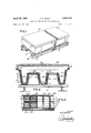
- FIGURE 1 is a perspective view of a mold construction in accordance with the present invention.
- FIGURE 2 is a vertical cross section taken along lines 22 of FIGURE 1; I
- FIGURE 3 is a view in cross section taken along line 3-3 of FIGURE 2;
- FIGURE 4 is an enlarged partial view showing a detail of FIGURE 3;
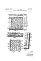
- FIGURE 5 is a cross sectional view taken along line 55 of FIGURE 4;
- FIGURE 6 is an enlarged partial view of a detail of FIGURE 2.
- FIGURE 7 is a view similar to FIGURE 4, but showing another embodiment of the construction in accordance with the invention.
- the mold 10 is shown comprising a lower shell 12 and a cover 14.
- the shell 12 is supported on a conventional base 16.
- the lower shell 12 may be made to any predetermined shape so as to suit architectural specifications. Normally, as shown in the embodiment in FIGURE 2, it is troughshaped and includes a floor 15 and side ledges 13 and comprises an inner wall 18 which is of a reinforced plastic material and preferably of resin bonded glass fiber construction. Spaced apart from the inner wall 18 is a similar outer wall 20 leaving a regular space therebetween. Wall 20 is supported directly on the base 16 and is supplemented by.a layer of insulation 21. The inner wall 18 is provided integrally with pairs of companion ribs 22a and 22b. When in an operative position, the wall 18 rests on the wall 20 by means of ribs 22a and 22b.
- the ribs 22a and 22b are provided in this case in a rectangular pattern as shown in FIGURE 4.
- the ribs 22a and 22b provide division walls in the open space between the walls 18 and 20 dividing into rectangular chambers 24.
- the chambers 24 are further subdivided into partitioned chambers 26 by means of a honeycomb Wall structure 28, having wall members 29 which extend the full height between walls 18 and 20.
- Heating elements which may be electrical elements or, as in this case, steam pipes 30, extend longitudinally in a spaced apart parallel relation between walls 18 and 20, through apertures 32 provided in the ribs 22a and 22b and apertures 34 provided in the honeycomb Wall members 29.
- the steam pipes 30 do not extend through all the partitioned chambers 26. Therefore, further apertures 36 are provided centrally of the chamber walls 29, communicating each chamber 26 with an adjacent chamber 26. As the air in a partitioned chamber 26 is heated by contact with the pipe 30 which extends through it, the air moves by convection to an adjacent chamber 26 until hot air is equally distributed in all the chambers 26.
- the partitioned chambers 26 may be of different shape such as shown in FIGURE 7.
- the cover 14 comprises a rectangular web portion 38 having peripheral downwardly extending flanges 40.
- the cover 14 can also be resin bonded glass fibre material and have the same structure as the shell 12.
- a series of steam pipes 30 are suspended longitudinally on the interior of the web portion 38 in a spaced apart parallel relation.
- Conventional clamp members or other devices are provided on the flanges 40 for securing the cover 14 to the side ledges 13.
- Ribs 122 form a rectangular chamber 124, but chamber 124 is further subdivided into cylindrical partitioned chamber 126. Steam pipes extend through only certain chambers 126, but the other chambers 126 communicate with each other by means of apertures 136.
- liquid concrete 11 is poured into the lower shell 12 and the cover 14 is clamped to the ledges 13.
- Steam from a steam source is forced through the steam pipes 30 both in the shell 12 and the cover 14.
- the heat is distributed to all the individual communicating partition chambers 26 by convection. Obviously the heat is easily transmitted through the thin wall 18 to the liquid concrete 11 in order to cure it.
- the mold is light-weight, economical and provides regular heat distribution with relatively minimum loss throughout to the concrete to be cured.
- a mold for molding precast concrete comprising an open-faced shell, a cover adapted for closing said shell, said shell and cover having similar constructions including a relatively thin inner wall and a relatively thin outer wall having a shape similar to said inner wall, but spaced apart therefrom, said inner wall including a plurality of integral intersecting ribs forming intersecting channels and extending between the walls to support the inner wall in spaced relation from said outer wall, a honeycomb wall structure arranged between the ribs and extending between said inner and outer walls forming cells with the honeycomb walls extending normal between the inner and outer walls, heating elements extending through some of the so-formed cells, said honeycomb walls defining apertures for allowing the air in the heated cells to communicate with the air in the unheated cells.
- a mold for molding precast concrete comprising an open-faced trough-shaped shell, a cover adapted for closing said shell, said shell including a relatively thin inner wall and a relatively thin outer wall having a shape similar to said inner wall, but spaced apart therefrom and defining an air space, a honeycomb wall structure arranged between said inner and outer walls forming air filled cells with the honeycomb walls extending fully and normal between the inner and outer walls, heating elements extending through some of the so-formed cells, said honeycomb walls defining apertures for allowing the air in the heated cells to communicate with the air in the unheated cells.
- a mold for molding concrete building panels comprising an open-faced shell formed to the contours of the proposed panel the shell including an inner wall forming the side surfaces and the bottom surfaces of the mold, an outer wall enveloping the inner Wall at a constant spacing therefrom and defining an air space therebetween, a plurality of ribs integral with one of the walls forming intersecting channels the ribs supporting the inner wall within the enveloping outer wall, the ribs defining closed air chambers with the inner and outer walls, intersecting partitions extending within the chambers formed by the ribs and forming sub-chambers with the inner and outer walls, heating elements extending within each chamber, the partitions defining apertures whereby the air heated by the elements is communicated to all the sub-chambers within the rib-defined chambers.
- a mold for molding building forms as defined in claim 4 wherein said partitions between said walls for dividing said space into chambers comprises verticallydisposed walls forming cylindrical chambers of a honeycomb pattern.
Landscapes
- Engineering & Computer Science (AREA)
- Manufacturing & Machinery (AREA)
- Chemical & Material Sciences (AREA)
- Ceramic Engineering (AREA)
- Mechanical Engineering (AREA)
- Laminated Bodies (AREA)
Description
April 29, 1969 P. o. WALZ 3,441,243
MOLD FOR PRECAST BUILDING MATERIALS Filed Oct. 23, 1965 Sheet of 2 INVENTOR Peter 0. WALZ A TTORNEYZ April 29, 1969 P. o. WALZ MOLD FOR PRECAST BUILDING MATERIALS Sheet Filed 001;. 25, 1965 FIG-.5
I'll/I 24 JNVENTOR Peter O. WALZ FIG.7
ATTORNEY United States Patent U.S. 'Cl. 249-81 7 Claims ABSTRACT OF THE DISCLOSURE A mold for forming concrete panels having a spaced apart outer and inner wall. The space between the walls is partitioned in order to effect distribution of the heat supplied for curing the concrete panel.
The present invention relates to the molding of building materials and particularly to an apparatus for molding concrete wherein the curing thereof is accelerated by the application of heat.
Heretofore, molds for concrete and such have been of metal, reinforced concrete or wood. Molds which are made of wood tend to warp; and in order to provide the required shock resistance, they must be heavily constructed. On the other hand, metal molds tend to rust and are otherwise too heavy to be sufliciently portable. Reinforced concrete molds must also be of relatively large construction and they tend to chip.
It has been, furthermore, proposed to include heating elements in the molds for accelerated curing thereof, but these elements were usually embedded in the solid form. Since the molds, such as concrete molds for instance, act as an insulator and much heat is prevented from reaching the liquid concrete. On the other hand, when metal molds are used, the relatively high conductivity of most practical metals allows the mold to be overheated in localized areas, thus presenting an irregular heat pattern.
The aim of the present invention is to provide an improved mold of light weight construction. A further aim is to provide an improved mold for accelerated curing by heating.
The construction of the mold can be defined generally as comprising a shell having at least an inner wall and an exterior wall, the exterior wall being spaced apart from the inner wall in order to provide an air space therebetween, and heating means provided between said walls for heating the air space, whereby equal distribution of heat is provided for the curing of the material to be molded.
In a preferred construction of the mold, it comprises an open-faced trough-shaped shell for receiving the material to be molded, a cover for enclosing said shell, said shell comprising an inner wall and an outer wall spaced apart to form an air space therebetween, said walls being made of reinforced plastic material, the outer wall being adapted to rest on a supporting surface, means between said walls for supporting said inner wall within said outer wall, means provided between said walls for dividing said space into chambers, and heating elements adapted to supply heat to said chambers.
Having thus generally described the nature of the invention, particular reference will be made to the accompanying drawings, showing by way of illustration preferred embodiments thereof and in which:
FIGURE 1 is a perspective view of a mold construction in accordance with the present invention;
FIGURE 2 is a vertical cross section taken along lines 22 of FIGURE 1; I
FIGURE 3 is a view in cross section taken along line 3-3 of FIGURE 2;
"ice
FIGURE 4 is an enlarged partial view showing a detail of FIGURE 3;
FIGURE 5 is a cross sectional view taken along line 55 of FIGURE 4;
FIGURE 6 is an enlarged partial view of a detail of FIGURE 2; and
FIGURE 7 is a view similar to FIGURE 4, but showing another embodiment of the construction in accordance with the invention.
Referring now in detail to the drawings and particularly to FIGURE 1, the mold 10 is shown comprising a lower shell 12 and a cover 14. The shell 12 is supported on a conventional base 16.
The lower shell 12 may be made to any predetermined shape so as to suit architectural specifications. Normally, as shown in the embodiment in FIGURE 2, it is troughshaped and includes a floor 15 and side ledges 13 and comprises an inner wall 18 which is of a reinforced plastic material and preferably of resin bonded glass fiber construction. Spaced apart from the inner wall 18 is a similar outer wall 20 leaving a regular space therebetween. Wall 20 is supported directly on the base 16 and is supplemented by.a layer of insulation 21. The inner wall 18 is provided integrally with pairs of companion ribs 22a and 22b. When in an operative position, the wall 18 rests on the wall 20 by means of ribs 22a and 22b.
The ribs 22a and 22b are provided in this case in a rectangular pattern as shown in FIGURE 4. The ribs 22a and 22b provide division walls in the open space between the walls 18 and 20 dividing into rectangular chambers 24. The chambers 24 are further subdivided into partitioned chambers 26 by means of a honeycomb Wall structure 28, having wall members 29 which extend the full height between walls 18 and 20.
Heating elements, which may be electrical elements or, as in this case, steam pipes 30, extend longitudinally in a spaced apart parallel relation between walls 18 and 20, through apertures 32 provided in the ribs 22a and 22b and apertures 34 provided in the honeycomb Wall members 29. However, the steam pipes 30 do not extend through all the partitioned chambers 26. Therefore, further apertures 36 are provided centrally of the chamber walls 29, communicating each chamber 26 with an adjacent chamber 26. As the air in a partitioned chamber 26 is heated by contact with the pipe 30 which extends through it, the air moves by convection to an adjacent chamber 26 until hot air is equally distributed in all the chambers 26.
The partitioned chambers 26 may be of different shape such as shown in FIGURE 7. In this embodiment the reference numerals corresponding to similar parts in the hereinbefore described embodiment have been raised by The cover 14 comprises a rectangular web portion 38 having peripheral downwardly extending flanges 40. The cover 14 can also be resin bonded glass fibre material and have the same structure as the shell 12. A series of steam pipes 30 are suspended longitudinally on the interior of the web portion 38 in a spaced apart parallel relation. Conventional clamp members or other devices are provided on the flanges 40 for securing the cover 14 to the side ledges 13.
It should be understood that more than one layer may be employed to form walls 18 and 20 and that more than one structural combination of Walls 18, 20 and wall structure 28 may be employed without departing from the scopeof the invention.
In operation, liquid concrete 11 is poured into the lower shell 12 and the cover 14 is clamped to the ledges 13. Steam from a steam source is forced through the steam pipes 30 both in the shell 12 and the cover 14.
As previously explained, the heat is distributed to all the individual communicating partition chambers 26 by convection. Obviously the heat is easily transmitted through the thin wall 18 to the liquid concrete 11 in order to cure it.
The advantages of such a construction is that the mold is light-weight, economical and provides regular heat distribution with relatively minimum loss throughout to the concrete to be cured.
I claim:
1. A mold for molding precast concrete, comprising an open-faced shell, a cover adapted for closing said shell, said shell and cover having similar constructions including a relatively thin inner wall and a relatively thin outer wall having a shape similar to said inner wall, but spaced apart therefrom, said inner wall including a plurality of integral intersecting ribs forming intersecting channels and extending between the walls to support the inner wall in spaced relation from said outer wall, a honeycomb wall structure arranged between the ribs and extending between said inner and outer walls forming cells with the honeycomb walls extending normal between the inner and outer walls, heating elements extending through some of the so-formed cells, said honeycomb walls defining apertures for allowing the air in the heated cells to communicate with the air in the unheated cells.
2. A mold for molding precast concrete, comprising an open-faced trough-shaped shell, a cover adapted for closing said shell, said shell including a relatively thin inner wall and a relatively thin outer wall having a shape similar to said inner wall, but spaced apart therefrom and defining an air space, a honeycomb wall structure arranged between said inner and outer walls forming air filled cells with the honeycomb walls extending fully and normal between the inner and outer walls, heating elements extending through some of the so-formed cells, said honeycomb walls defining apertures for allowing the air in the heated cells to communicate with the air in the unheated cells.
3. A mold as defined in claim 2, wherein said inner and outer walls are made from reinforced plastic.
4. A mold for molding concrete building panels, comprising an open-faced shell formed to the contours of the proposed panel the shell including an inner wall forming the side surfaces and the bottom surfaces of the mold, an outer wall enveloping the inner Wall at a constant spacing therefrom and defining an air space therebetween, a plurality of ribs integral with one of the walls forming intersecting channels the ribs supporting the inner wall within the enveloping outer wall, the ribs defining closed air chambers with the inner and outer walls, intersecting partitions extending within the chambers formed by the ribs and forming sub-chambers with the inner and outer walls, heating elements extending within each chamber, the partitions defining apertures whereby the air heated by the elements is communicated to all the sub-chambers within the rib-defined chambers.
5. A mold as defined in claim 4, wherein said shell is made from molded reinforced plastic.
6. A mold for molding concrete building forms as defined in claim 4 wherein the intersecting partitions provided between the walls include deformed chambers of diamond-shaped configuration.
7. A mold for molding building forms, as defined in claim 4 wherein said partitions between said walls for dividing said space into chambers comprises verticallydisposed walls forming cylindrical chambers of a honeycomb pattern.
References Cited UNITED STATES PATENTS 2,428,660 10/1947 Falk et a1. 249-79 3,018,087 1/1962 Steele l-56 XR 3,124,627 3/1964 Hood 24979 XR J. SPENCER OVERHOLSER, Primary Examiner.
Applications Claiming Priority (1)
| Application Number | Priority Date | Filing Date | Title |
|---|---|---|---|
| US50376965A | 1965-10-23 | 1965-10-23 |
Publications (1)
| Publication Number | Publication Date |
|---|---|
| US3441243A true US3441243A (en) | 1969-04-29 |
Family
ID=24003435
Family Applications (1)
| Application Number | Title | Priority Date | Filing Date |
|---|---|---|---|
| US503769A Expired - Lifetime US3441243A (en) | 1965-10-23 | 1965-10-23 | Mold for precast building materials |
Country Status (1)
| Country | Link |
|---|---|
| US (1) | US3441243A (en) |
Cited By (4)
| Publication number | Priority date | Publication date | Assignee | Title |
|---|---|---|---|---|
| US3822855A (en) * | 1971-03-15 | 1974-07-09 | Schmidt T As | Casting mold with steam-heated water jacket |
| US3922135A (en) * | 1970-09-28 | 1975-11-25 | Hans Haller | Mold for concrete C-profiles including a removeable core |
| US5110084A (en) * | 1988-06-10 | 1992-05-05 | Nissei Plan, Inc. | Form device for cellular concrete and method of making such concrete |
| US6086349A (en) * | 1992-05-26 | 2000-07-11 | Del Monte; Ernest J. | Variable wall concrete molding machine |
Citations (3)
| Publication number | Priority date | Publication date | Assignee | Title |
|---|---|---|---|---|
| US2428660A (en) * | 1945-03-24 | 1947-10-07 | American Brass Co | Water-cooled slab mold |
| US3018087A (en) * | 1958-04-11 | 1962-01-23 | Hexcel Products Inc | Heat transfer panel |
| US3124627A (en) * | 1963-03-18 | 1964-03-10 | Slotted |
-
1965
- 1965-10-23 US US503769A patent/US3441243A/en not_active Expired - Lifetime
Patent Citations (3)
| Publication number | Priority date | Publication date | Assignee | Title |
|---|---|---|---|---|
| US2428660A (en) * | 1945-03-24 | 1947-10-07 | American Brass Co | Water-cooled slab mold |
| US3018087A (en) * | 1958-04-11 | 1962-01-23 | Hexcel Products Inc | Heat transfer panel |
| US3124627A (en) * | 1963-03-18 | 1964-03-10 | Slotted |
Cited By (5)
| Publication number | Priority date | Publication date | Assignee | Title |
|---|---|---|---|---|
| US3922135A (en) * | 1970-09-28 | 1975-11-25 | Hans Haller | Mold for concrete C-profiles including a removeable core |
| US3822855A (en) * | 1971-03-15 | 1974-07-09 | Schmidt T As | Casting mold with steam-heated water jacket |
| US5110084A (en) * | 1988-06-10 | 1992-05-05 | Nissei Plan, Inc. | Form device for cellular concrete and method of making such concrete |
| US6086349A (en) * | 1992-05-26 | 2000-07-11 | Del Monte; Ernest J. | Variable wall concrete molding machine |
| US6086350A (en) * | 1992-05-26 | 2000-07-11 | Del Monte; Ernest J. | Variable wall concrete molding machine |
Similar Documents
| Publication | Publication Date | Title |
|---|---|---|
| US6649110B1 (en) | Method for manufacturing molded panels | |
| US3960999A (en) | Method of producing reinforced foamed structures | |
| GB2214947A (en) | Flexible form foil for floors | |
| US3441243A (en) | Mold for precast building materials | |
| GB2109026A (en) | Storage heater and bricks therefor | |
| US3081488A (en) | Mold form for fabricating modules | |
| US3737266A (en) | Mold for preparing a shaped article made of foamed thermoplastic resin | |
| ES2752099T3 (en) | Carrier element for a tunnel kiln trolley or wagon, tunnel kiln trolley or wagon with such carrier elements, as well as a tunnel kiln with such a tunnel kiln trolley or wagon | |
| US2994112A (en) | Acoustical insulation paneling system | |
| US4250670A (en) | Method and article for use in building construction | |
| US4188760A (en) | Masonry building block and method for forming such a block | |
| KR100705415B1 (en) | Heating structure using insulation panel and construction method | |
| US3170060A (en) | High stability test oven | |
| US4486888A (en) | Furnace, especially a ceramic or heating furnace | |
| KR102584805B1 (en) | Floor heating system having modularized floor pannels made of tempered glass for floor heating | |
| US1802085A (en) | Casing for water heaters | |
| JPS5988567A (en) | Heat insulating mold frame with electric heater | |
| US1750355A (en) | Construction of furnace or oven arches | |
| KR20210158058A (en) | Prefabricated red clay-hot water panel flooring | |
| GB1173319A (en) | Apparatus and process for the production of concrete pre-cast units | |
| KR950000190Y1 (en) | Prefab Ondol Plate | |
| KR900008668Y1 (en) | Panel for under floor heating | |
| US3595729A (en) | Pallet wherein spacer members are formed of rigid foam polymeric material | |
| CN216745222U (en) | Chinese-medicinal material drying device | |
| SU894124A1 (en) | Three-layer roof panel |